EP1990191A2 - Presse d'impression rotative pour bandes - Google Patents
Presse d'impression rotative pour bandes Download PDFInfo
- Publication number
- EP1990191A2 EP1990191A2 EP08008639A EP08008639A EP1990191A2 EP 1990191 A2 EP1990191 A2 EP 1990191A2 EP 08008639 A EP08008639 A EP 08008639A EP 08008639 A EP08008639 A EP 08008639A EP 1990191 A2 EP1990191 A2 EP 1990191A2
- Authority
- EP
- European Patent Office
- Prior art keywords
- cylinder
- web
- printing
- transfer cylinder
- rubber
- Prior art date
- Legal status (The legal status is an assumption and is not a legal conclusion. Google has not performed a legal analysis and makes no representation as to the accuracy of the status listed.)
- Withdrawn
Links
- 238000007639 printing Methods 0.000 title claims abstract description 88
- 230000005540 biological transmission Effects 0.000 claims abstract description 32
- 238000000034 method Methods 0.000 claims description 8
- 238000004519 manufacturing process Methods 0.000 claims description 6
- 108091006146 Channels Proteins 0.000 description 6
- PXHVJJICTQNCMI-UHFFFAOYSA-N Nickel Chemical compound [Ni] PXHVJJICTQNCMI-UHFFFAOYSA-N 0.000 description 2
- 238000005516 engineering process Methods 0.000 description 2
- 238000000465 moulding Methods 0.000 description 2
- 230000003746 surface roughness Effects 0.000 description 2
- 238000005452 bending Methods 0.000 description 1
- 239000003086 colorant Substances 0.000 description 1
- 230000001419 dependent effect Effects 0.000 description 1
- 238000003754 machining Methods 0.000 description 1
- 239000000463 material Substances 0.000 description 1
- 239000002184 metal Substances 0.000 description 1
- 229910052751 metal Inorganic materials 0.000 description 1
- 229910052759 nickel Inorganic materials 0.000 description 1
- 238000007645 offset printing Methods 0.000 description 1
- 238000007493 shaping process Methods 0.000 description 1
- 238000003860 storage Methods 0.000 description 1
- 239000000758 substrate Substances 0.000 description 1
- 230000007704 transition Effects 0.000 description 1
- 230000037303 wrinkles Effects 0.000 description 1
Images

Classifications
-
- B—PERFORMING OPERATIONS; TRANSPORTING
- B41—PRINTING; LINING MACHINES; TYPEWRITERS; STAMPS
- B41F—PRINTING MACHINES OR PRESSES
- B41F13/00—Common details of rotary presses or machines
- B41F13/08—Cylinders
- B41F13/193—Transfer cylinders; Offset cylinders
-
- B—PERFORMING OPERATIONS; TRANSPORTING
- B41—PRINTING; LINING MACHINES; TYPEWRITERS; STAMPS
- B41F—PRINTING MACHINES OR PRESSES
- B41F13/00—Common details of rotary presses or machines
- B41F13/08—Cylinders
- B41F13/10—Forme cylinders
-
- B—PERFORMING OPERATIONS; TRANSPORTING
- B41—PRINTING; LINING MACHINES; TYPEWRITERS; STAMPS
- B41F—PRINTING MACHINES OR PRESSES
- B41F30/00—Devices for attaching coverings or make-ready devices; Guiding devices for coverings
- B41F30/04—Devices for attaching coverings or make-ready devices; Guiding devices for coverings attaching to transfer cylinders
-
- B—PERFORMING OPERATIONS; TRANSPORTING
- B41—PRINTING; LINING MACHINES; TYPEWRITERS; STAMPS
- B41N—PRINTING PLATES OR FOILS; MATERIALS FOR SURFACES USED IN PRINTING MACHINES FOR PRINTING, INKING, DAMPING, OR THE LIKE; PREPARING SUCH SURFACES FOR USE AND CONSERVING THEM
- B41N6/00—Mounting boards; Sleeves Make-ready devices, e.g. underlays, overlays; Attaching by chemical means, e.g. vulcanising
-
- B—PERFORMING OPERATIONS; TRANSPORTING
- B41—PRINTING; LINING MACHINES; TYPEWRITERS; STAMPS
- B41P—INDEXING SCHEME RELATING TO PRINTING, LINING MACHINES, TYPEWRITERS, AND TO STAMPS
- B41P2227/00—Mounting or handling printing plates; Forming printing surfaces in situ
- B41P2227/10—Attaching several printing plates on one cylinder
- B41P2227/11—Attaching several printing plates on one cylinder in axial direction
-
- B—PERFORMING OPERATIONS; TRANSPORTING
- B41—PRINTING; LINING MACHINES; TYPEWRITERS; STAMPS
- B41P—INDEXING SCHEME RELATING TO PRINTING, LINING MACHINES, TYPEWRITERS, AND TO STAMPS
- B41P2227/00—Mounting or handling printing plates; Forming printing surfaces in situ
- B41P2227/20—Means enabling or facilitating exchange of tubular printing or impression members, e.g. printing sleeves, blankets
Definitions
- the invention relates to a web-fed printing machine, in particular an illustrations-printing machine, according to the preamble of claim 1 or 10.
- a printing unit of an offset web press in addition to a forme cylinder, an inking unit and optionally a dampening unit further comprises a transfer cylinder, with the aid of the transfer cylinder ink can be transferred to a printing material to be printed.
- the transmission cylinder is assigned a transmission system.
- the form cylinder is assigned a printing plate system.
- Blankets and blankets also known as metal back blankets, are stretched on the transfer cylinder in chutes. Rubber sleeves are pushed onto the transfer cylinder in the axial direction and do not require any chan- nel channels. For rapport-free printing in exciting channels to rubber blankets or blanket plates are not suitable, but this rubber sleeves must be used, namely those that are seamless on their surface.
- the present invention has the object to provide a novel web printing press.
- the first aspect of the invention as well as the second aspect of the invention may be used either alone or in combination with each other on a web-fed printing machine.
- the transmission system according to the first aspect of the invention comprises a plurality of rubber sleeves and the pressure molding system according to the second aspect of the present invention comprises a plurality of molding sleeves each positioned adjacent to each other in the axial direction of the respective cylinder.
- This allows the economical use of sleeving technology in transfer cylinders and form cylinders with a large axial width.
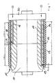
- Fig. 1 and 2 show a transfer cylinder 10 of a printing unit of a web-fed printing press according to the invention, in particular an illustration printing press, wherein the transfer cylinder 10 is assigned a transmission system 11 is soft on an outer surface 12 of the transfer cylinder 10 is arranged or pushed onto this outer surface 12.
- the transmission system 11 comprises two rubber sleeves 13, 14 arranged side by side in the axial direction of the transfer cylinder 10.
- Fig. 1 shows the transfer cylinder 10 in a state in which both rubber sleeves 13, 14 are pushed onto the outer surface 12 thereof.
- Fig. 2 shows, however, the transfer cylinder 10 exclusively together with the rubber sleeve 14th
- Fig. 1 Transmission system 11 shown is divided so that a joint 15 between the directly juxtaposed rubber sleeves 13, 14 in the middle of the printing-used width L of the transfer cylinder 10 and the transmission system 11 is located.
- Each rubber sleeve 13, 14 therefore has a printing width of% L.
- the joint 15 between the two rubber sleeves 13, 14, which are positioned next to each other on the transfer cylinder 10 in the axial direction, is located at a non-printing location or a non-printing axial position of the transfer cylinder 10, in particular at an axial position of a longitudinal fold to be formed on the printed substrate and / or longitudinal section.
- an independent compressed air system 16 or 17 is integrated into the transfer cylinder 10 for each rubber sleeve 13, 14 ,
- the compressed air system 16 has air openings 18 and the compressed air system 17 via air openings 19, which respectively open on the outer surface 12 of the transfer cylinder 10.
- An air pressure p can be provided to the compressed air system 16 in order to build up an air cushion when mounting or dismounting or removing the rubber sleeves 13, 14 between the surface 12 of the transfer cycle 10 and the respective rubber sleeve 13, 14.
- the opening on the surface of the transfer cylinder 10 air holes 18, 19 of the compressed air systems 16, 17 are spaced apart such that the axial distance between the air holes 18, 19 of the two compressed air systems 16, 17 is either smaller or equal to the axial extent of the Rubber sleeves 13, 14. This may work best Fig. 2 taken from the rubber sleeve 14 when mounting or dismounting the same on the transfer cylinder 10.
- Fig. 2 So shows Fig. 2 in that the rubber sleeve 14 covers both the air bores 18 of the compressed air system 16 and the air bores 19 of the compressed air system 17 in the position shown. This ensures that when mounting or mounting and dismounting or removing the air cushion between the rubber sleeve 14 and the outer surface 12 of the transfer cylinder 10 does not depart.
- the air holes 18, 19 have in the assembled state of the two rubber sleeves 13, 14 from a seen in the lift direction rear edge of the rubber sleeves 13, 14 a defined distance A and B on.
- the forme cylinder 10 has a portion 20 which protrudes relative to the outer surface 12 and thus forms a stop for the front rubber sleeve 14 seen in the lift direction.
- the transfer cylinder associated transmission system comprises a plurality of rubber sleeves.
- the transfer cylinder associated transmission system comprises a plurality of rubber sleeves.
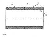
- a continuous carrier sleeve 30 eg made of nickel
- two or more rubber hoists 31 are closed by seals 32.
- seals 32 it is advantageous simply possible to produce rubber tires with narrow width a wider overall sleeve.
- the inventive concept is not limited to transfer cylinders and transmission systems, but the invention can also be used in Formzytindern and printing plate systems.
- the above explanations apply analogously to pressure-forming systems designed in several parts in the axial direction of a forme cylinder, in which case the pressure-forming systems preferably comprise a plurality of shaping sleeves positioned next to one another in the axial direction.
- the form cylinder is preferably associated with a continuous clamping channel without offset for receiving the multi-part printing form system.
- Each of the part-width printing plates preferably has a mechanical register system which is accommodated in the forme cylinder.
- the clamping channel accommodates a clamping or clamping system for the printing plates.
- the deviation of the outer diameter is up to 0.04 millimeters. This can lead to different conveying behavior and wrinkling on the paper web when several such rubber sleeves are used together on a transfer cylinder of an offset printing press, in particular at the joints of two rubber sleeves. Especially with large web tension, as is usually the case with commercial printing presses, such wrinkles can also lead to web breaks. Web breaks can damage the press and in any case lead to downtime.
- the outer rubber layer is usually ground to achieve a predetermined surface roughness and a given dimension for the diameter.
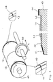
- the (two or more) rubber sleeves 13, 14 to be used together are received together on a so-called master cylinder 40 and ground together by a grinding device 50 to the predetermined diameter and finished therewith.
- Corresponding devices for finishing rubber sleeve or rubber sleeves are well known.
- the master cylinder 40 is preferably rotatably mounted on both sides, wherein at least one storage for the assembly or disassembly of sleeves can be removed.
- the master cylinder 40 is preferably provided with an air system that can create an air cushion under a sleeve.
- the grinding device 50 is vorzumik from a rotating grinding wheel 50, which is on the surface of the mother cylinder 40 on and off.
- the grinding device 50 moves under the action of the surface of the rubber sleeves 13, 14 in the axial direction (arrow A) over the entire length of the mounted rubber sleeves 13,14, possibly also in addition with an overflow.
- the grinding operation is preferably carried out in synchronism, ie, the rotation of the nut cylinder 40 and the direction of rotation of the grinding wheel 50 run at the contact point in the same direction. Of course, a reverse grinding would be possible.
- the two or more rubber sleeves have an identical outer diameter and an identical surface roughness so that a homogeneous web tension is ensured and wrinkling of the paper web is avoided.
- the rubber sleeves 13, 14, which have been finished together, must be marked accordingly are used and together on a transfer cylinder of a printing press.
- the already existing on the metallic inner sleeve marking preferably supplemented by a corresponding reference to a pairwise production or more sleeves. Since during finishing, despite the greatest care over the processing length slight differences in diameter (within the tolerance limits) may occur, it is particularly advantageous if the rubber sleeves are applied in exactly the mounting position on the transfer cylinder, which they had also taken during the finishing. That is, the rubber sleeves are preferably mounted with the same end sides as in the finishing machining against each other on a transfer or blanket cylinder. At the rubber sleeves 13, 14 corresponding labels are provided. For this example, small grooves 42, 43 are arranged in non-printing area of the sleeves.
- the rubber sleeves are preferably aligned with respect to their circumferential position so on the transfer cylinder / blanket cylinder to each other that it corresponds to the circumferential position on the master cylinder during finishing.
- markings are preferably applied to the rubber sleeves 13, 14 and the master cylinder 40 as well as the blanket cylinders of the printing press. Such markings may for example be designed as dashes 41, 44 on the master cylinder and rubber or transfer cylinder or as small grooves, comparable to those on the rubber sleeves.
Landscapes
- Engineering & Computer Science (AREA)
- Mechanical Engineering (AREA)
- Rotary Presses (AREA)
Applications Claiming Priority (2)
| Application Number | Priority Date | Filing Date | Title |
|---|---|---|---|
| DE102007022000 | 2007-05-08 | ||
| DE102007047781A DE102007047781A1 (de) | 2007-05-08 | 2007-10-05 | Rollendruckmaschine |
Publications (2)
| Publication Number | Publication Date |
|---|---|
| EP1990191A2 true EP1990191A2 (fr) | 2008-11-12 |
| EP1990191A3 EP1990191A3 (fr) | 2010-12-01 |
Family
ID=39656474
Family Applications (1)
| Application Number | Title | Priority Date | Filing Date |
|---|---|---|---|
| EP08008639A Withdrawn EP1990191A3 (fr) | 2007-05-08 | 2008-05-08 | Presse d'impression rotative pour bandes |
Country Status (1)
| Country | Link |
|---|---|
| EP (1) | EP1990191A3 (fr) |
Cited By (1)
| Publication number | Priority date | Publication date | Assignee | Title |
|---|---|---|---|---|
| EP2116375A2 (fr) | 2008-05-08 | 2009-11-11 | manroland AG | Presse rotative |
Families Citing this family (1)
| Publication number | Priority date | Publication date | Assignee | Title |
|---|---|---|---|---|
| CN106218202B (zh) * | 2016-07-28 | 2018-08-21 | 浙江汇锋薄膜科技有限公司 | 一种装饰膜制备设备中的印刷辊筒 |
Family Cites Families (14)
| Publication number | Priority date | Publication date | Assignee | Title |
|---|---|---|---|---|
| US1576726A (en) * | 1924-04-24 | 1926-03-16 | Arthur B Davis | Printing roller and method of making same |
| US2525003A (en) * | 1947-11-17 | 1950-10-10 | Commercial Lithograph Company | Method of making lithograph blankets |
| GB659617A (en) * | 1948-05-01 | 1951-10-24 | Dewey And Almy Chem Comp | Textile print blankets and the like |
| US3006277A (en) * | 1959-05-15 | 1961-10-31 | Kidder Press Company Inc | Plate cylinders for printing presses |
| US3696745A (en) * | 1971-01-22 | 1972-10-10 | Jay Morton | Composite offset printing plate |
| DE3336193C2 (de) * | 1983-10-05 | 1986-02-27 | M.A.N.- Roland Druckmaschinen AG, 6050 Offenbach | Gummituch für eine Offsetrotationsdruckmaschine |
| US4899657A (en) * | 1987-01-12 | 1990-02-13 | Mitsubishi Paper Mills, Ltd. | Method for preventing penetration of damping solution between supporting base and plate |
| SE9101235L (sv) * | 1991-04-23 | 1992-10-24 | Miller Graphics Ab | Anordning vid tryckverk |
| US6374731B1 (en) * | 1997-04-18 | 2002-04-23 | Heidelberger Druckmaschinen Ag | Lithographic newspaper printing press |
| DE19803809A1 (de) * | 1998-01-31 | 1999-08-05 | Roland Man Druckmasch | Offsetdruckwerk |
| DE19911180C2 (de) * | 1999-03-12 | 2001-02-01 | Koenig & Bauer Ag | Druckwerk für eine Rotationsdruckmaschine |
| DE10135506A1 (de) * | 2000-07-28 | 2002-02-07 | Heidelberger Druckmasch Ag | Plattenzylinder zur Aufnahme mehrerer Druckplatten |
| US7107907B2 (en) * | 2001-01-22 | 2006-09-19 | Goss International Americas, Inc. | Flow-restricted printing cylinder for a removable printing sleeve |
| US20050229800A1 (en) * | 2004-04-20 | 2005-10-20 | Heidelberger Druckmaschinen Ag | Plate cylinder with larger diameter central image area |
-
2008
- 2008-05-08 EP EP08008639A patent/EP1990191A3/fr not_active Withdrawn
Cited By (2)
| Publication number | Priority date | Publication date | Assignee | Title |
|---|---|---|---|---|
| EP2116375A2 (fr) | 2008-05-08 | 2009-11-11 | manroland AG | Presse rotative |
| EP2116375A3 (fr) * | 2008-05-08 | 2010-02-24 | manroland AG | Presse rotative |
Also Published As
| Publication number | Publication date |
|---|---|
| EP1990191A3 (fr) | 2010-12-01 |
Similar Documents
| Publication | Publication Date | Title |
|---|---|---|
| EP0990518B1 (fr) | Cylindre d'une machine à imprimer, notamment cylindre de contre-pression pour une machine à imprimer à feuilles rotative | |
| EP0549936B1 (fr) | Cylindre de transfert avec manchon échangeable, supporté entre deux parois latérales d'un élément d'impression | |
| EP1157855B1 (fr) | Manchon à base de caoutchouc, notamment pour machines rotatives offset | |
| DE19756942C2 (de) | Druckmaschinenzylinder, insbesondere Gegendruckzylinder für eine Bogenrotationsdruckmaschine | |
| DE4404758C2 (de) | Verfahren und Vorrichtung zum Wechseln der Bespannung eines Zylinders einer Rollenrotationsdruckmaschine | |
| EP1707355B1 (fr) | Unité d'impression d'une machine d'impression sans dispositif de mouillage | |
| EP1176008A1 (fr) | Machine d'impression à plusieurs couleurs avec un cylindre de blanchet commun | |
| EP0150355B1 (fr) | Procédé d'impression à retiration et machine d'impression offset à feuilles pour la mise en oeuvre du procédé | |
| DE10237205B4 (de) | Aufzug auf einer Walze, Anordnungen der Walze zu einer zweiten Walze sowie Druckwerke einer Druckmaschine mit der Walze | |
| EP1990191A2 (fr) | Presse d'impression rotative pour bandes | |
| EP1917142A1 (fr) | Systeme et procede pour changer une longueur d'impression | |
| EP1967360B1 (fr) | Manchon et outil de serrage destinés à l'utilisation dans un système constitué d'un outil de serrage et d'au moins un manchon | |
| EP1136265A9 (fr) | Unité d'impression dans une machine d'impression | |
| DE19926410A1 (de) | Gummituchzylinder in einer Rotationsdruckmaschine | |
| DE19848390B4 (de) | Rollenrotationsdruckmaschine für einen schnellen Produktionswechsel | |
| DE102007047781A1 (de) | Rollendruckmaschine | |
| DE102009000573A1 (de) | Verfahren und Vorrichtung zur Veredelung eines Bedruckstoffes in einer Verarbeitungsmaschine | |
| DE19647067A1 (de) | Rotationsdruckmaschine | |
| EP1724114B1 (fr) | Machine d'impression rotative avec au moins un groupe d'impression | |
| DE4328027A1 (de) | Rotationsdruckmaschine zum Herstellen von Zeitungen | |
| CH655055A5 (de) | Sammeldruck-rotationsmaschinendruckwerk fuer wertpapierdruck. | |
| EP0687562B1 (fr) | Méthode et appareil pour le montage de plaques d'impression flexibles | |
| DE19718549B4 (de) | Druckmaschine | |
| DE102013103712A1 (de) | Druckwerk und Gummituchplatte für ein Druckwerk | |
| EP3653382B1 (fr) | Dispositif de palier détachable d'un cylindre d'encrage d'une machine d'impression |
Legal Events
| Date | Code | Title | Description |
|---|---|---|---|
| PUAI | Public reference made under article 153(3) epc to a published international application that has entered the european phase |
Free format text: ORIGINAL CODE: 0009012 |
|
| AK | Designated contracting states |
Kind code of ref document: A2 Designated state(s): AT BE BG CH CY CZ DE DK EE ES FI FR GB GR HR HU IE IS IT LI LT LU LV MC MT NL NO PL PT RO SE SI SK TR |
|
| AX | Request for extension of the european patent |
Extension state: AL BA MK RS |
|
| PUAL | Search report despatched |
Free format text: ORIGINAL CODE: 0009013 |
|
| AK | Designated contracting states |
Kind code of ref document: A3 Designated state(s): AT BE BG CH CY CZ DE DK EE ES FI FR GB GR HR HU IE IS IT LI LT LU LV MC MT NL NO PL PT RO SE SI SK TR |
|
| AX | Request for extension of the european patent |
Extension state: AL BA MK RS |
|
| RIC1 | Information provided on ipc code assigned before grant |
Ipc: B41N 10/04 20060101ALI20101022BHEP Ipc: B41F 13/193 20060101AFI20080809BHEP |
|
| 17P | Request for examination filed |
Effective date: 20110530 |
|
| AKX | Designation fees paid |
Designated state(s): AT BE BG CH CY CZ DE DK EE ES FI FR GB GR HR HU IE IS IT LI LT LU LV MC MT NL NO PL PT RO SE SI SK TR |
|
| 19U | Interruption of proceedings before grant |
Effective date: 20120201 |
|
| 19W | Proceedings resumed before grant after interruption of proceedings |
Effective date: 20140203 |
|
| STAA | Information on the status of an ep patent application or granted ep patent |
Free format text: STATUS: THE APPLICATION HAS BEEN WITHDRAWN |
|
| 18W | Application withdrawn |
Effective date: 20140311 |