EP1990197B1 - Procédé d'ajustement automatisé de la compression d'un corps de rotation dans une machine d'impression - Google Patents
Procédé d'ajustement automatisé de la compression d'un corps de rotation dans une machine d'impression Download PDFInfo
- Publication number
- EP1990197B1 EP1990197B1 EP08103604.8A EP08103604A EP1990197B1 EP 1990197 B1 EP1990197 B1 EP 1990197B1 EP 08103604 A EP08103604 A EP 08103604A EP 1990197 B1 EP1990197 B1 EP 1990197B1
- Authority
- EP
- European Patent Office
- Prior art keywords
- rotary body
- pressure
- pressure strip
- rotary
- image
- Prior art date
- Legal status (The legal status is an assumption and is not a legal conclusion. Google has not performed a legal analysis and makes no representation as to the accuracy of the status listed.)
- Not-in-force
Links
- 238000000034 method Methods 0.000 title claims description 38
- 238000007639 printing Methods 0.000 title claims description 21
- 238000003825 pressing Methods 0.000 title description 26
- 238000005259 measurement Methods 0.000 claims description 14
- 230000000694 effects Effects 0.000 claims description 6
- 230000003068 static effect Effects 0.000 claims description 5
- 239000000463 material Substances 0.000 claims description 4
- 238000007645 offset printing Methods 0.000 description 9
- 238000011161 development Methods 0.000 description 8
- 230000018109 developmental process Effects 0.000 description 8
- 239000000758 substrate Substances 0.000 description 4
- 238000012546 transfer Methods 0.000 description 4
- 230000005693 optoelectronics Effects 0.000 description 3
- 230000002093 peripheral effect Effects 0.000 description 3
- 238000012937 correction Methods 0.000 description 2
- 239000012530 fluid Substances 0.000 description 2
- 230000009291 secondary effect Effects 0.000 description 2
- 238000005406 washing Methods 0.000 description 2
- 230000002411 adverse Effects 0.000 description 1
- 230000009849 deactivation Effects 0.000 description 1
- 230000001419 dependent effect Effects 0.000 description 1
- 238000009826 distribution Methods 0.000 description 1
- 230000003993 interaction Effects 0.000 description 1
- 230000001105 regulatory effect Effects 0.000 description 1
- 230000000284 resting effect Effects 0.000 description 1
- 230000000717 retained effect Effects 0.000 description 1
- 238000005096 rolling process Methods 0.000 description 1
- 238000003860 storage Methods 0.000 description 1
Images


Classifications
-
- B—PERFORMING OPERATIONS; TRANSPORTING
- B41—PRINTING; LINING MACHINES; TYPEWRITERS; STAMPS
- B41F—PRINTING MACHINES OR PRESSES
- B41F33/00—Indicating, counting, warning, control or safety devices
- B41F33/0072—Devices for measuring the pressure between cylinders or bearer rings
-
- B—PERFORMING OPERATIONS; TRANSPORTING
- B41—PRINTING; LINING MACHINES; TYPEWRITERS; STAMPS
- B41F—PRINTING MACHINES OR PRESSES
- B41F31/00—Inking arrangements or devices
- B41F31/30—Arrangements for tripping, lifting, adjusting, or removing inking rollers; Supports, bearings, or forks therefor
- B41F31/304—Arrangements for inking roller bearings, forks or supports
- B41F31/308—Swinging bearings
-
- B—PERFORMING OPERATIONS; TRANSPORTING
- B41—PRINTING; LINING MACHINES; TYPEWRITERS; STAMPS
- B41F—PRINTING MACHINES OR PRESSES
- B41F33/00—Indicating, counting, warning, control or safety devices
- B41F33/0036—Devices for scanning or checking the printed matter for quality control
Definitions
- the present invention relates to a method for the automated adjustment of a rotational body pressure in a printing press, wherein a press strip image measurement is carried out on a printing material, according to the preamble of claim 1.
- rollers and cylinders When setting up a printing machine, their adjacent rollers and cylinders must be adjusted so that the existing in the nips between them pressing has the required level. Since of the two each forming a nip rotational bodies, d. H. Rollers or cylinders, usually at least one has a rubber-elastic peripheral surface, the latter is flattened as a result of the pressure. This flattening is also referred to as a contact or pressing strip and has a width to be measured transversely to the roll rotation axis, the so-called pressing strip width.
- the press strip width can serve as a measure of the set pressure and be measured in various ways.
- the measured variable for the control is the color density, which is measured online or offline with a densitometer.
- the nip width produced in a nip between a fountain roller and a plate cylinder is measured from a nip image which has been transferred to the signature.
- the measurement of the press strip image is done by optoelectronic scanning.
- the measuring signals of the used sensor optoelectronic scanning are transmitted to a control or regulating device, which generates therefrom control signals for driving an actuator, which adjusts the inking roller such that between the latter and the plate cylinder the required pressure is present.
- the invention is therefore based on the object of specifying a roll adjustment method which meets the complexity of roller inking.
- the method according to the invention for the automatic adjustment of a rotational body pressure in a printing press, wherein a press strip image measurement is performed on a printing material is characterized in that an image of a first press strip, which is formed by a first rotary body together with a second rotary body, and an image of a second pressing strip, which is formed by the second rotary body together with a third rotary body, are measured, and that the rotary body pressing is automatically adjusted.
- This method does justice to the complexity of modern roller inking systems because it allows for consideration of the interactions therein.
- a first servo motor and a second servo motor are controlled by an electronic control device as a function of measuring signals of a measuring device for measuring the two images of the two pressing strips in order to adjust the pressing strips.
- a first Actuator in the main effect or primarily the second pressing strip and set in secondary effect or secondarily the first pressing strip.
- this can be done by the second Actuator in the main effect or primarily the first pressing strip and in the secondary effect or secondarily the second pressing strip can be adjusted.
- the second rotary body and the third rotary body are adjusted by the two servo motors in a position relative to the first rotary body, in which a common center centers of the first body of rotation and the second body of revolution and a common center of the second center of rotation and the third body of revolution non-rectangular angle greater than 0 ° and less than 180 °.
- a final target value of the width of the first press strip and a final target value of the width of the second press strip are set based on the measurement of only the image of the first press strip and the image of the second press strip and no further image of the two press strips.
- the final target value of the width of the first press strip and the final target value of the width of the second press strip is set by a single measurement of the images subsequent to the first servo motor and a single image motor subsequent to the second motor.
- a forme cylinder is used as the first rotary body, an inking roller as the second rotary body, and a rubbing roller as the third rotary body.
- the two images are measured on one and the same sheet.
- the two pressing strips are static pressing strips, which are generated in the case of rotary standstill of the rotating bodies between them.
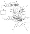
- FIG. 1 shows a first rotary body 1, a second rotary body 2 and a third rotary body 3 as components of a printing machine 4.
- the first rotary body 1 is a forme cylinder for lithographic offset printing.
- the second rotary body 2 is an inking roller with rubber-elastic peripheral surface and is located in the printing operation on the first rotary body 1 at.
- the third rotary body 3 is a friction roller, which is axially oscillated and provided with a coaxial drive gear, and abuts against the second rotary body 2.
- a common, first center center 11 of the first and second rotating bodies 1, 2 and a common, second center center 12 of the second and third rotating bodies 2, 3 close one Angle ⁇ a.
- the angle ⁇ between the central centers 11, 12 is greater than 0 ° and less than 180 °, but not a right angle, but an obtuse angle.
- a third lever 23 is fixed to the first lever 21, in which a roller 16 is rotatably mounted, which is supported on a cam 17.
- an electric, first servomotor 31 for pivoting the second lever 22 about the pivot joint 14 is arranged on the second lever 22.
- the first servomotor 31 engages via a worm gear 18 on a first arm of the second lever 22.
- the second rotary body 2 is mounted on a second arm of the second lever 22 .
- an electric, second actuator 32 is attached, which acts via a further worm gear 19 on the third lever 23 to pivot the latter together with the roller 16 mounted therein about the hinge 15.
- the first lever 21 is pivoted about the center 13 of the third rotary body 3.
- the actuation of the second servomotor 32 serves the pressure in a common, first nip 41 (see. FIG. 2 ) of the first and second rotary bodies 1, 2 to dose the fluid or color quantity transferred from the second rotary body 2 to the first rotary body 1.
- the actuation of the first servomotor 31 serves to reduce the pressure in a common, second nip 42 (cf. FIG. 2 ) of the second and third rotating bodies 2, 3 to dose the quantity of fluid or ink transferred from the third rotating body 3 to the second rotating body 2.
- the angle ⁇ is not a right angle, it is structurally unavoidable that the actuation of the first actuator 31 not only causes the desired adjustment of a press strip width b in the second nip 42, but also as an undesirable side effect on the size of a Press strip width a in the first nip 41 effects.
- FIG. 2 shows the trigonometric conditions of the storage of the rotating body 1, 2 and 3 in a schematic representation. It can be seen that the size of the angle ⁇ deviating from 90 ° necessarily means that the adjustment of the roll provision made for the second nip 42 adversely affects the roll provision in the first nip 41.
- FIG. 3 shows a flow chart of a method for automatic roll adjustment.
- the start takes place.
- a washing of the inking unit comprising the second and third rotary bodies 2, 3 and of the printing unit, which in addition to the first rotary body 1 also comprises a blanket cylinder resting against the first rotary body 1 in the printing operation is carried out first.
- the method step 51 includes that at a Farbzonendosier worn a color box of the inking the metering, z. B. metering with zone screws, are set so that all ink zones are the same wide open and over the print width in all ink zones an equal amount of ink is metered.
- an inlet of the ink from the ink fountain into the inking unit wherein in this ink inlet an inking unit coordinated dampening unit is inactive.
- the roll adjustment process is performed immediately after a print job is performed, the washing, the uniform adjustment of the ink zone openings, and the ink feed can be omitted. In this case, only the dampening unit is deactivated, so that it no longer promotes dampening solution.
- the inking rollers will become including the second rotary body 2 and a dampening roller of the dampening unit to the first rotary body 1 employed to transfer the ink from the inking unit to the first rotary body 1 and the offset printing form located thereon.
- This transfer of color takes place without a transfer of the dampening solution to the offset printing form, so that the latter also assumes the printing ink in the non-printing, hydrophilic areas, which would otherwise be kept free of color by the dampening solution. Therefore, in the process variant in which the roll adjustment takes place immediately following the execution of the print job, in the roll adjustment that offset printing form on the first rotation body 1 which has been used for this print job can be retained.
- an offset printing forme which is specially provided for the roll adjustment, is clamped onto the first rotary body 1.
- This special offset printing form has a homogeneous print image, so that the deactivation of the dampening unit is not required.
- a static contact or pressing strip in the first nip 41 (cf. FIG. 2 ) and in a parallel process step 53, a static contact or pressure strip in the second nip 42 is generated.
- the rotation of the first rotary body 1 and the application rollers lying on the latter including the second rotary body 2 and the rotation of the third rotary body 3 is stopped in a rotational angular position in which the leading edge of the offset printing form immediately after the last in the direction of rotation of the first rotary body 1 of the inking rollers stands. Due to the standstill and the static pressure in the nips 41, 42, the ink is pressed out of these nips.
- the width of the pressing strips transmitted to the printed sheets is determined. For this purpose, the one selected from the printed 5 to 10 sheet on which the two pressing strips are best recognizable.
- the opto-electronic, z. B. densitometric, measuring device 24 For measuring the widths of the images of the pressing strips on the printing substrate 25, d. H. on the printed sheet with the clearest images, this is placed on a measuring table, the opto-electronic, z. B. densitometric, measuring device 24 has.
- FIG. 4 shows that this measuring device 24 is connected to an electronic control device 20, which in turn is connected to the servomotors 31, 32 (see. FIG. 1 ).
- the control device 20 calculates the required correction values of the employment of the second to the first rotation body and the employment of the second to the third rotation body in a method step 56.
- the control device 20 takes into account the fact already explained that the change in the setting of the second to the third rotary body entails a change in the setting of the second to the first rotary body.
- the correction calculation of the two jobs d. H. the center distances between the first and second rotation body and between the second and third rotation body, the influence of one of the other employment by the control means 20 based on stored therein mathematical formulas, for. B.
- a trigonometric context descriptive polynomial model or based on a stored in the control unit 20 table of values whose value pairs are determined in an analytical manner according to the aforementioned formula or are determined experimentally, or based on a corresponding function curve are taken into account.
- control device 20 controls the servo motors 31, 32 in such a way that in a method step 57, the second servomotor 32 moves to the newly calculated target value for setting the second to the first rotary body and in a simultaneous or parallel process step 58 of FIG first servomotor 31 moves the newly calculated target value of the employment of the second to the third rotary body.
Landscapes
- Engineering & Computer Science (AREA)
- Quality & Reliability (AREA)
- Inking, Control Or Cleaning Of Printing Machines (AREA)
- Rotary Presses (AREA)
Claims (9)
- Procédé pour l'ajustement automatisé de la compression d'un corps de rotation dans une machine d'impression (4), une mesure de image d'une bande de pression étant effectuée sur un support imprimé (25),
caractérisé en ce
qu'une image d'une première bande de pression qui est formée par un premier corps de rotation (1) ensemble avec un second corps de rotation (2), et une image d'une seconde bande de pression qui est formée par un second corps de rotation (2) ensemble avec un troisième corps de rotation (3), sont mesurées et en ce que la compression du corps de rotation est ajustée automatiquement. - Procédé selon la revendication 1,
caractérisé en ce
qu'un dispositif électronique de commande (20) commande un premier moteur de réglage (31) et un second moteur de réglage (32) en fonction de signaux de mesure d'un dispositif de mesure (24) pour la mesure des largeurs des images des deux bandes de pression pour régler les bandes de pression. - Procédé selon la revendication 2,
caractérisé en ce
que le premier moteur de réglage (31) règle, en effet principal ou primaire, la seconde bande de pression et, en effet annexe ou secondaire, la première bande de mesure. - Procédé selon la revendication 2 ou 3,
caractérisé en ce que
les deux moteurs de réglage (31, 32) amènent le second corps de rotation (2) et le troisième corps de rotation (3) dans une position par rapport au second corps de rotation (1), dans laquelle un point commun central (11) du premier corps de rotation (1) et du second corps de rotation (2) et un point central commun (12) du second corps de rotation (2) et du troisième corps de rotation (3) forment un angle non droit (α) supérieur à 0° et inférieur à 180°. - Procédé selon l'une des revendications 2 à 4,
caractérisé en ce
qu'une valeur cible définitive de la largeur de la première bande de mesure et une valeur cible définitive de la largeur de la seconde bande de mesure sont réglées uniquement sur la base de la mesure de l'image de la première bande de pression et de l'image de la seconde bande pression et d'aucune autre image des deux bandes de pression. - Procédé selon la revendication 1,
caractérisé en ce
qu'une valeur cible définitive de la largeur de la première bande de mesure et une valeur cible définitive de la largeur de la seconde bande de mesure sont réglées par un seul tour de du premier moteur de réglage (31) consécutif à la mesure des images et un seul tour du second moteur de réglage (32) consécutif à la mesure des images. - Procédé selon l'une des revendications 1 à 6,
caractérisé en ce
que le premier corps de rotation (1) est un cylindre de cliché, le corps de rotation (2) est un rouleau encreur et le troisième corps de rotation (3) un rouleau à friction. - Procédé selon l'une des revendications 1 à 7,
caractérisé en ce
que les deux images sont mesurées sur une seule et même feuille imprimée. - Procédé selon l'une des revendications 1 à 7,
caractérisé en ce
que les deux bandes de pression sont des bandes de pression statiques, qui sont générées entre les corps de rotation (1, 2, 3) au moment de leur immobilisation en rotation.
Applications Claiming Priority (1)
| Application Number | Priority Date | Filing Date | Title |
|---|---|---|---|
| DE102007022079A DE102007022079A1 (de) | 2007-05-11 | 2007-05-11 | Verfahren zum automatisierten Justieren einer Rotationskörperpressung in einer Druckmaschine |
Publications (4)
| Publication Number | Publication Date |
|---|---|
| EP1990197A2 EP1990197A2 (fr) | 2008-11-12 |
| EP1990197A3 EP1990197A3 (fr) | 2012-07-04 |
| EP1990197B1 true EP1990197B1 (fr) | 2016-11-02 |
| EP1990197B2 EP1990197B2 (fr) | 2020-04-29 |
Family
ID=39712377
Family Applications (1)
| Application Number | Title | Priority Date | Filing Date |
|---|---|---|---|
| EP08103604.8A Not-in-force EP1990197B2 (fr) | 2007-05-11 | 2008-04-18 | Procédé d'ajustement automatisé de la compression d'un corps de rotation dans une machine d'impression |
Country Status (3)
| Country | Link |
|---|---|
| US (1) | US20080276816A1 (fr) |
| EP (1) | EP1990197B2 (fr) |
| DE (1) | DE102007022079A1 (fr) |
Families Citing this family (5)
| Publication number | Priority date | Publication date | Assignee | Title |
|---|---|---|---|---|
| DE102010000907B4 (de) * | 2010-01-14 | 2015-09-10 | Windmöller & Hölscher Kg | Verfahren und Vorrichtung zum Optimieren der Relativposition zumindest zweier Druckwerkszylinder |
| IT1403496B1 (it) * | 2010-12-27 | 2013-10-17 | Uteco Converting Spa | Sistema e procedimento di regolazione e controllo delle pressioni di cilindri di stampa in una macchina da stampa flessografica a tamburo centrale |
| DE102017201600B4 (de) | 2017-02-01 | 2019-04-25 | Koenig & Bauer Ag | Verfahren zum Kontrollieren mehrerer Pressstreifen hinsichtlich ihrer jeweiligen Streifenbreite |
| WO2018029085A1 (fr) | 2016-08-09 | 2018-02-15 | Koenig & Bauer Ag | Procédé pour contrôler la largeur d'une bande de pression formée entre deux corps rotatifs d'un groupe d'impression |
| DE102016214713B4 (de) | 2016-08-09 | 2020-06-04 | Koenig & Bauer Ag | Verfahren zum Kontrollieren einer Streifenbreite eines Pressstreifens |
Citations (3)
| Publication number | Priority date | Publication date | Assignee | Title |
|---|---|---|---|---|
| DE4427967A1 (de) | 1993-08-24 | 1995-03-02 | Heidelberger Druckmasch Ag | Verfahren und Einrichtungen zur Zylinderdruckeinstellung zwischen farbführenden Zylindern einer Druckmaschine |
| DE10211870A1 (de) | 2001-03-29 | 2002-10-10 | Heidelberger Druckmasch Ag | Verfahren zur Justierung zweier aneinander anlegbarer Walzen eines Druckwerks und Druckwerk zur Durchführung eines derartigen Verfahrens |
| DE10145957A1 (de) | 2001-03-27 | 2002-10-17 | Windmoeller & Hoelscher | Vorrichtung und Verfahren zur Einstellung des Druckbildes in einer Flexodruckmaschine |
Family Cites Families (8)
| Publication number | Priority date | Publication date | Assignee | Title |
|---|---|---|---|---|
| DE4211379C2 (de) * | 1992-04-04 | 1999-01-07 | Roland Man Druckmasch | Anilox-Offset-Druckeinheit mit einem Kurzfarbwerk |
| DE4232163C3 (de) * | 1992-09-25 | 2001-09-06 | Koenig & Bauer Ag | Vorrichtung zum Aufrechterhalten einer eingestellten Anpressung einer Farbauftragswalze an einem Formzylinder einer Rotationsdruckmaschine |
| US5448949A (en) * | 1993-08-24 | 1995-09-12 | Heidelberger Druckmaschinen Ag | Method and device for adjusting a contact pressure between ink-carrying cylinders of a printing machine |
| JP4438155B2 (ja) * | 2000-01-31 | 2010-03-24 | 凸版印刷株式会社 | 印刷機のローラー調整方法とローラー調整装置、およびオフセット印刷機 |
| DE10302747A1 (de) * | 2003-01-24 | 2004-08-12 | Windmöller & Hölscher | Verfahren zur Korrektur von im Druckprozess auftretenden Schwankungen der auf das Druckbild übertragenen Farbmenge |
| US7225735B2 (en) * | 2004-05-03 | 2007-06-05 | Heidelberger Druckmaschinen Ag | Method for roller adjustment in a printing press |
| DE102005048367B4 (de) * | 2005-10-10 | 2010-08-05 | Wifag Maschinenfabrik Ag | Nip-Breitenmessung |
| US8931410B2 (en) * | 2006-01-25 | 2015-01-13 | Advanced Vision Technology (Avt) Ltd. | System and method for setting up a printing press |
-
2007
- 2007-05-11 DE DE102007022079A patent/DE102007022079A1/de not_active Withdrawn
-
2008
- 2008-04-18 EP EP08103604.8A patent/EP1990197B2/fr not_active Not-in-force
- 2008-05-12 US US12/119,040 patent/US20080276816A1/en not_active Abandoned
Patent Citations (3)
| Publication number | Priority date | Publication date | Assignee | Title |
|---|---|---|---|---|
| DE4427967A1 (de) | 1993-08-24 | 1995-03-02 | Heidelberger Druckmasch Ag | Verfahren und Einrichtungen zur Zylinderdruckeinstellung zwischen farbführenden Zylindern einer Druckmaschine |
| DE10145957A1 (de) | 2001-03-27 | 2002-10-17 | Windmoeller & Hoelscher | Vorrichtung und Verfahren zur Einstellung des Druckbildes in einer Flexodruckmaschine |
| DE10211870A1 (de) | 2001-03-29 | 2002-10-10 | Heidelberger Druckmasch Ag | Verfahren zur Justierung zweier aneinander anlegbarer Walzen eines Druckwerks und Druckwerk zur Durchführung eines derartigen Verfahrens |
Also Published As
| Publication number | Publication date |
|---|---|
| EP1990197A3 (fr) | 2012-07-04 |
| DE102007022079A1 (de) | 2008-11-13 |
| EP1990197B2 (fr) | 2020-04-29 |
| US20080276816A1 (en) | 2008-11-13 |
| EP1990197A2 (fr) | 2008-11-12 |
Similar Documents
| Publication | Publication Date | Title |
|---|---|---|
| EP1748892B1 (fr) | Procede pour reguler un transfert d'encre | |
| DE3435487C2 (fr) | ||
| DE10013876B4 (de) | Verfahren zum Regeln der Farbgebung beim Drucken mit einer Druckmaschine | |
| EP2097261B1 (fr) | Presse rotative et procédé pour ajuster un de ses cylindres | |
| DE102007008392B4 (de) | Integrierte Qualitätsregelung | |
| EP2759407B1 (fr) | Procédé de réglage et dispositif pour determiner la distance optimale entre au moins deux cylindres impliqués dans un procédé d'impression | |
| EP1820650B1 (fr) | Commande d'une presse à l'aide d'un modèle de torsion | |
| EP0393365B1 (fr) | Procédé et dispositif d'alimentation en liquide de mouillage d'une machine à imprimer en offset | |
| DE2845932A1 (de) | Kombiniertes feucht-farbwerk fuer offsetdruckwerke | |
| EP1990197B1 (fr) | Procédé d'ajustement automatisé de la compression d'un corps de rotation dans une machine d'impression | |
| DE4013003A1 (de) | Korrektur schraegliegender druckbilder | |
| EP1981791B1 (fr) | Dispositif et procédé de mesure et de réglage de la tension de bande entre des mécanismes d'encrage d'une machine d'impression polychrome | |
| DE10211870B4 (de) | Verfahren zur Justierung zweier aneinander anlegbarer Walzen eines Druckwerks | |
| EP1433596B1 (fr) | Méthode et appareil pour la mesure, la mise au point et l'ajustement du repérage latéral et longitudinal, ainsi que du repérage du parallélisme dans une machine d'impression multicouleur | |
| DE102009001302A1 (de) | Verfahren zum Betreiben einer Druckmaschine | |
| DE4218761A1 (de) | Verfahren zum Voreinstellen von Registereinstellvorrichtungen an Rotationsdruckmaschinen | |
| EP2762316B1 (fr) | Procédé de régulation d'un paramètre d'un dispositif d'encrage | |
| DE102010034350A1 (de) | Einrichtung zur Regelung des Feuchtmittelauftrags und Farbauftrags in einer Druckmaschine | |
| WO2004065127A2 (fr) | Procede pour corriger des variations de la quantite d'encre transferee sur l'image a imprimer qui apparaissent au cours de l'impression | |
| DE102008006192B4 (de) | Verfahren zum Betreiben einer Druckmaschine | |
| DE102007011344A1 (de) | Verfahren zur Farbmessung bei Druckmaschinen | |
| DE102007034835A1 (de) | Verfahren zum Betreiben einer wellenlosen Druckmaschine und wellenlose Druckmaschine | |
| DE102007044758B4 (de) | Verfahren zur Farbmessung und Farbregelung bei Druckmaschinen mittels internem und externem Farbmessgerät | |
| DE10110640A1 (de) | Verfahren zur Bebilderungskorrektur von Druckformen an Druckmaschinen | |
| DE102007063853B3 (de) | Integrierte Qualitätsregelung |
Legal Events
| Date | Code | Title | Description |
|---|---|---|---|
| PUAI | Public reference made under article 153(3) epc to a published international application that has entered the european phase |
Free format text: ORIGINAL CODE: 0009012 |
|
| AK | Designated contracting states |
Kind code of ref document: A2 Designated state(s): AT BE BG CH CY CZ DE DK EE ES FI FR GB GR HR HU IE IS IT LI LT LU LV MC MT NL NO PL PT RO SE SI SK TR |
|
| AX | Request for extension of the european patent |
Extension state: AL BA MK RS |
|
| RIN1 | Information on inventor provided before grant (corrected) |
Inventor name: SCHAFFRATH, DIETER Inventor name: LUCKHARDT, ULRICH Inventor name: DORENKAMP, FELIX Inventor name: HEILER, PETER Inventor name: MAYER, MARTIN |
|
| PUAL | Search report despatched |
Free format text: ORIGINAL CODE: 0009013 |
|
| RIC1 | Information provided on ipc code assigned before grant |
Ipc: B41F 31/30 20060101ALI20120522BHEP Ipc: B41F 33/00 20060101AFI20120522BHEP |
|
| AK | Designated contracting states |
Kind code of ref document: A3 Designated state(s): AT BE BG CH CY CZ DE DK EE ES FI FR GB GR HR HU IE IS IT LI LT LU LV MC MT NL NO PL PT RO SE SI SK TR |
|
| AX | Request for extension of the european patent |
Extension state: AL BA MK RS |
|
| RIC1 | Information provided on ipc code assigned before grant |
Ipc: B41F 31/30 20060101ALI20120529BHEP Ipc: B41F 33/00 20060101AFI20120529BHEP |
|
| 17P | Request for examination filed |
Effective date: 20130104 |
|
| AKX | Designation fees paid |
Designated state(s): AT BE BG CH CY CZ DE DK EE ES FI FR GB GR HR HU IE IS IT LI LT LU LV MC MT NL NO PL PT RO SE SI SK TR |
|
| GRAP | Despatch of communication of intention to grant a patent |
Free format text: ORIGINAL CODE: EPIDOSNIGR1 |
|
| INTG | Intention to grant announced |
Effective date: 20160316 |
|
| GRAS | Grant fee paid |
Free format text: ORIGINAL CODE: EPIDOSNIGR3 |
|
| GRAJ | Information related to disapproval of communication of intention to grant by the applicant or resumption of examination proceedings by the epo deleted |
Free format text: ORIGINAL CODE: EPIDOSDIGR1 |
|
| GRAP | Despatch of communication of intention to grant a patent |
Free format text: ORIGINAL CODE: EPIDOSNIGR1 |
|
| GRAS | Grant fee paid |
Free format text: ORIGINAL CODE: EPIDOSNIGR3 |
|
| GRAC | Information related to communication of intention to grant a patent modified |
Free format text: ORIGINAL CODE: EPIDOSCIGR1 |
|
| INTG | Intention to grant announced |
Effective date: 20160316 |
|
| GRAL | Information related to payment of fee for publishing/printing deleted |
Free format text: ORIGINAL CODE: EPIDOSDIGR3 |
|
| GRAS | Grant fee paid |
Free format text: ORIGINAL CODE: EPIDOSNIGR3 |
|
| GRAA | (expected) grant |
Free format text: ORIGINAL CODE: 0009210 |
|
| RIN1 | Information on inventor provided before grant (corrected) |
Inventor name: HEILER, PETER Inventor name: DORENKAMP, FELIX Inventor name: MAYER, MARTIN Inventor name: SCHAFFRATH, DIETER Inventor name: LUCKHARDT, ULRICH |
|
| AK | Designated contracting states |
Kind code of ref document: B1 Designated state(s): AT BE BG CH CY CZ DE DK EE ES FI FR GB GR HR HU IE IS IT LI LT LU LV MC MT NL NO PL PT RO SE SI SK TR |
|
| REG | Reference to a national code |
Ref country code: GB Ref legal event code: FG4D Free format text: NOT ENGLISH |
|
| REG | Reference to a national code |
Ref country code: AT Ref legal event code: REF Ref document number: 841419 Country of ref document: AT Kind code of ref document: T Effective date: 20161115 Ref country code: CH Ref legal event code: EP |
|
| REG | Reference to a national code |
Ref country code: IE Ref legal event code: FG4D Free format text: LANGUAGE OF EP DOCUMENT: GERMAN |
|
| REG | Reference to a national code |
Ref country code: DE Ref legal event code: R096 Ref document number: 502008014751 Country of ref document: DE |
|
| REG | Reference to a national code |
Ref country code: DE Ref legal event code: R081 Ref document number: 502008014751 Country of ref document: DE Owner name: HEIDELBERGER DRUCKMASCHINEN AG, DE Free format text: FORMER OWNER: HEIDELBERGER DRUCKMASCHINEN AKTIENGESELLSCHAFT, 69115 HEIDELBERG, DE |
|
| PG25 | Lapsed in a contracting state [announced via postgrant information from national office to epo] |
Ref country code: LV Free format text: LAPSE BECAUSE OF FAILURE TO SUBMIT A TRANSLATION OF THE DESCRIPTION OR TO PAY THE FEE WITHIN THE PRESCRIBED TIME-LIMIT Effective date: 20161102 |
|
| REG | Reference to a national code |
Ref country code: NL Ref legal event code: MP Effective date: 20161102 |
|
| REG | Reference to a national code |
Ref country code: LT Ref legal event code: MG4D |
|
| PG25 | Lapsed in a contracting state [announced via postgrant information from national office to epo] |
Ref country code: SE Free format text: LAPSE BECAUSE OF FAILURE TO SUBMIT A TRANSLATION OF THE DESCRIPTION OR TO PAY THE FEE WITHIN THE PRESCRIBED TIME-LIMIT Effective date: 20161102 Ref country code: GR Free format text: LAPSE BECAUSE OF FAILURE TO SUBMIT A TRANSLATION OF THE DESCRIPTION OR TO PAY THE FEE WITHIN THE PRESCRIBED TIME-LIMIT Effective date: 20170203 Ref country code: NO Free format text: LAPSE BECAUSE OF FAILURE TO SUBMIT A TRANSLATION OF THE DESCRIPTION OR TO PAY THE FEE WITHIN THE PRESCRIBED TIME-LIMIT Effective date: 20170202 Ref country code: LT Free format text: LAPSE BECAUSE OF FAILURE TO SUBMIT A TRANSLATION OF THE DESCRIPTION OR TO PAY THE FEE WITHIN THE PRESCRIBED TIME-LIMIT Effective date: 20161102 Ref country code: NL Free format text: LAPSE BECAUSE OF FAILURE TO SUBMIT A TRANSLATION OF THE DESCRIPTION OR TO PAY THE FEE WITHIN THE PRESCRIBED TIME-LIMIT Effective date: 20161102 |
|
| PG25 | Lapsed in a contracting state [announced via postgrant information from national office to epo] |
Ref country code: IS Free format text: LAPSE BECAUSE OF FAILURE TO SUBMIT A TRANSLATION OF THE DESCRIPTION OR TO PAY THE FEE WITHIN THE PRESCRIBED TIME-LIMIT Effective date: 20170302 Ref country code: HR Free format text: LAPSE BECAUSE OF FAILURE TO SUBMIT A TRANSLATION OF THE DESCRIPTION OR TO PAY THE FEE WITHIN THE PRESCRIBED TIME-LIMIT Effective date: 20161102 Ref country code: PT Free format text: LAPSE BECAUSE OF FAILURE TO SUBMIT A TRANSLATION OF THE DESCRIPTION OR TO PAY THE FEE WITHIN THE PRESCRIBED TIME-LIMIT Effective date: 20170302 Ref country code: ES Free format text: LAPSE BECAUSE OF FAILURE TO SUBMIT A TRANSLATION OF THE DESCRIPTION OR TO PAY THE FEE WITHIN THE PRESCRIBED TIME-LIMIT Effective date: 20161102 Ref country code: FI Free format text: LAPSE BECAUSE OF FAILURE TO SUBMIT A TRANSLATION OF THE DESCRIPTION OR TO PAY THE FEE WITHIN THE PRESCRIBED TIME-LIMIT Effective date: 20161102 Ref country code: PL Free format text: LAPSE BECAUSE OF FAILURE TO SUBMIT A TRANSLATION OF THE DESCRIPTION OR TO PAY THE FEE WITHIN THE PRESCRIBED TIME-LIMIT Effective date: 20161102 |
|
| REG | Reference to a national code |
Ref country code: DE Ref legal event code: R026 Ref document number: 502008014751 Country of ref document: DE |
|
| PG25 | Lapsed in a contracting state [announced via postgrant information from national office to epo] |
Ref country code: SK Free format text: LAPSE BECAUSE OF FAILURE TO SUBMIT A TRANSLATION OF THE DESCRIPTION OR TO PAY THE FEE WITHIN THE PRESCRIBED TIME-LIMIT Effective date: 20161102 Ref country code: CZ Free format text: LAPSE BECAUSE OF FAILURE TO SUBMIT A TRANSLATION OF THE DESCRIPTION OR TO PAY THE FEE WITHIN THE PRESCRIBED TIME-LIMIT Effective date: 20161102 Ref country code: EE Free format text: LAPSE BECAUSE OF FAILURE TO SUBMIT A TRANSLATION OF THE DESCRIPTION OR TO PAY THE FEE WITHIN THE PRESCRIBED TIME-LIMIT Effective date: 20161102 Ref country code: RO Free format text: LAPSE BECAUSE OF FAILURE TO SUBMIT A TRANSLATION OF THE DESCRIPTION OR TO PAY THE FEE WITHIN THE PRESCRIBED TIME-LIMIT Effective date: 20161102 Ref country code: DK Free format text: LAPSE BECAUSE OF FAILURE TO SUBMIT A TRANSLATION OF THE DESCRIPTION OR TO PAY THE FEE WITHIN THE PRESCRIBED TIME-LIMIT Effective date: 20161102 |
|
| PLBI | Opposition filed |
Free format text: ORIGINAL CODE: 0009260 |
|
| PG25 | Lapsed in a contracting state [announced via postgrant information from national office to epo] |
Ref country code: BG Free format text: LAPSE BECAUSE OF FAILURE TO SUBMIT A TRANSLATION OF THE DESCRIPTION OR TO PAY THE FEE WITHIN THE PRESCRIBED TIME-LIMIT Effective date: 20170202 Ref country code: IT Free format text: LAPSE BECAUSE OF FAILURE TO SUBMIT A TRANSLATION OF THE DESCRIPTION OR TO PAY THE FEE WITHIN THE PRESCRIBED TIME-LIMIT Effective date: 20161102 |
|
| PLAX | Notice of opposition and request to file observation + time limit sent |
Free format text: ORIGINAL CODE: EPIDOSNOBS2 |
|
| 26 | Opposition filed |
Opponent name: KOENIG & BAUER AG Effective date: 20170727 |
|
| PLBB | Reply of patent proprietor to notice(s) of opposition received |
Free format text: ORIGINAL CODE: EPIDOSNOBS3 |
|
| PG25 | Lapsed in a contracting state [announced via postgrant information from national office to epo] |
Ref country code: SI Free format text: LAPSE BECAUSE OF FAILURE TO SUBMIT A TRANSLATION OF THE DESCRIPTION OR TO PAY THE FEE WITHIN THE PRESCRIBED TIME-LIMIT Effective date: 20161102 |
|
| REG | Reference to a national code |
Ref country code: CH Ref legal event code: PL |
|
| GBPC | Gb: european patent ceased through non-payment of renewal fee |
Effective date: 20170418 |
|
| REG | Reference to a national code |
Ref country code: IE Ref legal event code: MM4A |
|
| REG | Reference to a national code |
Ref country code: FR Ref legal event code: ST Effective date: 20171229 |
|
| PG25 | Lapsed in a contracting state [announced via postgrant information from national office to epo] |
Ref country code: MC Free format text: LAPSE BECAUSE OF FAILURE TO SUBMIT A TRANSLATION OF THE DESCRIPTION OR TO PAY THE FEE WITHIN THE PRESCRIBED TIME-LIMIT Effective date: 20161102 Ref country code: FR Free format text: LAPSE BECAUSE OF NON-PAYMENT OF DUE FEES Effective date: 20170502 |
|
| PG25 | Lapsed in a contracting state [announced via postgrant information from national office to epo] |
Ref country code: LU Free format text: LAPSE BECAUSE OF NON-PAYMENT OF DUE FEES Effective date: 20170418 Ref country code: LI Free format text: LAPSE BECAUSE OF NON-PAYMENT OF DUE FEES Effective date: 20170430 Ref country code: CH Free format text: LAPSE BECAUSE OF NON-PAYMENT OF DUE FEES Effective date: 20170430 Ref country code: GB Free format text: LAPSE BECAUSE OF NON-PAYMENT OF DUE FEES Effective date: 20170418 |
|
| REG | Reference to a national code |
Ref country code: BE Ref legal event code: MM Effective date: 20170430 |
|
| PG25 | Lapsed in a contracting state [announced via postgrant information from national office to epo] |
Ref country code: IE Free format text: LAPSE BECAUSE OF NON-PAYMENT OF DUE FEES Effective date: 20170418 |
|
| PG25 | Lapsed in a contracting state [announced via postgrant information from national office to epo] |
Ref country code: BE Free format text: LAPSE BECAUSE OF NON-PAYMENT OF DUE FEES Effective date: 20170430 |
|
| REG | Reference to a national code |
Ref country code: AT Ref legal event code: MM01 Ref document number: 841419 Country of ref document: AT Kind code of ref document: T Effective date: 20170418 |
|
| PG25 | Lapsed in a contracting state [announced via postgrant information from national office to epo] |
Ref country code: AT Free format text: LAPSE BECAUSE OF NON-PAYMENT OF DUE FEES Effective date: 20170418 |
|
| PG25 | Lapsed in a contracting state [announced via postgrant information from national office to epo] |
Ref country code: MT Free format text: LAPSE BECAUSE OF FAILURE TO SUBMIT A TRANSLATION OF THE DESCRIPTION OR TO PAY THE FEE WITHIN THE PRESCRIBED TIME-LIMIT Effective date: 20161102 |
|
| PLAB | Opposition data, opponent's data or that of the opponent's representative modified |
Free format text: ORIGINAL CODE: 0009299OPPO |
|
| R26 | Opposition filed (corrected) |
Opponent name: KOENIG & BAUER AG Effective date: 20170727 |
|
| RAP2 | Party data changed (patent owner data changed or rights of a patent transferred) |
Owner name: HEIDELBERGER DRUCKMASCHINEN AG |
|
| PG25 | Lapsed in a contracting state [announced via postgrant information from national office to epo] |
Ref country code: HU Free format text: LAPSE BECAUSE OF FAILURE TO SUBMIT A TRANSLATION OF THE DESCRIPTION OR TO PAY THE FEE WITHIN THE PRESCRIBED TIME-LIMIT; INVALID AB INITIO Effective date: 20080418 |
|
| PG25 | Lapsed in a contracting state [announced via postgrant information from national office to epo] |
Ref country code: CY Free format text: LAPSE BECAUSE OF NON-PAYMENT OF DUE FEES Effective date: 20161102 |
|
| PUAH | Patent maintained in amended form |
Free format text: ORIGINAL CODE: 0009272 |
|
| STAA | Information on the status of an ep patent application or granted ep patent |
Free format text: STATUS: PATENT MAINTAINED AS AMENDED |
|
| PG25 | Lapsed in a contracting state [announced via postgrant information from national office to epo] |
Ref country code: TR Free format text: LAPSE BECAUSE OF FAILURE TO SUBMIT A TRANSLATION OF THE DESCRIPTION OR TO PAY THE FEE WITHIN THE PRESCRIBED TIME-LIMIT Effective date: 20161102 |
|
| 27A | Patent maintained in amended form |
Effective date: 20200429 |
|
| AK | Designated contracting states |
Kind code of ref document: B2 Designated state(s): AT BE BG CH CY CZ DE DK EE ES FI FR GB GR HR HU IE IS IT LI LT LU LV MC MT NL NO PL PT RO SE SI SK TR |
|
| REG | Reference to a national code |
Ref country code: DE Ref legal event code: R102 Ref document number: 502008014751 Country of ref document: DE |
|
| P01 | Opt-out of the competence of the unified patent court (upc) registered |
Effective date: 20230502 |
|
| PGFP | Annual fee paid to national office [announced via postgrant information from national office to epo] |
Ref country code: DE Payment date: 20230430 Year of fee payment: 16 |
|
| REG | Reference to a national code |
Ref country code: DE Ref legal event code: R119 Ref document number: 502008014751 Country of ref document: DE |
|
| PG25 | Lapsed in a contracting state [announced via postgrant information from national office to epo] |
Ref country code: DE Free format text: LAPSE BECAUSE OF NON-PAYMENT OF DUE FEES Effective date: 20241105 |
|
| PG25 | Lapsed in a contracting state [announced via postgrant information from national office to epo] |
Ref country code: DE Free format text: LAPSE BECAUSE OF NON-PAYMENT OF DUE FEES Effective date: 20241105 |