EP1990214A1 - Felge und Fahrrad mit Flügeln mit Schleifausgleich - Google Patents
Felge und Fahrrad mit Flügeln mit Schleifausgleich Download PDFInfo
- Publication number
- EP1990214A1 EP1990214A1 EP08005649A EP08005649A EP1990214A1 EP 1990214 A1 EP1990214 A1 EP 1990214A1 EP 08005649 A EP08005649 A EP 08005649A EP 08005649 A EP08005649 A EP 08005649A EP 1990214 A1 EP1990214 A1 EP 1990214A1
- Authority
- EP
- European Patent Office
- Prior art keywords
- wings
- rim
- areas
- axial distance
- wheel
- Prior art date
- Legal status (The legal status is an assumption and is not a legal conclusion. Google has not performed a legal analysis and makes no representation as to the accuracy of the status listed.)
- Withdrawn
Links
- 238000000034 method Methods 0.000 claims description 47
- 239000002184 metal Substances 0.000 claims description 12
- 229910052751 metal Inorganic materials 0.000 claims description 12
- 239000000463 material Substances 0.000 claims description 6
- 238000005452 bending Methods 0.000 claims description 3
- 230000000694 effects Effects 0.000 description 57
- 238000003466 welding Methods 0.000 description 9
- DOSMHBDKKKMIEF-UHFFFAOYSA-N 2-[3-(diethylamino)-6-diethylazaniumylidenexanthen-9-yl]-5-[3-[3-[4-(1-methylindol-3-yl)-2,5-dioxopyrrol-3-yl]indol-1-yl]propylsulfamoyl]benzenesulfonate Chemical compound C1=CC(=[N+](CC)CC)C=C2OC3=CC(N(CC)CC)=CC=C3C(C=3C(=CC(=CC=3)S(=O)(=O)NCCCN3C4=CC=CC=C4C(C=4C(NC(=O)C=4C=4C5=CC=CC=C5N(C)C=4)=O)=C3)S([O-])(=O)=O)=C21 DOSMHBDKKKMIEF-UHFFFAOYSA-N 0.000 description 8
- 239000002131 composite material Substances 0.000 description 8
- 238000003490 calendering Methods 0.000 description 7
- 239000007769 metal material Substances 0.000 description 5
- 210000000080 chela (arthropods) Anatomy 0.000 description 4
- 238000001125 extrusion Methods 0.000 description 4
- 238000005304 joining Methods 0.000 description 4
- 230000009977 dual effect Effects 0.000 description 3
- 238000003780 insertion Methods 0.000 description 3
- 230000037431 insertion Effects 0.000 description 3
- 238000000465 moulding Methods 0.000 description 3
- 239000004411 aluminium Substances 0.000 description 2
- 229910052782 aluminium Inorganic materials 0.000 description 2
- XAGFODPZIPBFFR-UHFFFAOYSA-N aluminium Chemical compound [Al] XAGFODPZIPBFFR-UHFFFAOYSA-N 0.000 description 2
- 230000007423 decrease Effects 0.000 description 2
- 238000009826 distribution Methods 0.000 description 2
- 238000003754 machining Methods 0.000 description 2
- OKTJSMMVPCPJKN-UHFFFAOYSA-N Carbon Chemical compound [C] OKTJSMMVPCPJKN-UHFFFAOYSA-N 0.000 description 1
- 102000015933 Rim-like Human genes 0.000 description 1
- 108050004199 Rim-like Proteins 0.000 description 1
- 238000004026 adhesive bonding Methods 0.000 description 1
- 210000000746 body region Anatomy 0.000 description 1
- 229910052799 carbon Inorganic materials 0.000 description 1
- 238000010276 construction Methods 0.000 description 1
- 238000004132 cross linking Methods 0.000 description 1
- 238000005520 cutting process Methods 0.000 description 1
- 239000000835 fiber Substances 0.000 description 1
- 239000002657 fibrous material Substances 0.000 description 1
- 239000011159 matrix material Substances 0.000 description 1
- 230000002093 peripheral effect Effects 0.000 description 1
- 239000000126 substance Substances 0.000 description 1
Images










Classifications
-
- B—PERFORMING OPERATIONS; TRANSPORTING
- B60—VEHICLES IN GENERAL
- B60B—VEHICLE WHEELS; CASTORS; AXLES FOR WHEELS OR CASTORS; INCREASING WHEEL ADHESION
- B60B21/00—Rims
- B60B21/06—Rims characterised by means for attaching spokes, i.e. spoke seats
- B60B21/062—Rims characterised by means for attaching spokes, i.e. spoke seats for bicycles
-
- B—PERFORMING OPERATIONS; TRANSPORTING
- B21—MECHANICAL METAL-WORKING WITHOUT ESSENTIALLY REMOVING MATERIAL; PUNCHING METAL
- B21D—WORKING OR PROCESSING OF SHEET METAL OR METAL TUBES, RODS OR PROFILES WITHOUT ESSENTIALLY REMOVING MATERIAL; PUNCHING METAL
- B21D53/00—Making other particular articles
- B21D53/26—Making other particular articles wheels or the like
- B21D53/30—Making other particular articles wheels or the like wheel rims
-
- B—PERFORMING OPERATIONS; TRANSPORTING
- B60—VEHICLES IN GENERAL
- B60B—VEHICLE WHEELS; CASTORS; AXLES FOR WHEELS OR CASTORS; INCREASING WHEEL ADHESION
- B60B1/00—Spoked wheels; Spokes thereof
- B60B1/02—Wheels with wire or other tension spokes
- B60B1/0215—Wheels with wire or other tension spokes characterised by specific grouping of spokes
-
- B—PERFORMING OPERATIONS; TRANSPORTING
- B60—VEHICLES IN GENERAL
- B60B—VEHICLE WHEELS; CASTORS; AXLES FOR WHEELS OR CASTORS; INCREASING WHEEL ADHESION
- B60B21/00—Rims
- B60B21/02—Rims characterised by transverse section
- B60B21/025—Rims characterised by transverse section the transverse section being hollow
-
- B—PERFORMING OPERATIONS; TRANSPORTING
- B60—VEHICLES IN GENERAL
- B60B—VEHICLE WHEELS; CASTORS; AXLES FOR WHEELS OR CASTORS; INCREASING WHEEL ADHESION
- B60B21/00—Rims
- B60B21/02—Rims characterised by transverse section
- B60B21/026—Rims characterised by transverse section the shape of rim well
-
- B—PERFORMING OPERATIONS; TRANSPORTING
- B60—VEHICLES IN GENERAL
- B60B—VEHICLE WHEELS; CASTORS; AXLES FOR WHEELS OR CASTORS; INCREASING WHEEL ADHESION
- B60B21/00—Rims
- B60B21/02—Rims characterised by transverse section
- B60B21/04—Rims characterised by transverse section with substantially radial flanges
-
- B—PERFORMING OPERATIONS; TRANSPORTING
- B60—VEHICLES IN GENERAL
- B60B—VEHICLE WHEELS; CASTORS; AXLES FOR WHEELS OR CASTORS; INCREASING WHEEL ADHESION
- B60B21/00—Rims
- B60B21/08—Rims characterised by having braking surfaces
-
- B—PERFORMING OPERATIONS; TRANSPORTING
- B60—VEHICLES IN GENERAL
- B60B—VEHICLE WHEELS; CASTORS; AXLES FOR WHEELS OR CASTORS; INCREASING WHEEL ADHESION
- B60B21/00—Rims
- B60B21/10—Rims characterised by the form of tyre-seat or flange, e.g. corrugated
- B60B21/104—Rims characterised by the form of tyre-seat or flange, e.g. corrugated the shape of flanges
-
- B—PERFORMING OPERATIONS; TRANSPORTING
- B60—VEHICLES IN GENERAL
- B60B—VEHICLE WHEELS; CASTORS; AXLES FOR WHEELS OR CASTORS; INCREASING WHEEL ADHESION
- B60B5/00—Wheels, spokes, disc bodies, rims, hubs, wholly or predominantly made of non-metallic material
- B60B5/02—Wheels, spokes, disc bodies, rims, hubs, wholly or predominantly made of non-metallic material made of synthetic material
Definitions
- the present invention refers to a rim for a bicycle wheel, to a wheel comprising such a rim and to a process for making such a rim and such a wheel.
- rim is often used to refer to a wheel (of a bicycle or other) without a tyre.
- rim it is meant to indicate more precisely the peripheral part of the wheel of a bicycle to which the tyre is fitted.
- a wheel comprises a rim connected to a hub through a plurality of spokes or arms.
- Typical configurations of the cross section of a bicycle rim are U-shaped or inverted A-shaped.
- U-shaped rims there are two side walls and a radially inner circumferential wall, also known as “lower bridge” or even simply “bridge” (in the absence of other bridges).
- inverted A-shaped rims there is both a “lower bridge” and an “upper bridge”; more specifically, there is a radially inner portion of the cross section of the rim, formed from a chamber defined by the upper bridge (outer in the radial direction), by two side walls and by the lower bridge (inner in the radial direction).
- the side walls of the rim extend radially outwards, beyond the lower bridge in the case of a U-shaped rim and beyond the upper bridge in the case of an inverted A-shaped rim, to define circumferential wings for fitting a tyre.
- the circumferential wings have outer sides in the form of outer annular surfaces substantially parallel with respect to the middle plane of the rim (and substantially parallel to each other).
- braking races are normally formed that provide braking surfaces on which the two brake pads close.
- Making rims from metal, in particular aluminium involves extruding a profile with a section substantially the same as that desired for the final rim, cutting a blank of the profile, calendering it to obtain a circular element, and finally jointing end-to-end, for example through the insertion of a joint that is glued to the inner walls of the chamber, or else through welding with the insertion of one or more joints glued or in any case fixed in the chamber of the rim, or else through pins or similar.
- the circular element is then perforated to make the holes to mount the spokes in predetermined spoke attachment areas, which follow one another circumferentially alternating with intermediate areas; a machining process (turning) is also carried out on the outer sides of the wings to form the braking races with braking surfaces parallel to one another, which are therefore a constant distance apart for the entire circumference of the rim.
- spoke attachment area in general a portion is meant, extending circumferentially on the rim, in which a single spoke or else a set of spokes grouped close together are fastened.
- the tyre and the inner tube are mounted and then inflation takes place according to the desired pressures (normally between 6 and 10 atm).
- rims made from composite material the braking races with parallel braking surfaces are obtained during the moulding step of the rim itself. Unlike rims made from metallic material, rims made from composite material have no jointing, since they are already annular from the outset.
- the waving of the distance between the wings and therefore between the braking races is induced on the rim during the assembly of the wheel.
- the degree of waving depends upon the type of material used and upon the type of geometry of the section of the rim (shape, length of the side walls, etc.).
- a first type of waving, distributed over the entire circumference of the wheel, is caused at the moment when the spokes are tightened, to a particularly marked extent in wheels with the spokes grouped together, since the traction force, oriented towards the centre of the rim in the spoke attachment area due to the spokes being tightened, causes a variation in distance between the wings and therefore between the braking races.
- the wings When the tyre is mounted on the wheel and inflated, the wings also undergo the flaring effect described above, being pushed laterally outwards by the pressure of the tyre along the entire circumference of the rim; therefore the wings move apart ( figure 9c ). Moreover, because of the different rigidity of the rim in the spoke attachment areas compared to the intermediate areas, due to the traction of the spokes, the waving effect with the tyre inflated ( fig. 9c ) is increased with respect to the waving effect with the tyre deflated ( fig. 9b ). In the spoke attachment areas, therefore, the wings subjected to the pressure of the inflated tyre undergo a greater deformation than the deformation that they undergo in the intermediate areas. The distributed waving effect of the spoke attachment area arises once again on the wheel with the tyre inflated, in addition to the flaring effect.
- the variation in distance between the wings in the spoke attachment areas compared to the distance between the wings in the intermediate areas results in a waving effect of the braking races; this waving is distributed, i.e. substantially repeats cyclically along the circumference of the rim according to the distribution of the spokes.
- This distributed waving occurs both on metallic rims, and on rims made from composite material, since it is not linked to the type of material from which the rim is made nor to the possible presence of a joint.
- a second type of waving ( figures 10a-10b ), not distributed cyclically along the circumference of the rim but rather localised in a single area, is caused at the moment of inflation of the tyre on wheels provided with rims with a joint, both in wheels with single spokes (to which figures 10a and 10b refer) and in wheels with grouped spokes.
- the inflation of the tyre results in an inevitable deformation of the wings that are pushed outwards by the pressure of the tyre.
- such a deformation is not homogeneous along the entire circumference of the rim, since at the jointing area the rim has a greater rigidity than at the other areas of the rim.
- the greater rigidity of the jointing area is due to the welding on the one hand and to the joints inserted on the other (in rims with welding and joint such an effect is the sum of the two, whereas it is less evident where jointing is carried out with a joint glued to the wall of the chamber of the rim and without welding).
- the deformation of the wings in the jointing area is less than the deformation of the wings in the rest of the rim.
- the braking surfaces have a narrowing at the jointing area (localised waving), as shown in fig. 10b.
- Fig. 10c shows (for a wheel with grouped spokes) both the effect of localised waving in the jointing area, and the distributed waving effect due to the spokes being tightened, as represented in figures 9a-9c .
- Localised waving is normally of a greater magnitude (about double) compared to distributed waving caused by the spokes being tightened.
- the problem at the basis of the present invention is to improve the braking efficiency and the air seal, for wheels with tubeless tyres.
- the invention concerns a rim, suitable for being coupled with a hub to form a bicycle wheel, comprising a pair of wings connected by at least one bridge, characterised in that the wings converge.
- each wing has an outer side on which a braking race is formed, an improvement in braking efficiency is also obtained.
- the axial distance between the wings is measured between the outer sides thereof.
- the rim comprises a plurality of spoke attachment areas, alternating in the circumferential direction with a plurality of intermediate areas in said at least one bridge, preferably the axial distance between the wings at the spoke attachment areas is different to the axial distance between the wings at the intermediate areas.
- the axial distance between the wings at the spoke attachment areas is greater than the axial distance between the wings at the intermediate areas.
- the axial distance between the wings at the spoke attachment areas is less than the axial distance between the wings at the intermediate areas.
- the rim can be made from composite material or else metal, from a blank that is extruded, calendared into circular shape and closed upon itself through jointing between the ends of the blank.
- the axial distance between the wings at the jointing area is preferably provided to be greater than the axial distance between the wings at the areas far from the jointing area.
- the axial distance between the wings at the jointing area is greater than the axial distance between the wings at the spoke attachment areas as well as the axial distance between the wings at the intermediate areas.
- the invention more specifically concerns a bicycle wheel, comprising a hub, a rim and a plurality of spokes or arms for connecting the rim to the hub, in which the rim comprises a pair of wings for holding a tyre connected by at least one bridge, characterised in that, when the tyre is dismounted from the wheel or else - if it is mounted - it is flat, the wings converge.
- the advance deformation induced in the rim is in the opposite direction to the direction of deformation by flaring that the rim will undergo after inflation of the tyre once mounted in a wheel; consequently, the wheel has a substantially reduced deformation by flaring (possibly even zero), with an improvement in the braking efficiency and improvement of the air seal in the case of assembly of a wheel with a tubeless tyre.
- the wings converge less or, more preferably, are parallel. The deformation by flaring is thus completely compensated.
- the rim comprises a plurality of spoke attachment areas, alternating in the circumferential direction with a plurality of intermediate areas in said at least one bridge, preferably the wings of the rim deformed by the tension of the spokes are the same distance apart at the spoke attachment areas and at the intermediate areas. The deformation by distributed waving is thus completely compensated.
- the rim is made from metal from a blank that is extruded, shaped into circular shape and closed upon itself through application of a joint between the ends of the blank, then preferably, when the tyre is dismounted from the wheel or else - if it is mounted - it is flat, the axial distance between the wings at the joint is greater than the axial distance between the wings at the areas far from the joint.
- the axial distance between the wings at the joint is equal to the axial distance between the wings at the areas far from the joint. The deformation by localised waving is thus completely compensated.
- the invention more specifically concerns a process for making a rim suitable for being mounted in a bicycle wheel, comprising the step of:
- step a) provides forming the blank directly with the wings spaced apart non-uniformly.
- step a) comprises the substeps of:
- step a) comprises bending the wings inwards and/or outwards at the spoke attachment areas and/or at the intermediate areas.
- step a) comprises removing material from outer sides of the wings at the spoke attachment areas and/or at the intermediate areas.
- the rim is made from metal from a blank that is extruded, shaped into circular shape and closed upon itself through jointing between the ends of the blank, and the process also comprises the steps of:
- the invention more specifically concerns a process for making a bicycle wheel, comprising the steps of:
- Figure 3a shows the section of a rim 1 according to the invention that has a section with U-shaped configuration comprising two side walls 4, 5 and a radially inner circumferential wall 6 (lower bridge).
- the side walls 4, 5 extend radially outwards to define two circumferential wings 7, 8 for fitting a tyre 16.
- the circumferential wings 7, 8 have outer sides 9, 10 on which braking races 11, 12 are formed that provide braking surfaces on which the two brake pads (not shown) close during braking.
- the braking races 11, 12 are not parallel to one another, but rather converge: their distance apart (and the distance from the middle plane M of the rim 1) decreases as the distance from the centre of the rim 1 increases.
- the progression shown in the figures is intentionally exaggerated in order to show this clearly; real values for such a narrowing are of the order of tenths of a mm.
- the rim 1 is used to make a wheel 3, together with a hub connected to the rim 1 by spokes (neither the hub nor the spokes are shown in figures 3a to 3c ) and to the tyre 16, mounted on the rim 1 between the wings 7, 8.
- the tyre 16 is mounted on the rim 1 ( figure 3b ) and then inflated ( figure 3c )
- the wings 7, 8 deform outwards, with a flaring effect.
- Such flaring is compensated by the original convergence of the wings 7, 8 and therefore in the wheel 3 with the tyre 16 inflated the braking races 11, 12 converge less and, at best, are parallel (as shown in fig. 3c ).
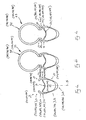
- Figure 4a shows the section of a rim 21 according to the invention that has an inverted A-shaped section.
- the radially inner body region is formed from a chamber 22, defined by a radially outer circumferential wall or upper bridge 23, by two side walls 24, 25 and by a radially inner circumferential wall or lower bridge 26.
- the side walls 24, 25 extend radially outwards to define circumferential wings 27, 28 for fitting a tyre 36.
- the circumferential wings 27, 28 have outer sides 29, 30 on which braking races 31, 32 are formed that provide braking surfaces on which the two brake pads (not shown) close during braking.
- the braking races 31, 32 are not parallel to one another, but rather converge: their distance apart (and the distance from the middle plane M of the rim 21) decreases as the distance from the centre of the rim 21 increases, starting substantially from the height of intersection with the upper bridge 23.
- a typical value of this narrowing is 0.15mm for each wing 27, 28, for a total of 0.3mm.
- the rim 21 is used to make a wheel 33, together with a hub connected to the rim 21 by spokes (the hub and the spokes are not shown in figures 4a to 4c , but are shown in figure 12 ) and to a tyre 36, mounted on the rim 21 between the wings 27, 28.
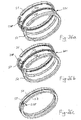
- the tyre 36 is mounted on the rim 21 ( figure 4b ) and then inflated ( figure 4c )
- the wings 27, 28 deform outwards, starting substantially from the intersection with the upper bridge 23, with a flaring effect.
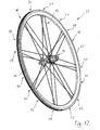
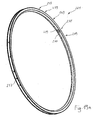
- Figures 11 and 12 show perspective views of the rim 21 and the wheel 33.
- the wheel 33 represented is a rear wheel, of the type with grouped spokes, and comprises the rim 21, a hub 34 and a set of spoke connections 35 between the hub 34 and the rim 21.
- the set of spoke connections 35 (also known as spoking) of the wheel 33 comprises twenty-four spokes 35 grouped in eight sets of three. There are therefore eight spoke attachment areas 41-48, each comprising three individual spoke attachment seats, alternating with eight intermediate areas 51-58.
- the rim 21 is made from composite material, for example made by moulding and cross linking or setting of a fibrous material, such a carbon fibre, in a matrix of polymeric material.
- a fibrous material such as a carbon fibre
- the details on the construction of the rim 21 in general can be found, for example, in EP 1 231 077 , incorporated here by reference.
- the rim 21 is in one piece, and therefore there is no jointing.
- a hole 37 is formed for housing a valve for retaining air inside the tyre 36 (not shown in figures 11 and 12 ) that can be associated with the outside of the rim 21.
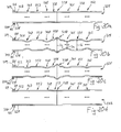
- the outer sides 29, 30 of the wings 27, 28 with the braking races 31, 32 are waved: indeed, at each spoke attachment area 41-48, the outer sides 29, 30 of the rim 21 are a shorter distance Da apart in the axial direction (with reference to the axis of the wheel 33) than their distance Di at the intermediate areas 51-58.
- the distance in the axial direction between the outer sides 29, 30 varies progressively between the spoke attachment areas 41-48 and the intermediate areas 51-58, as shown by figure 13a .
- the rim 21, and in particular the wings 27, 28 on whose outer sides 29, 30 the braking races 31, 32 are formed undergo a deformation (as already explained with reference to the prior art) such that the distance between the wings 27, 28 and more specifically between the outer sides 29, 30 at the spoke attachment areas 41-48 increases.
- the result is that the distance between the outer sides 29, 30 with the braking races 31, 32 of the rim 21 has lower variations with respect to the rim 21 without spokes (as shown in fig. 13b ).
- the rim 21 of figure 13a can be obtained, in general, according to what is described in the cited document EP 1 231 077 , by providing that the shape of the mould in the area for forming the wings has the desired waved shape.
- Figures 14 and 15 show perspective view of a rim 121 and a wheel 133 according to a different embodiment of the invention.
- the wheel 133 represented is again a rear wheel, of the type with grouped spokes, and comprises the rim 121, a hub 134 and a set of spoke connections 135 between the hub 134 and the rim 121.
- the rim 121 is of the metallic type, made through extrusion of a rod of suitable cross section, calendering it and jointing the ends at a jointing area 138. Therefore, figures 4a to 4c are also representative of the section of the rim 121 and of the wheel 133, in circumferential areas different to the jointing area 138. Such figures 4a to 4c therefore also display the reference numerals of the wheel 133 in brackets.
- a hole 137 is made to house a valve for retaining air inside the tyre 136 that can be associated with the outside of the rim 121.
- the jointing in the area 138 is carried out by butt welding of the ends of the extruded and calendered rod.
- a pair of full metallic inserts 139, 140 are inserted into the chamber 122 of the rim 121, used to allow the ends to be gripped with suitable pincers during welding without the risk of deforming the rim 121.
- the jointing in the area 138 can take place through a sleeve, inserted with interference and with a possible gluing substance in the inner chamber 122 of the rim 121.
- the joining in the area 138 can take place through pins inserted in the wall of the ends of the rim 121.
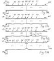
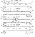
- Figure 16a schematically shows a blank of the rim 121 after extrusion, calendering, joining in the jointing area 138 and after the braking races 131, 132 have been formed (for example by turning) on the outer sides 129, 130 of the wings 127, 128.
- a deformation is carried out on such a preform of figure 16a (for example with one of the processes described hereafter) so that the outer sides 129, 130 of the wings 127, 128 of the rim 121 at the spoke attachment areas 141-148 are a shorter distance Da apart than the distance Di apart of the outer sides 129, 130 of the wings 127, 128 of the rim 121 at the intermediate areas 151-158 ( figure 16b ).
- the distance in the axial direction between the outer sides 129, 130 varies progressively between the spoke attachment areas 141-148 and the intermediate areas 151-158, as shown by figure 16b .
- the rim 121 When the wheel 133 is assembled using the rim 121 and the spokes 135 are tightened between the rim 121 and the hub 134, the rim 121, and in particular the outer sides 129, 130 of the wings 127, 128 on which the braking races 131, 132 are formed, undergo a deformation (as already explained with reference to the prior art) such that the distance between the outer sides 129, 130 at the spoke attachment areas 141-148 increases, without however reaching the distance at the intermediate areas 151-158.
- the result is that the distance between the outer sides 129, 130 with the braking races 131, 132 of the rim 121 has smaller variations than the rim 121 without spokes, as shown in figure 16c .
- the tyre 136 When, finally, the tyre 136 is mounted on the wheel 133 and inflated, there is a deformation of the wings 127, 128 outwards with a non-uniform increase in the distance between the outer sides 129, 130 with the braking races 131, 132 along the circumference: in the jointing area 138 the rigidity of the rim 121 is greater and the deformation occurs to a lower extent, whereas in the spoke attachment areas 141-148 the rigidity of the rim 121 is less and the deformation occurs to a greater extent. However, the greater deformation in the spoke attachment areas 141-142 is compensated by the residual inward deformation.
- Figures 17a-17c show a variant of the steps described in figures 16a-16c for making the same wheel 133, in which first the spokes 135 are tightened and then the deformation of the rim 121 is carried out.
- the spokes 135 are mounted and tightened on the preform ( figure 17a ).
- the tightening involves an outward deformation of the wings 127, 128 at the spoke attachment areas 141-148 ( figure 17b ).
- the inward deformation of the wings 127, 128 is carried out ( figure 17c ) at the spoke attachment areas 141-148 to obtain a shorter distance Da compared to the distance Di existing between the wings 127, 128 in the intermediate areas 151-158.
- the tyre 136 When, finally, the tyre 136 is mounted on the wheel 133 and inflated, there is an outward deformation of the wings 127, 128 with a non-uniform increase in the distance between the outer sides 129, 130 with the braking races 131, 132 along the circumference: in the jointing area 138 the rigidity of the rim 121 is greater and the deformation occurs to a lower extent, whereas in the spoke attachment areas 141-148 the rigidity of the rim 121 is less and the deformation occurs to a greater extent. However, the greater deformation in the spoke attachment areas 141-142 is compensated by the residual inward deformation.
- the rim 121 shall have the same shape obtained with the previous process before the assembly of the spokes 135, i.e. that of figure 16b .
- Figures 19a and 19b show perspective views of a rim 221 and a wheel 233 according to a different embodiment of the invention.
- the wheel 233 represented is a front wheel, of the type with equally distributed single spokes, and comprises the rim 221, a hub 234 and a set of spoke connections 235 between the hub 234 and spoke attachment areas 249 on the rim 221, alternating with intermediate areas 259.
- the rim 221 is of the metallic type, made through extrusion of a rod having a suitable cross section, calendering it and joining the ends at a jointing area 238. Therefore, figures 4a to 4c are also representative of the section of the rim 221 and of the wheel 233, in circumferential areas different to the jointing area 238. Such figures 4a to 4c thus also display the reference numerals of the wheel 233, in brackets.
- a hole 237 is made in the rim 221 to house a valve for retaining air inside the tyre 236 that can be associated with the outside of the rim 221.
- the jointing in the area 238 is carried out by butt welding of the ends of the extruded and calendered rod.
- a pair of full metallic inserts 239, 240 (summarily shown in figure 19a ) are inserted into the chamber 222 of the rim 221, used to allow the ends to be gripped with suitable pincers during welding without the risk of deforming the rim 221.
- Figures 18a to 18c refer to the rim 221 and to the wheel 233 .
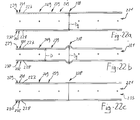
- Figure 18a schematically shows a blank of the rim 221 after extrusion, calendering, joining in the jointing area 238 and after the braking races 231, 232 have been formed (for example by turning) on the outer sides 229, 230 of the wings 227, 228.
- a deformation is made on the preform of figure 18a (for example with one of the processes described hereafter) so that, in the rim 221, the outer sides 229, 230 of the wings 227, 228 with the braking races 231, 232, are a greater distance Dg apart at the jointing area 238 than the distance D of the outer sides 229, 230 in the other areas (widening of the jointing area 238, figure 18b ).
- the distance in the axial direction between the outer sides 229, 230 varies progressively between the jointing area 238 and the adjacent areas, as shown by figure 18b .
- Figures 20a to 20d refer to a rim 321 and to a wheel 333 similar to the rim 121 and wheel 133 described above; in particular, the rim 221 is of the metallic type with a jointing area 338 and the wheel 333 has the same distribution of the spokes as the type described above.
- figures 14 and 15 are also representative of the rim 321 and of the wheel 333. Such figures thus also display the reference numerals of the wheel 333, in brackets.
- figures 4a to 4c are also representative of the section of the rim 321 and of the wheel 333, in circumferential areas different to the jointing area 338. Such figures 4a to 4c thus also display the reference numerals of the wheel 333 in brackets.
- a first deformation is made on the preform of figure 20a (for example with one of the processes described hereafter) so that, in the rim 321, the outer sides 329, 330 of the wings 327, 328 with the braking races 331, 332, are a shorter distance Da apart at the spoke attachment areas 341-348 than the distance Di of the outer sides 329, 330 with the braking races 331, 332 of the rim 321 at the intermediate areas 351-358.
- a second deformation is then made so that the outer sides 329, 330 of the wings 327, 328 of the rim 321 are a greater distance Dg apart at the jointing area 338 than the distance Di of the outer sides 329, 330 in the adjacent areas.
- the distance in the axial direction between the outer sides 329, 330 varies progressively between the jointing area 338 and the adjacent areas and between the spoke attachment areas 341-348 and the intermediate areas 351-358, as shown by figure 20b .
- the tyre 336 When, finally, the tyre 336 is mounted on the wheel 333 and inflated, there is an outward deformation of the wings 327, 328 with a non-uniform increase in the distance between the outer sides 329, 330 with the braking races 331, 332 along the circumference: in the jointing area 338 the rigidity of the rim 321 is greater and the deformation occurs to a lower extent, whereas in the spoke attachment areas 341-348 the rigidity of the rim 321 is less and the deformation occurs to a greater extent. However, the reduced deformation in the jointing area 338 is compensated by the previous outward deformation, as well as the greater deformation in the spoke attachment areas 341-348 is compensated by the residual inward deformation. In the wheel 333 with the tyre 336 inflated, therefore, the localised waving effect in the jointing area 338 due to the joint and the distributed waving effect are reduced and, at best, are inexistent (as shown in figure 20d ).
- the distance between the outer sides 329, 330 of the wings 327, 328 with the braking races 331, 332 has smaller variations, and at best no variation, along the entire circumference of the wheel 333, including the jointing area 338.
- Figures 21a-21d show a variant of the steps described in figures 20a-20d for making the same wheel 333, in which first the spokes 335 are tightened and then the rim 321 is deformed.
- the spokes 335 are mounted on the preform ( figure 21 a) and tightened.
- the tightening involves an outward deformation of the wings 327, 328 at the spoke attachment areas 341-348 ( figure 21 b) .
- a first deformation is carried out to deform the wings 327, 328 inwards at the spoke attachment areas 341-348 to obtain a shorter distance Da than the distance Di existing between the wings 327, 328 in the intermediate areas 351-358.
- the tyre 336 When, finally, the tyre 336 is mounted on the wheel 333 and inflated, there is an outward deformation of the wings 327, 328 with a non-uniform increase in the distance between the outer sides 329, 330 with the braking races 331, 332 along the circumference: in the jointing area 338 the rigidity of the rim 321 is greater and the deformation occurs to a lower extent, whereas in the spoke attachment areas 341-348 the rigidity of the rim 321 is less and the deformation occurs to a greater extent. However, the lower deformation is compensated by the previous outward deformation, just as the greater deformation in the spoke attachment areas 341-348 is compensated by the residual inward deformation. In the wheel 333 with the tyre 336 inflated, therefore, the localised waving effect due to the jointing 338 is reduced and, at best, is inexistent ( figure 21 d) .
- the distance between the outer sides 329, 330 of the wings 327, 328 with the braking races 331, 332 has smaller variations, and at best no variation, along the entire circumference of the wheel 333, including the jointing area 338.
- the rim 321 shall have the same shape obtained with the previous process before the assembly of the spokes 335, i.e. that of figure 20b .
- a deformation is carried out on such a preform of figure 22a (for example with one of the processes described hereafter, in particular the one illustrated in figures 26a to 26d ) so that, in the rim 221, the outer sides 229, 230 of the wings 227, 228 with the braking races 231, 232 of the rim 221 are a greater distance Dg apart at the jointing area 238 than the distance D of the outer sides 229, 230 in the other areas (similarly to what has been seen for figures 18a-18c ).
- a rim like the rims shown and described above can be made in various ways so as to compensate the flaring effect.
- the shape of the rim ( figures 3a and 4a ) with the wings converging is achieved directly in the moulding step of the rim (for example using the process described in EP 1 231 077 and modifying the shape of the mould in accordance with the profile to be obtained).
- rims made from metal and as shown in figures 5a-5c and 6a-6c it can be provided to start from an extruded piece with the wings of suitable section (increased), then machining the outer sides of the wings along the entire circumference (turning) so that they have the desired inclination.
- Another alternative is to provide a standard extruded piece (for example the one shown in figure 2a ) that is then inserted inside two suitably shaped half-moulds S1 and S2, as schematically indicated in figures 7a to 7d ; the closing of the half-moulds S1 and S2 determines the deformation of the wings along the entire circumference and therefore the desired shape of figure 7e (that corresponds to the rim of figure 4a ).
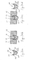
- the wing 228 is gripped between the ends of the arms P1 and P2 of a pincer P ( figure 23b ).
- the pincer P is rotated ( figure 23c ) in a controlled manner so that the wing 228 is deformed by a predetermined amount (for example 0.1mm).
- the operation is repeated in an analogous way for the other wing 227.
- the final effect shall be a widening of the wings 227, 228, and therefore an increase in distance between the outer sides 229, 230, by 0.2mm ( figure 23d ).
- the deformation of the wings can be carried out inwards.
- the rim 221 is inserted in two half-moulds S1 and S2.
- two punches S3 and S4 are inserted ( figure 24b ) that push the wings 227, 228 against the respective shaped walls of the half-moulds S1 and S2 ( figure 24c ).
- a presser element PR in the form of a tapered toroidal slug ( figure 25e ) is pushed radially from the outside towards the centre of the rim 221 ( figure 25c ) to deform the wings 227, 228 outwards.
- an element of thickness SP is inserted to keep the jointing area 238 at the distance Dg ( figure 19b ).
- the rim 221 is then inserted into two half-moulds S1, S2 that push the wings 227, 228 to the distance apart D for the entire circumference, except for the jointing area 238 where the element of thickness SP is located.
- each of the compensations of the flaring, distributed waving and localised waving effects can be implemented alone or with one or more of the others on the same rim.
- the compensation of the flaring effect has been illustrated, but there could also be a compensation of the distributed waving effect and/or (if the rim 1 is metallic) of the localised waving effect.
- the compensation of the distributed waving effect has been illustrated, but not of the localised waving effect and of the flaring effect, which are still present since the rim 121 is made from metal, with jointing.
- the compensation of the localised waving effect has been illustrated, but not of the distributed waving effect and of the flaring effect, which are still present since the rim 221 is made from metal, with jointing.
- the compensation both of the distributed waving effect and of the localised waving effect have been illustrated.
Landscapes
- Engineering & Computer Science (AREA)
- Mechanical Engineering (AREA)
- Chemical & Material Sciences (AREA)
- Materials Engineering (AREA)
- Tires In General (AREA)
- Axle Suspensions And Sidecars For Cycles (AREA)
Applications Claiming Priority (1)
| Application Number | Priority Date | Filing Date | Title |
|---|---|---|---|
| IT000917A ITMI20070917A1 (it) | 2007-05-07 | 2007-05-07 | Cerchio e ruota di bicicletta con alette a svasatura compensata |
Publications (1)
| Publication Number | Publication Date |
|---|---|
| EP1990214A1 true EP1990214A1 (de) | 2008-11-12 |
Family
ID=38544187
Family Applications (1)
| Application Number | Title | Priority Date | Filing Date |
|---|---|---|---|
| EP08005649A Withdrawn EP1990214A1 (de) | 2007-05-07 | 2008-03-26 | Felge und Fahrrad mit Flügeln mit Schleifausgleich |
Country Status (5)
| Country | Link |
|---|---|
| US (1) | US20080315677A1 (de) |
| EP (1) | EP1990214A1 (de) |
| JP (1) | JP2008285148A (de) |
| CN (1) | CN101311005A (de) |
| IT (1) | ITMI20070917A1 (de) |
Families Citing this family (4)
| Publication number | Priority date | Publication date | Assignee | Title |
|---|---|---|---|---|
| ITMI20070916A1 (it) * | 2007-05-07 | 2008-11-08 | Campagnolo Srl | Cerchio e ruota di bicicletta con alette ad ondulazione localizzata compensata |
| ITMI20070915A1 (it) * | 2007-05-07 | 2008-11-08 | Campagnolo Srl | Cerchio e ruota di bicicletta con alette a ondulazione compensata |
| US20140132060A1 (en) * | 2012-11-15 | 2014-05-15 | Alex Global Technology, Inc. | Bicycle Wheel Rim |
| DE102021006134A1 (de) * | 2021-12-13 | 2023-06-15 | Dt Swiss Ag | Verfahren zur Herstellung elner Felge, Felge und Werkzeugeinrichtung |
Citations (7)
| Publication number | Priority date | Publication date | Assignee | Title |
|---|---|---|---|---|
| GB523958A (en) * | 1939-01-17 | 1940-07-26 | Roadless Traction Ltd | Cleats or grips for wheels of tractors and other vehicles |
| DE4200227A1 (de) * | 1992-01-08 | 1993-07-15 | Btg Bike Tech Saak & Kellner E | Felge fuer fahrraeder und aehnliche fahrzeuge |
| US5603553A (en) * | 1991-12-07 | 1997-02-18 | F. W. Brokelmann Aluminiumwerk Gmbh & Co. | Bicycle wheel with disk cover |
| EP0936085A2 (de) * | 1998-02-10 | 1999-08-18 | Campagnolo S.R.L. | Radfelge, insbesondere für ein Hinterrad eines Fahrads |
| US6024413A (en) * | 1997-09-04 | 2000-02-15 | Spencer Technology, Inc. | Bicycle wheel and rim |
| EP1231077A2 (de) | 2001-02-13 | 2002-08-14 | Campagnolo S.R.L. | Herstellungsverfahren einer Fahrradfelge, Vorichtung zur Durchführung dieses Verfahrens, und auf diese Weise erhaltene Felge für ein Fahrradrad |
| FR2890580A1 (fr) * | 2005-09-14 | 2007-03-16 | Salomon Sa | Jante pour roue a rayons et leur procede de fabrication |
Family Cites Families (12)
| Publication number | Priority date | Publication date | Assignee | Title |
|---|---|---|---|---|
| US1563811A (en) * | 1925-12-01 | Rim for tires and method of making the same | ||
| US1942091A (en) * | 1932-07-30 | 1934-01-02 | Budd Wheel Co | Manufacture of wire wheels |
| US2126223A (en) * | 1937-12-22 | 1938-08-09 | Frank W Schwinn | Metal wheel rim |
| US5228756A (en) * | 1990-07-25 | 1993-07-20 | Jiri Krampera | Rim for a spoked bicycle rear wheel |
| US5499864A (en) * | 1993-06-16 | 1996-03-19 | Klein Bicycle Corporation | Bicycle wheel rims |
| US5734142A (en) * | 1996-07-19 | 1998-03-31 | Trek Bicycle Corporation | Method of welding electrically conductive metal profiles |
| ATE505340T1 (de) * | 2001-11-29 | 2011-04-15 | Compositech Inc | Verbundfahrradfelge mit nahtloser bremsfläche |
| TW549249U (en) * | 2002-10-16 | 2003-08-21 | Alex Global Technology Inc | Wheel rim for bicycle with protruded corner strengthening structure |
| US6961999B2 (en) * | 2003-02-25 | 2005-11-08 | William B Shook | Lightweight bicycle wheel rim and method for producing it |
| DE102006010445B4 (de) * | 2006-03-03 | 2014-02-13 | Denk Engineering Gmbh | Felge |
| ITMI20070916A1 (it) * | 2007-05-07 | 2008-11-08 | Campagnolo Srl | Cerchio e ruota di bicicletta con alette ad ondulazione localizzata compensata |
| ITMI20070915A1 (it) * | 2007-05-07 | 2008-11-08 | Campagnolo Srl | Cerchio e ruota di bicicletta con alette a ondulazione compensata |
-
2007
- 2007-05-07 IT IT000917A patent/ITMI20070917A1/it unknown
-
2008
- 2008-03-26 EP EP08005649A patent/EP1990214A1/de not_active Withdrawn
- 2008-05-02 JP JP2008120439A patent/JP2008285148A/ja active Pending
- 2008-05-07 CN CNA2008100887965A patent/CN101311005A/zh active Pending
- 2008-05-07 US US12/116,577 patent/US20080315677A1/en not_active Abandoned
Patent Citations (7)
| Publication number | Priority date | Publication date | Assignee | Title |
|---|---|---|---|---|
| GB523958A (en) * | 1939-01-17 | 1940-07-26 | Roadless Traction Ltd | Cleats or grips for wheels of tractors and other vehicles |
| US5603553A (en) * | 1991-12-07 | 1997-02-18 | F. W. Brokelmann Aluminiumwerk Gmbh & Co. | Bicycle wheel with disk cover |
| DE4200227A1 (de) * | 1992-01-08 | 1993-07-15 | Btg Bike Tech Saak & Kellner E | Felge fuer fahrraeder und aehnliche fahrzeuge |
| US6024413A (en) * | 1997-09-04 | 2000-02-15 | Spencer Technology, Inc. | Bicycle wheel and rim |
| EP0936085A2 (de) * | 1998-02-10 | 1999-08-18 | Campagnolo S.R.L. | Radfelge, insbesondere für ein Hinterrad eines Fahrads |
| EP1231077A2 (de) | 2001-02-13 | 2002-08-14 | Campagnolo S.R.L. | Herstellungsverfahren einer Fahrradfelge, Vorichtung zur Durchführung dieses Verfahrens, und auf diese Weise erhaltene Felge für ein Fahrradrad |
| FR2890580A1 (fr) * | 2005-09-14 | 2007-03-16 | Salomon Sa | Jante pour roue a rayons et leur procede de fabrication |
Also Published As
| Publication number | Publication date |
|---|---|
| US20080315677A1 (en) | 2008-12-25 |
| JP2008285148A (ja) | 2008-11-27 |
| CN101311005A (zh) | 2008-11-26 |
| ITMI20070917A1 (it) | 2008-11-08 |
Similar Documents
| Publication | Publication Date | Title |
|---|---|---|
| EP1990215A1 (de) | Felge und Fahrrad mit Flügeln mit begrenztem Schlingerausgleich | |
| US6425641B1 (en) | Spoked cycle wheel | |
| EP1990216A1 (de) | Felge und Fahrrad mit Flügeln mit Schlingerausgleich | |
| EP2674304B1 (de) | Fahrradrad und zugehöriges Herstellungsverfahren | |
| EP3505365B1 (de) | Fahrradfelge | |
| US6402256B1 (en) | Bicycle rim and wheel having such a rim | |
| TWI398367B (zh) | 用於自行車輻條輪之輪圈、車輪以及其製造方法 | |
| US20080054712A1 (en) | Rim for a spoked bicycle wheel and relative spoked wheel | |
| US20080315674A1 (en) | Spoked bicycle wheel, components thereof and relative manufacturing methods | |
| JP3711346B2 (ja) | 自転車用リム | |
| JP2008087757A (ja) | 自転車のスポーク付き車輪用リム、その製造方法、およびスポーク付き車輪 | |
| US7331639B2 (en) | Bicycle rim | |
| US20080315677A1 (en) | Rim and bicycle wheel with wings with compensated flaring | |
| US10252568B2 (en) | Bicycle wheel and relative manufacturing process | |
| JP2004359217A (ja) | 自転車用リム | |
| TWI627077B (zh) | 自行車輪圈和相應的自行車車輪 | |
| EP1759878B1 (de) | Speichenrad für Fahrräder, korrespondierende Speichenverbindungen, und korrespondierendes Verfahren |
Legal Events
| Date | Code | Title | Description |
|---|---|---|---|
| PUAI | Public reference made under article 153(3) epc to a published international application that has entered the european phase |
Free format text: ORIGINAL CODE: 0009012 |
|
| AK | Designated contracting states |
Kind code of ref document: A1 Designated state(s): AT BE BG CH CY CZ DE DK EE ES FI FR GB GR HR HU IE IS IT LI LT LU LV MC MT NL NO PL PT RO SE SI SK TR |
|
| AX | Request for extension of the european patent |
Extension state: AL BA MK RS |
|
| 17P | Request for examination filed |
Effective date: 20090430 |
|
| 17Q | First examination report despatched |
Effective date: 20090602 |
|
| AKX | Designation fees paid |
Designated state(s): AT BE BG CH CY CZ DE DK EE ES FI FR GB GR HR HU IE IS IT LI LT LU LV MC MT NL NO PL PT RO SE SI SK TR |
|
| STAA | Information on the status of an ep patent application or granted ep patent |
Free format text: STATUS: THE APPLICATION IS DEEMED TO BE WITHDRAWN |
|
| 18D | Application deemed to be withdrawn |
Effective date: 20091013 |