EP1990246A1 - Airbag comprenant une buse souple pour l'alimentation en gaz - Google Patents
Airbag comprenant une buse souple pour l'alimentation en gaz Download PDFInfo
- Publication number
- EP1990246A1 EP1990246A1 EP07009416A EP07009416A EP1990246A1 EP 1990246 A1 EP1990246 A1 EP 1990246A1 EP 07009416 A EP07009416 A EP 07009416A EP 07009416 A EP07009416 A EP 07009416A EP 1990246 A1 EP1990246 A1 EP 1990246A1
- Authority
- EP
- European Patent Office
- Prior art keywords
- gas
- arrangement according
- airbag arrangement
- section
- gas generator
- Prior art date
- Legal status (The legal status is an assumption and is not a legal conclusion. Google has not performed a legal analysis and makes no representation as to the accuracy of the status listed.)
- Withdrawn
Links
- 239000000463 material Substances 0.000 claims description 10
- 150000001875 compounds Chemical class 0.000 claims description 8
- 238000004026 adhesive bonding Methods 0.000 claims description 4
- 238000009958 sewing Methods 0.000 claims description 4
- 239000004753 textile Substances 0.000 claims description 4
- 239000004033 plastic Substances 0.000 claims description 3
- 238000003466 welding Methods 0.000 claims description 3
- 210000004712 air sac Anatomy 0.000 claims description 2
- 230000007935 neutral effect Effects 0.000 claims description 2
- 238000007664 blowing Methods 0.000 abstract description 2
- 239000007789 gas Substances 0.000 description 223
- 238000009826 distribution Methods 0.000 description 5
- 238000004519 manufacturing process Methods 0.000 description 4
- 238000009434 installation Methods 0.000 description 3
- 239000003380 propellant Substances 0.000 description 3
- 238000007789 sealing Methods 0.000 description 3
- 239000000853 adhesive Substances 0.000 description 2
- 230000001070 adhesive effect Effects 0.000 description 2
- 238000005520 cutting process Methods 0.000 description 2
- 239000004744 fabric Substances 0.000 description 2
- 230000007704 transition Effects 0.000 description 2
- 238000004891 communication Methods 0.000 description 1
- 230000001419 dependent effect Effects 0.000 description 1
- 230000001627 detrimental effect Effects 0.000 description 1
- 238000011161 development Methods 0.000 description 1
- 230000018109 developmental process Effects 0.000 description 1
- 230000000694 effects Effects 0.000 description 1
- 238000005516 engineering process Methods 0.000 description 1
- 230000012447 hatching Effects 0.000 description 1
- 239000001307 helium Substances 0.000 description 1
- 229910052734 helium Inorganic materials 0.000 description 1
- SWQJXJOGLNCZEY-UHFFFAOYSA-N helium atom Chemical compound [He] SWQJXJOGLNCZEY-UHFFFAOYSA-N 0.000 description 1
- 239000002184 metal Substances 0.000 description 1
Images


Classifications
-
- B—PERFORMING OPERATIONS; TRANSPORTING
- B60—VEHICLES IN GENERAL
- B60R—VEHICLES, VEHICLE FITTINGS, OR VEHICLE PARTS, NOT OTHERWISE PROVIDED FOR
- B60R21/00—Arrangements or fittings on vehicles for protecting or preventing injuries to occupants or pedestrians in case of accidents or other traffic risks
- B60R21/02—Occupant safety arrangements or fittings, e.g. crash pads
- B60R21/16—Inflatable occupant restraints or confinements designed to inflate upon impact or impending impact, e.g. air bags
- B60R21/26—Inflatable occupant restraints or confinements designed to inflate upon impact or impending impact, e.g. air bags characterised by the inflation fluid source or means to control inflation fluid flow
- B60R21/261—Inflatable occupant restraints or confinements designed to inflate upon impact or impending impact, e.g. air bags characterised by the inflation fluid source or means to control inflation fluid flow with means other than bag structure to diffuse or guide inflation fluid
-
- B—PERFORMING OPERATIONS; TRANSPORTING
- B60—VEHICLES IN GENERAL
- B60R—VEHICLES, VEHICLE FITTINGS, OR VEHICLE PARTS, NOT OTHERWISE PROVIDED FOR
- B60R21/00—Arrangements or fittings on vehicles for protecting or preventing injuries to occupants or pedestrians in case of accidents or other traffic risks
- B60R21/02—Occupant safety arrangements or fittings, e.g. crash pads
- B60R21/16—Inflatable occupant restraints or confinements designed to inflate upon impact or impending impact, e.g. air bags
- B60R21/26—Inflatable occupant restraints or confinements designed to inflate upon impact or impending impact, e.g. air bags characterised by the inflation fluid source or means to control inflation fluid flow
- B60R21/261—Inflatable occupant restraints or confinements designed to inflate upon impact or impending impact, e.g. air bags characterised by the inflation fluid source or means to control inflation fluid flow with means other than bag structure to diffuse or guide inflation fluid
- B60R2021/2612—Gas guiding means, e.g. ducts
-
- B—PERFORMING OPERATIONS; TRANSPORTING
- B60—VEHICLES IN GENERAL
- B60R—VEHICLES, VEHICLE FITTINGS, OR VEHICLE PARTS, NOT OTHERWISE PROVIDED FOR
- B60R21/00—Arrangements or fittings on vehicles for protecting or preventing injuries to occupants or pedestrians in case of accidents or other traffic risks
- B60R21/02—Occupant safety arrangements or fittings, e.g. crash pads
- B60R21/16—Inflatable occupant restraints or confinements designed to inflate upon impact or impending impact, e.g. air bags
- B60R21/26—Inflatable occupant restraints or confinements designed to inflate upon impact or impending impact, e.g. air bags characterised by the inflation fluid source or means to control inflation fluid flow
- B60R21/261—Inflatable occupant restraints or confinements designed to inflate upon impact or impending impact, e.g. air bags characterised by the inflation fluid source or means to control inflation fluid flow with means other than bag structure to diffuse or guide inflation fluid
- B60R2021/2612—Gas guiding means, e.g. ducts
- B60R2021/2615—Gas guiding means, e.g. ducts for diverting the gas into a plurality of bags
Definitions
- the invention relates to an airbag arrangement for motor vehicles with at least one inflatable airbag and with a gas line to which the airbag is connected and over which the airbag is inflated by means of a mounted in the vehicle state remote from the airbag inflator.
- Such airbag arrangements are of particular interest if the gas generator can not or should not be arranged in the immediate vicinity of the airbag.
- the gas line provided between the gas generator and the airbag results, in principle, in a greater flexibility in the design and installation of the airbag arrangement in the vehicle.
- the object of the invention is to develop an airbag assembly of the type mentioned in such a way that they wall at the lowest possible cost and low cost in manufacturing versatile and space-saving in the vehicle can be mounted.
- a gas-tight connection is provided between the gas line and at least one further component of the airbag arrangement, which may be the airbag, a connection piece or a further gas line piece, formed by a connecting section of the gas line and a connecting section of the further component becomes.
- the connecting sections are each such, in particular flexible, flexible and / or soft, that under the influence of gas released by the gas generator, they can pass from a flat mounting configuration into an inflated configuration with an enlarged flow cross section relative to the mounting configuration.
- Such a flexible, flexible and / or soft connection requires extremely little space in the assembled state due to its then flat and thus to some extent two-dimensional configuration. If necessary, the required flow cross-section for the gas by the action of the gas generator results in a sense automatically by the gas generator transfers the connection from the flat mounting configuration in the Aufblaskonfiguration, in particular inflates, unfolds, pushes or expands, which according to the invention by the flexible, flexible and / or soft configuration of the connecting sections is made possible.
- the compound of the invention is universally applicable insofar as it can be used between different components of the airbag assembly.
- both the connection between the gas line and the airbag itself and the connection between the gas line and a further gas line piece or a connecting piece can be designed in a flexible way according to the invention.
- connection piece is a component which is used in the region of the connection of the gas generator to the gas line and, in particular, serves to produce the gas-tightness between gas generator and gas line in this area.
- further gas line pieces which are connected in accordance with the invention with the leading to the air bag gas line, can be realized in principle any branched gas line systems in which the gas-tight connections of the individual components with each other due to the flexible, flexible and / or soft design particularly Space-saving in the vehicle can be accommodated.
- the compound of the invention can be used in connection with a gas distribution, which can be used in particular in applications where two air bags are inflated simultaneously with a gas generator or - generally expressed - the number of available gas sources is smaller than that Number of airbags to be arranged separately in the vehicle.
- a gas distributor according to the invention in particular making use of the compound according to the invention, can be connected to a single gas outlet of a gas generator and used simultaneously to supply the gas released from the gas generator two air bags arranged spatially separate from one another, around the air bags at the same time inflate. It was found that even with not exactly symmetrical design of the gas line system, the released gas from the gas generator can be distributed substantially uniformly on the two air bags. In particular, no disturbing effects occur in such a way that the released from the gas generator gas flows predominantly to only one of the two air bags, which would lead to an unacceptable in practice uneven inflation of the two air bags. This can probably be attributed to the high dynamics of the release of a gas generator released gas flow.
- independent protection is claimed for an airbag assembly having at least two airbag mounted sacks disposed apart from the vehicle and at least one inflator for simultaneously inflating the airbags, wherein the airbags are connected to a common gas outlet of the inflator.
- the gas generator comprises a, designed in particular as a diffuser, distributor section, via which the gas can flow simultaneously in at least two different, in particular opposite directions, wherein the distributor section of the gas generator is arranged in a gas line system to which the both gas bags are connected, wherein the gas line system is such, in particular flexible, flexible and / or soft, is formed, that under the influence of gas released by the gas generator from a flat mounting configuration can get into an inflated configuration with respect to the mounting configuration enlarged flow cross-section.
- the distributor section of the gas generator is arranged in a, in particular continuous and / or one-piece, gas line which connects the two air bags together.
- a gas line system for a motor vehicle airbag arrangement which has at least two outputs, to which two airbags arranged remote from one another in the vehicle-mounted state can be connected, and at least one input, is claimed independently.
- the gas distributor is such, in particular flexible, flexible and / or soft, is formed that he under the influence of gas released by the gas generator from a flat mounting configuration in a Friedblaskonfiguration with respect to Mounting configuration can reach enlarged flow cross-section.
- the gas distributor comprises a, designed in particular as a diffuser, distributor portion which is connected to a gas outlet of the gas generator or connected to a gas outlet of the gas generator and simultaneously released via the gas released from the gas generator in at least two different, in particular opposite , Directions can flow.
- the gas distributor comprises a continuous gas line, with which the two air bags are connectable to each other, wherein the distributor section of the gas generator is arranged in the gas line.
- At least one connecting portion is formed by a flexible, flexible and / or soft tubular or hose-like structure and in particular by a hose.
- the gas line, the connecting piece and the further gas line piece are each formed essentially as a whole by a hose.
- the connecting sections or the gas guide tubes can be made of a woven or textile material.
- the material or a similar material is used from which the shell of the airbag is made or can be made.
- connection is formed exclusively by the flexible, flexible and / or soft connection sections.
- additional rigid or rigid elements e.g. to stabilize the connection or to deflect the gas flowing from the gas generator.
- the entire gas line system in the context of the invention consists of flexible, flexible and / or soft in particular hose-like gas lines.
- a particularly simple and inexpensive to produce distribution of the gas provided by a single gas generator to two in the assembled state spatially remote airbags can be realized according to a further embodiment of the invention, characterized in that the two air bags by means of a continuous gas line connected to each other and the connection of the gas generator takes place at an intermediate portion of the gas line. This intermediate section is then part of a flexible connection or flexible gas distributor according to the invention.
- the gas generator is preferably a gas-neutral gas generator.
- the thrust neutrality of the gas generator can be used in a skilful manner for a gas distribution to two spatially separate air bags by a trained especially as a diffuser manifold section of the gas generator over which the gas can flow simultaneously in at least two different, in particular opposite directions, in the flexible gas distributor according to the invention and in particular in a continuous, the two air bags interconnecting gas line is integrated.
- the distributor section can be arranged in a gas line which connects the two spatially separate air bags with one another, such that the opposing gas flow directions of the distributor section are at least substantially aligned with the longitudinal axis of the gas line, at least in the region of the connection of the gas generator to the gas line ,
- the distributor section of the gas generator and the continuous gas line then together form a gas distributor for simultaneous inflation of the two air bags.
- a continuous gas line in this context has the advantage that when inflating the air bags, the forces acting on the gas line by the flowing gas, are opposite to each other and thus cancel each other.
- a somewhat push-neutral connection of a gas generator to a gas line system or to a distribution line or a somewhat thrust-neutral gas distributor can be realized in the simplest possible way.
- a particularly space-saving arrangement is obtained according to a further embodiment of the invention, when a distributor portion of the gas generator is deformable in such a way that the distributor portion under the influence of gas released by the gas generator from a flat mounting configuration in a Aufblaskonfiguration enlarged with respect to the mounting configuration Flow cross section can get.
- the dynamics of the gas leaving the gas generator can be exploited in order to push apart or "unfold" a piece of pipe which is flat or compressed during assembly for assembly purposes and which forms part of the distributor section.
- connection between the individual components in particular between the gas line on the one hand and the air bag, the connecting piece or the other gas line piece on the other hand, can be designed in particular in the manner of a plug / slot connection.
- the one component is provided in its sheath or wall with a slot or notch, which cooperates with an end portion of the other component, wherein the end portion provided with an open front end end portion is understood in the Aufblaskonfiguration a tubular or tubular shape having connecting portion.
- the end portion can be inserted, for example, in the slot of the other component.
- the end section is provided with at least one and in particular with two opposite lateral openings, in particular in the form of slots or notches, which preferably extend from the open end of the end section.
- the end portion is effectively provided with tabs distributed in the circumferential direction which, due to the flexibility, move relative to one another and thus can be used to secure the end portion to the shell or wall of the other connection portion, for example by sewing, gluing or welding.
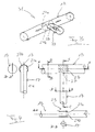
- Fig. 1 to 4 illustrate the invention using the example of a flexible gas distributor 31, which makes use of the inventive connection between two flexible connecting portions 23, 27 of two components of an air bag assembly for motor vehicles.
- the one component is a gas pipe 13, which is shown only partially, for example in the form of a fabric or textile hose, wherein the gas pipe 13 can also be formed by a hose or a tube made of a sufficiently flexible, flexible or soft plastic material.
- the other component 17 is also a fabric, textile or plastic tube whose diameter can correspond to that of the gas line 13 or deviate from it.
- the component 17 is also referred to below as a connection piece, since it for the gas-tightness of the gas distributor 31 according to the invention in the area the connection of a gas generator 15 (see. Fig. 5 ) to the gas line 13, which will be discussed in more detail below.
- the envelope or wall of the gas line 13 is provided with a slot-shaped opening 25, in particular made by cutting, which extends parallel to a longitudinal axis of the gas line 13 here, whereby an oblique or vertical course of the slot 25 is possible.
- a connecting section serving as an end portion 27 of the connector 17 is inserted into the slot 25 in the embodiment shown here, which the in Fig. 2 has shown arrangement.
- the length of the slot 25 is in accordance with the width of the fitting 17 in the flat, compressed mounting state Fig. 1 Voted.
- the end portion 27 is provided with two opposite, starting from the open end of the end portion 27 lateral cuts 29.
- two flap-like or tab-like wall regions 27a, 27b are formed.
- the length of the cuts, slots or openings 29 of the end portion 27, which here parallel to the longitudinal axis of the connecting piece 17, but also an oblique or vertical course is possible, is based on the width of the line section 13 in the flat mounting state Fig. 1 Voted.
- the slots can be made by cutting the material or by removing material.
- the tabs 27a, 27b are used to attach the end portion 27 on the connecting portion 23 of the gas line 13.
- the attachment is done for example by gluing, sewing or wear.
- adhesive surfaces or the adhesive used are indicated by hatching.
- the tabs 27a, 27b of the connecting piece 17 are glued with their outer side to the inner wall of the gas line 13 in the region of the connecting portion 23, for example.
- the compound formed in this way or the gas distributor 31 formed thereby extends in the assembly configuration according to FIG Fig. 1 and 2 practically exclusively in one level. Due to the flat configuration of the gas distributor can be extremely space-saving installed in a vehicle and integrated eg in the vehicle roof.
- the gas distributor 31 flows through gas released by means of the gas generator 15, it automatically passes into the inflation configuration according to FIG 3 and 4 in that the connecting piece 17 and the gas line 13 assume a tubular configuration which, with a sufficient flow cross-section, enables the gas to be transported to a respective destination.
- the internal arrangement of the fastening tabs 27a, 27b has the advantage that gas flowing in via the connecting piece 17 into the gas line 13 on the inner wall is not exposed to any obstacles which are disadvantageous in terms of flow technology.
- the gas line 13 it is also possible to surround the gas line 13 with the two fastening tabs 27 a, 27 b outside and the tabs 27 a, 27 b on the side facing away from the connector 17 side of the gas line 13, for example, by gluing, sewing or welding together. Also in this way can be a secure mechanical hold of the connector 17 on the gas line 13 as well as an optimal in terms of flow and with respect to the environment gas-tight communication between the connector 17 and the connection opening 25 of the gas line 13 achieve.
- Fig. 5 shows the gas distributor 31 according to the invention together with two schematically indicated air bags 11 and a gas generator 15, which serves to inflate the two air bags 11, if necessary, at the same time.
- the continuous flexible hose forming the gas line 13 connects the two airbags 11 to each other.
- the two ends of the gas pipe 13 each connected to an air bag 11 respectively form an end portion as mentioned above in connection with the fitting 17, while a slit-shaped opening corresponding to the above-mentioned opening 25 is formed in the air bag 11, respectively to accommodate the relevant end portion of the gas line 13.
- a further advantage of the compound according to the invention results. It is possible in a particularly simple manner to influence the blowing or inflating behavior of the airbag 11 in that one or more parameters of the plug / slot connection are varied. For example, it can be set how deep the end section of the gas line 13 projects into the airbag 11. Furthermore, the angle at which the gas line 13 in the region of its associated with the air bag 11 Endes relative to the airbag 11 extends to be adapted to the particular circumstances. The point within the airbag 11, at which the gas exits the end of the gas line 13, can be positioned virtually anywhere within the airbag 11. Furthermore, it is possible to design the end of the gas line 13 located in the airbag 11 differently with respect to the escape of the gas. For example, the end of the gas line 13 may be closed at the end and be provided laterally with one or more, for example, slot-shaped, gas outlet openings. This results in a wide variety of possible variations in order to influence the gas leakage behavior.
- the gas generator 15 has a single gas outlet, from which forms a diffuser designed as a distributor section 21.
- a diffuser designed as a distributor section 21.
- the gas outlet openings 37 are aligned in such a way that, as a result, two oppositely directed gas flows arise.
- the gas generator 15 is designed to be thrust neutral, since after the triggering of the gas generator 15, the gas exits the distributor section 21 in opposite directions.
- the gas generator 15 is arranged with its distributor section 21 in the flexible gas distributor 31 according to the invention such that the gas outlet openings 37 of the diffuser are aligned with the longitudinal axis of the gas line 13.
- the gas-tightness of the connection of the gas generator 15 to the gas line 13 is ensured by the connector 17, which is pulled over the distributor section 21 and the generator side by means of a sealing clamp 35 gas-tight against the manifold section 21 and the gas outlet of the gas generator 15.
- the simultaneous inflation of the two air bags 11 takes place in that, if necessary, the preferably designed as a so-called cold gas generator gas generator 15 is acted upon by a trigger signal, which takes place via an electrical connection 33.
- a propellant charge present within the gas generator 15 is ignited, ultimately releasing an existing amount of gas under high pressure, so that the gas flows abruptly via the gas outlet and the diffuser 21 through the gas outlet openings 37 to the outside.
- both air bags 11 are simultaneously supplied with the gas released by means of the gas generator 15.
- the two air bags 11 are therefore not connected to different gas outlets of a gas generator, which can be acted upon independently of one another and in particular with time sequential gas.
- the airbag assembly according to the invention is characterized here by the fact that with a single propellant charge and a single "gas charge", ie thus in a sense "in one fell swoop", both air bags 11 are filled simultaneously with gas.
- the use of pure pyrotechnic gas generators or so-called hybrid gas generators is also possible according to the invention.
- the use of cold gas, which includes helium, for example, is considered to be advantageous in that heat-related disadvantages are avoided and better dynamic behavior with respect to gas flow can be achieved.
- a single, ignited by a single triggering signal via the terminal 33 propellant released a gas volume that exits simultaneously via two or more gas outlets from the gas generator 15 and by appropriate design of a common or divided diffuser arrangement at the same time inflates two air bags 11 connected to a common or each connected to its own gas line.
- a common or single gas outlet of the gas generator considered in the context of the invention, since one aspect of the invention is the simultaneous inflation of two or more air bags.
- the distributor section or diffuser 21 and in particular the entire section of the gas generator 15 located within the flexible distributor 31 according to the invention can be formed so deformable that after the triggering of the gas generator 15 the outflowing gas forms the diffuser 21, which consists in particular of metal or transferred the entire section from a space-saving compressed installation configuration in a Aufblaskonfiguration with increased flow cross-section, so to speak unfolded or pressed.
- the gas generator 15 itself is thus the entire gas line system of diffuser 21, fitting 17 and gas line 13 in the initial state of planar shape, which minimizes the space required within the vehicle.
- the invention in airbag arrangements can be used, which have two spatially separated side or "Roof Rail” airbags, which are each arranged in the initial state in the transition region between the vehicle roof and vehicle side wall and can unfold curtain-like down to the inmates to form a side guard extending over a relevant length of the vehicle.
- Such side airbags are currently each provided with its own gas generator, which means relatively high production costs and also is therefore bothersome, since the gas generator in the transition between the vehicle roof and vehicle side wall in most cases can only be mounted so that it into the vehicle interior protrudes.
- an arrangement example according to Fig. 5 be provided with a single gas generator, which simultaneously supplies both side airbags via a gas line.
- the flat in the assembled state gas line can be easily integrated into the headliner and thus guided along the vehicle roof.
- the gas generator can be provided in this case, a central arrangement with respect to the vehicle transverse direction, for example on a rear cross member. This installation location makes it possible to prevent the gas generator from intruding into the vehicle compartment.
- the reduction to only one gas generator and thus only a connection electrics and tripping electronics leads to a significant reduction in manufacturing costs.
- An aspect of the invention is the arrangement of a manifold section in a gas line system, which manifold section is connectable or connected to the gas outlet of a gas generator and via which the gas can simultaneously flow in at least two different, and in particular opposite, directions .
- the gas line system may simply be a gas line, in particular continuous and / or one-piece, which is particularly flexible, flexible and / or soft can be to get from the flat mounting configuration in the Aufblaskonfiguration.
- the above-described connection piece 17 for the gas distribution per se is not absolutely necessary.
- the connector 17 can provide the gas-tightness of the gas line in a particularly simple and reliable manner, but in principle this can also be ensured in other ways without the connection piece 17.
Landscapes
- Physics & Mathematics (AREA)
- Fluid Mechanics (AREA)
- Engineering & Computer Science (AREA)
- Mechanical Engineering (AREA)
- Air Bags (AREA)
Priority Applications (5)
| Application Number | Priority Date | Filing Date | Title |
|---|---|---|---|
| EP07009416A EP1990246A1 (fr) | 2007-05-10 | 2007-05-10 | Airbag comprenant une buse souple pour l'alimentation en gaz |
| DE502008000441T DE502008000441D1 (de) | 2007-05-10 | 2008-01-10 | Luftsackanordnung mit aussenliegender flexibler Gasleitung und Gasgenerator |
| AT08000365T ATE461082T1 (de) | 2007-05-10 | 2008-01-10 | Luftsackanordnung mit aussenliegender flexibler gasleitung und gasgenerator |
| EP08000365A EP1990247B1 (fr) | 2007-05-10 | 2008-01-10 | Coussin d'air avec un conduit de gaz flexible et un générateur externes |
| PCT/EP2008/002952 WO2008138445A1 (fr) | 2007-05-10 | 2008-04-14 | Système d'airbag |
Applications Claiming Priority (1)
| Application Number | Priority Date | Filing Date | Title |
|---|---|---|---|
| EP07009416A EP1990246A1 (fr) | 2007-05-10 | 2007-05-10 | Airbag comprenant une buse souple pour l'alimentation en gaz |
Publications (1)
| Publication Number | Publication Date |
|---|---|
| EP1990246A1 true EP1990246A1 (fr) | 2008-11-12 |
Family
ID=38521730
Family Applications (2)
| Application Number | Title | Priority Date | Filing Date |
|---|---|---|---|
| EP07009416A Withdrawn EP1990246A1 (fr) | 2007-05-10 | 2007-05-10 | Airbag comprenant une buse souple pour l'alimentation en gaz |
| EP08000365A Not-in-force EP1990247B1 (fr) | 2007-05-10 | 2008-01-10 | Coussin d'air avec un conduit de gaz flexible et un générateur externes |
Family Applications After (1)
| Application Number | Title | Priority Date | Filing Date |
|---|---|---|---|
| EP08000365A Not-in-force EP1990247B1 (fr) | 2007-05-10 | 2008-01-10 | Coussin d'air avec un conduit de gaz flexible et un générateur externes |
Country Status (4)
| Country | Link |
|---|---|
| EP (2) | EP1990246A1 (fr) |
| AT (1) | ATE461082T1 (fr) |
| DE (1) | DE502008000441D1 (fr) |
| WO (1) | WO2008138445A1 (fr) |
Families Citing this family (4)
| Publication number | Priority date | Publication date | Assignee | Title |
|---|---|---|---|---|
| DE102009005306B4 (de) * | 2009-01-16 | 2016-11-17 | Autoliv Development Ab | Airbag und Verfahren zu dessen Herstellung |
| CN109578719A (zh) * | 2019-01-21 | 2019-04-05 | 安庆市鑫华腈工贸有限责任公司 | 一种用于石化管道连接的密封法兰 |
| DE102023128630A1 (de) * | 2023-10-18 | 2025-04-24 | Zf Automotive Germany Gmbh | Fahrzeuginsassenschutzsystem |
| DE102023128629A1 (de) * | 2023-10-18 | 2025-04-24 | Zf Automotive Germany Gmbh | Fahrzeuginsassenschutzsystem |
Citations (4)
| Publication number | Priority date | Publication date | Assignee | Title |
|---|---|---|---|---|
| EP1310409A2 (fr) * | 2001-11-12 | 2003-05-14 | Toyoda Gosei Co., Ltd. | Dispositif d'airbag pour la protection de la tête |
| EP1418096A1 (fr) * | 2002-11-07 | 2004-05-12 | Delphi Technologies, Inc. | Module de coussin gonflable |
| EP1462321A1 (fr) * | 2003-03-24 | 2004-09-29 | Key Safety Systems, Inc. | Sac gonfable de rideau latéral |
| US20060061074A1 (en) * | 2004-09-22 | 2006-03-23 | Honda Motor Co., Ltd. | Vehicle occupant protection device |
Family Cites Families (3)
| Publication number | Priority date | Publication date | Assignee | Title |
|---|---|---|---|---|
| DE20215541U1 (de) * | 2002-10-09 | 2004-02-12 | Trw Occupant Restraint Systems Gmbh & Co. Kg | Seitengassack-Rückhaltesystem |
| US7407182B2 (en) * | 2004-09-22 | 2008-08-05 | Honda Motor Co., Ltd. | Vehicle occupant protection device |
| DE202005003280U1 (de) * | 2005-03-01 | 2005-04-28 | Autoliv Development Ab | Gassackanordnung mit schubneutralen Ausströmquerschnitten des Gasgenerators |
-
2007
- 2007-05-10 EP EP07009416A patent/EP1990246A1/fr not_active Withdrawn
-
2008
- 2008-01-10 AT AT08000365T patent/ATE461082T1/de active
- 2008-01-10 DE DE502008000441T patent/DE502008000441D1/de active Active
- 2008-01-10 EP EP08000365A patent/EP1990247B1/fr not_active Not-in-force
- 2008-04-14 WO PCT/EP2008/002952 patent/WO2008138445A1/fr not_active Ceased
Patent Citations (4)
| Publication number | Priority date | Publication date | Assignee | Title |
|---|---|---|---|---|
| EP1310409A2 (fr) * | 2001-11-12 | 2003-05-14 | Toyoda Gosei Co., Ltd. | Dispositif d'airbag pour la protection de la tête |
| EP1418096A1 (fr) * | 2002-11-07 | 2004-05-12 | Delphi Technologies, Inc. | Module de coussin gonflable |
| EP1462321A1 (fr) * | 2003-03-24 | 2004-09-29 | Key Safety Systems, Inc. | Sac gonfable de rideau latéral |
| US20060061074A1 (en) * | 2004-09-22 | 2006-03-23 | Honda Motor Co., Ltd. | Vehicle occupant protection device |
Also Published As
| Publication number | Publication date |
|---|---|
| WO2008138445A1 (fr) | 2008-11-20 |
| DE502008000441D1 (de) | 2010-04-29 |
| EP1990247B1 (fr) | 2010-03-17 |
| ATE461082T1 (de) | 2010-04-15 |
| EP1990247A1 (fr) | 2008-11-12 |
Similar Documents
| Publication | Publication Date | Title |
|---|---|---|
| EP1197400B1 (fr) | Module d'airbag latéral | |
| EP2203330B1 (fr) | Module airbag | |
| DE10254453B4 (de) | Kopfschutzairbagvorrichtung | |
| DE69706570T2 (de) | Gefalteter Luftsack und Verfahren zur Faltung eines Luftsackes | |
| DE10224726B4 (de) | Airbag-Halteklammer | |
| DE29817504U1 (de) | Gassack für ein Fahrzeuginsassen-Rückhaltesystem | |
| DE19704680A1 (de) | Airbagvorrichtung | |
| DE4335816A1 (de) | Luftsackeinrichtung | |
| DE102020126393A1 (de) | Fahrzeuginsassenschutzsystem und Verfahren zur Aktivierung eines Fahrzeuginsassenschutzsystems | |
| EP2134575B1 (fr) | Agencement airbag pour un système de retenue d'un occupant de véhicule automobile | |
| DE102010040119B4 (de) | Gassack für ein Personen-Schutzsystem eines Fahrzeugs und Verfahren zu dessen Herstellung | |
| DE102018118700A1 (de) | Airbagvorrichtung | |
| EP1990246A1 (fr) | Airbag comprenant une buse souple pour l'alimentation en gaz | |
| EP1990245B1 (fr) | Système à sac gonflable | |
| EP1054792B1 (fr) | Ensemble generateur de gaz et sac a gaz | |
| DE10142596A1 (de) | Beifahrer-Airbag-Modul für ein Kraftfahrzeug | |
| DE202007008161U1 (de) | Airbaganordnung für ein Kraftfahrzeug | |
| EP1182099B1 (fr) | Système de protection pour passagers de véhicule avec air-bag latéral | |
| DE10200848A1 (de) | Seitengassackmodul mit Schutzhülle | |
| EP1088711A2 (fr) | Module de sac gonflable côté passager d'un véhicule automobile | |
| DE102017104417A1 (de) | Sich automatisch anlegender Dreipunkt-Sicherheitsgurt | |
| DE102004005555A1 (de) | Airbag-Modul | |
| EP1418096B1 (fr) | Module de coussin gonflable | |
| EP4126599A1 (fr) | Module de coussin de sécurité gonflable, en particulier module de coussin de sécurité gonflable latéral, comprenant une bande de protection et d'infléchissement souple, et son agencement | |
| WO2007062848A2 (fr) | Module de sac gonflable pour systeme de retenue de vehicule |
Legal Events
| Date | Code | Title | Description |
|---|---|---|---|
| PUAI | Public reference made under article 153(3) epc to a published international application that has entered the european phase |
Free format text: ORIGINAL CODE: 0009012 |
|
| AK | Designated contracting states |
Kind code of ref document: A1 Designated state(s): AT BE BG CH CY CZ DE DK EE ES FI FR GB GR HU IE IS IT LI LT LU LV MC MT NL PL PT RO SE SI SK TR |
|
| AX | Request for extension of the european patent |
Extension state: AL BA HR MK RS |
|
| AKX | Designation fees paid | ||
| STAA | Information on the status of an ep patent application or granted ep patent |
Free format text: STATUS: THE APPLICATION IS DEEMED TO BE WITHDRAWN |
|
| 18D | Application deemed to be withdrawn |
Effective date: 20090513 |
|
| REG | Reference to a national code |
Ref country code: DE Ref legal event code: 8566 |