EP1990252A1 - Module d'actionnement et de surveillance pour des unités opérationnelles des équipements de voie pour systèmes ferroviaires ou similaires - Google Patents
Module d'actionnement et de surveillance pour des unités opérationnelles des équipements de voie pour systèmes ferroviaires ou similaires Download PDFInfo
- Publication number
- EP1990252A1 EP1990252A1 EP07425275A EP07425275A EP1990252A1 EP 1990252 A1 EP1990252 A1 EP 1990252A1 EP 07425275 A EP07425275 A EP 07425275A EP 07425275 A EP07425275 A EP 07425275A EP 1990252 A1 EP1990252 A1 EP 1990252A1
- Authority
- EP
- European Patent Office
- Prior art keywords
- power signal
- signal
- control
- circuit
- short
- Prior art date
- Legal status (The legal status is an assumption and is not a legal conclusion. Google has not performed a legal analysis and makes no representation as to the accuracy of the status listed.)
- Granted
Links
Images





Classifications
-
- B—PERFORMING OPERATIONS; TRANSPORTING
- B61—RAILWAYS
- B61L—GUIDING RAILWAY TRAFFIC; ENSURING THE SAFETY OF RAILWAY TRAFFIC
- B61L7/00—Remote control of local operating means for points, signals, or track-mounted scotch-blocks
- B61L7/06—Remote control of local operating means for points, signals, or track-mounted scotch-blocks using electrical transmission
- B61L7/08—Circuitry
- B61L7/081—Direct line wire control
-
- B—PERFORMING OPERATIONS; TRANSPORTING
- B61—RAILWAYS
- B61L—GUIDING RAILWAY TRAFFIC; ENSURING THE SAFETY OF RAILWAY TRAFFIC
- B61L27/00—Central railway traffic control systems; Trackside control; Communication systems specially adapted therefor
- B61L27/50—Trackside diagnosis or maintenance, e.g. software upgrades
- B61L27/53—Trackside diagnosis or maintenance, e.g. software upgrades for trackside elements or systems, e.g. trackside supervision of trackside control system conditions
Definitions
- the invention relates to an actuating and monitoring module, particularly for operating units, i.e. wayside equipment, of railway systems or the like, comprising:
- the invention addresses actuating and monitoring modules for railway systems or the like, in which the control or actuating signal to the operating unit is a Direct Current signal. Furthermore, this actuating and monitoring module shall be operable in railway systems in which the train is supplied with Alternating Current power.
- Typical operating units are switch machines for railway switches or the like and/or other wayside equipment having solenoids controlled by a central station.
- railway equipment or operating units are arranged in remote positions, at a long distance from the actuating and monitoring module, which is generally situated in the premises that also contain other control and monitoring units, known as cabins.
- the safety conditions for operation on AC electrified lines essentially require protection against any undue control caused by induced and conducted voltage at 50 Hz, as well as a protection key on the feedback signal, which in prior art system is a fixed 400 or 120 Hz carrier.
- An undue control may be caused by the fact that, if one of the conductors of the communication line is in contact with the ground at two locations, i.e. one at the wayside device, i.e. the operating unit, and the other near the cabin, which contains the actuating and monitoring module, an induced and/or conducted AC noise voltage may occur on that conductor, due to the traction current at 50 Hz.
- an AC-to-DC converter is provided at the output of the module, the noise voltage generates a current having a non-zero average value, circulating across the converter, the non faulty conductor and the load.
- this noise signal may simulate an undue accidental control signal.
- An undue feedback may be caused by the presence of a signal having a certain frequency in the cable, still in case of a double ground fault.
- the noise signal may simulate an undue feedback signal, which might be interpreted as an indication that the remote operating unit has switched to a given operating state, and false information might be generated thereby.
- the invention has the object of providing an actuating and monitoring module which, using simple and inexpensive arrangements, overcomes the safety problems of prior art modules having the same basic operation principles, while improving other safety features not directly associated to the AC traction problem.
- the invention solves the above problem by an actuating and monitoring module, particularly for operating units, i.e. wayside equipment of railway systems or the lile, as described hereinbefore, which has automatic switching means for switching the inputs of the unit and/or the outputs of the power signal source to the short circuit state, in the disabled unit state, i.e. with no power signal on the supply line.
- an actuating and monitoring module particularly for operating units, i.e. wayside equipment of railway systems or the lile, as described hereinbefore, which has automatic switching means for switching the inputs of the unit and/or the outputs of the power signal source to the short circuit state, in the disabled unit state, i.e. with no power signal on the supply line.
- the switching means include at least two relays, one of which is connected in series with at least one conductor of the supply line, whereas the second relay is connected in series with a short-circuit line for shorting the power signal outputs of the power signal source and/or the power signal inputs of the operating unit, a third protection relay being connected in series with at least one second conductor of the power signal supply line, the latter relay disconnecting said conductor and being open when the operating unit is in its idle condition, i.e. with no power signal, and closed when the operating unit is in its operating condition, i.e. in the presence of a power signal.
- the equipment or operating units referred to herein include the so-called switch machines, which are driven by a DC motor.
- switch machines which are driven by a DC motor.
- the switch points to be driven in either direction from either operating position, known as "normal” or “reverse” position the polarity of the power signal supplied to the motor has to be reversed.
- a supply line having three conductors, two of which are for the power signal and are alternately connected to the power output of a source of said power signal and one is a return conductor for said power signal, which is common to the two alternating operating states of the supply line.
- the invention contemplates an operating unit having three inputs, i.e. one input for a common power signal return conductor and two further inputs for alternating supply of the power signal to one of said inputs using two separate power signal supply conductors, each connected to one of said two further inputs and each alternately connectable to one output of the power signal source, there being provided at least three relays:
- the third relay may operate through a pair of normally closed contacts of each of the two actuation or control relays.
- a fourth protection relay which has contacts connected in series to the return signal conductor in the power signal supply line, which protection relay is in the open contact state when there is no control signal coinciding with the signal that energizes at least one of said two actuation or control relays and the short-circuit relay.
- the module of the invention thus comprises two conductors for supplying the power signal to each of the two power signal inputs, which conductors are designed to be alternately connected to the power signal output of the power signal source by means of two actuation or control relays, each of which actuation or control relays has contacts for disconnecting either conductor, operating in inverted mode, the disconnecting contacts of the two actuation or control relays being connected in series with each other in each of the two power signal supplying conductors; a short-circuit line that connects the outputs of the power signal source and/or the inputs of the switch machine when there is no power signal or the
- a protection relay is advantageously provided, whose disconnecting contacts are located in the power signal return conductor and which is energized to the open state by a signal coincident in time with the disenergization state of the two actuation or control relays, which signal is generated by a source other than that of the signal for controlling the two supply or control relays.
- the equipment, operating units or more specifically the switch machines also have means for generating a signal to check that the equipment, operating units and/or particularly the switch machines have switched to the proper operating states.
- These means include an oscillatory circuit that generates a signal at a predetermined frequency when the unit switches to one of said predetermined operating conditions, the oscillatory circuit being driven to generate the feedback signal at the predetermined frequency when a capacitor of predetermined capacitance is introduced in a loop of said circuit, by means of switches that are switched closed by means for detecting one of said operating states, whereas feedback signal receiving/transmitting means are provided, preferably connected in series with the short-circuit line.
- a line may be provided for communication with the operating unit to be controlled, such as a supply line for transmitting power signals of the operating unit, i.e. control signals as described above, which line has at least two, three or more conductors, which feedback signals are generated by an oscillatory circuit which generates a signal at a predetermined frequency when the operating unit switches to either of the predetermined operating states; the oscillatory circuit being formed by an inductor contained in the actuator, the conductors of the communication lines between the control actuator and the operating unit and a separate capacitor for each predetermined operating state of the operating unit, the operating unit having feedback switch means operated thereby upon transition from a first to a second of said predetermined operating states; the whole in such a manner that, as an operating state is attained, a feedback signal having the predetermined unique frequency is automatically generated, which feedback signal is detected by detection means of the actuating and monitoring module, which detection means include means for analyzing the feedback signal to check the correctness of the feedback signal frequency and generate a signal to indicate that the operating unit
- a local feedback signal generator having a local feedback signal carrier generating section and a local pulse amplitude modulation signal section, which local feedback signal generator is triggered to generate said feedback signal by a variable capacitance resonant circuit loop, which is composed of a local inductor, a resistor provided by the conductors of the communication line between the module and a remote operating unit and the contacts of the feedback switch of said remote operating unit, and a separate capacitor for each operating state of the remote operating unit, which capacitors are located in the remote operating unit and are alternately connected together in the resonant grid by the feedback switch depending on the operating state of the operating unit, whereas the module includes a local receiver having means for analyzing the feedback signal with respect to the frequency of the feedback signal carrier and the frequency of the pulse amplitude modulation of said feedback signal carrier, and which feedback signal analyzing means are of the vital type and generate a vital signal indicating that the operating unit has correctly switched to the corresponding operating state.
- the actuating module of this invention obviates the above mentioned prior art drawbacks.
- FIG 1 is a diagram of a system known as Vital Computer Station Apparatus for large stations which uses a turnout control module, referred to herein as MGD, designated by numeral 1, representing an embodiment of the most general actuating module of this invention.
- MGD turnout control module
- the system defined as Vital Computer Station Apparatus comprises a Central Logic Computer 2 with one or more vital operator interfaces, designated by numeral 3, connected thereto.
- the Central Logic Computer 2 executes a logic program for monitoring the railway system and transmits controls to Zone Logic Computers (ZLC), designated by numeral 5, through a communication network 4.
- Zone Logic Computers are designed to generate actuating or state-changing controls for wayside equipment, such as light signals, turnouts, etc.
- numeral 6 generally designates the wayside equipment
- numeral 5 designates the Zone Logic Computer which is designed to control the switch machines of the turnouts
- numeral 5' designates other Zone Logic Computers.
- the Zone Logic Computers transmit controls to actuating or driver modules, which generate the power signals for controlling or actuating the wayside equipment and receive feedback signals therefrom, and which include the module of this invention.
- Figure 2 is a block diagram of the actuator architecture and Figure 3 shows the interfaces to the other system units.
- the turnout control actuating module of this invention interfaces (arrow 101) with the Vital Computer Station Apparatus to receive the turnout throwing controls and further has interfaces with the mains, arrow 201, with the operator, arrow 301, and obviously with the turnout, arrow 401 and with a diagnostics system, arrow 501.
- the interface 201 with the power supply system provides a three-phase supply current, 380 VAC, 50 Hz.
- the interface 101 connects the actuator 1 to the Zone Logic Computer 5 and allows reception of controls and transmission of wayside unit feedbacks through the vital I/O; particularly three feedback signals, KN, KR and DISALM are transmitted to the Zone Logic Control 5, and the Zone Logic Computer transmits the two N and R control signals to the actuator 1 for throwing the turnout switch points to either operating positions, known in the art as Normal position "N” and Reverse position "R".
- the actuator interfaces with the diagnostics system, by the interface 501, through a communication network (designated by numeral 8 in Fig. 1 ) and known as Field Diagnostic Bus or FDB. All the diagnostics data of the external unit 6 are transmitted through such interface.
- a communication network designated by numeral 8 in Fig. 1
- FDB Field Diagnostic Bus
- the interface 401 with the unit 6, i.e. the switch machine of the turnout uses special terminal boxes, which are mounted to the unit and contain devices that form the electric termination of the position monitoring circuit.
- the actuator 1 is connected to the unit 6 through a cable having 3 conductors C1, C2, C3 (classical connection: control + feedback).
- C1, C2, C3 classical connection: control + feedback
- two separate cables are provided, each having 3 conductors C1, C2, C3 and C1', C2', C3', i.e. a first cable having three conductors C1, C2, C3 for control signals and a second cable, also having three conductors C1', C2' and C3' for feedback signals.
- the latter connection arrangement allows to increase the maximum distance between the cabin and the unit. This is also required if the DC motor inside the switch machine has no mechanical limit contact (which means that the control current is not automatically switched off at the end of the control).
- the user interface 301 includes:
- the module of this invention is designed to accomplish the functions of: controlling the turnout; monitoring switch point positions.
- the actuating module 1 of the present invention acts as an interlocking subsystem and is required to meet certain safety conditions, i.e. any unsafe state must be detected and the system must be later forced into a safe state in as little time as to ensure compliance with any application-specific requirements.
- Safety states for the actuator of the invention include: no power supply to the unit; no unit position monitoring.
- the module 1 is based on an inherent fail-safe architecture: the actuator 1 transfers power to the unit 6 in a vital manner, i.e. only when there is a control intention in the logic 5, which is expressed through the actuation of a Vital Output port 101 and with a sufficient delay to cover the response time of the Zone Logic Computer 5 in case of undue control.
- the MGD subsystem uses operation principles that were already used in prior art actuators operating in AC electrified lines.
- the actuating module 1 is an assembly composed of a disconnecting part and a module, which is in turn composed of hardware boards having well-defined functions, as reflected in principle by Fig. 2 .
- the boards are function-specific, namely:
- the motor of the switch machine is of the DC type and, for rotational drive in either direction to cause switch point displacement from normal position to reverse position and vice versa, the two conductors C1 and C2 that supply the power signal to one input for rotation in one direction and to another input for rotation in the opposite direction, respectively incorporate normally open contacts of the relay R1 which are closed in the energized state of the relay R1 and normally closed contacts of the relay R2 which are open when the relay R2 is in the energized state and have a reverse operation as compared with the normally open contacts of the relay R2 incorporated in the conductor C2, and connected in series with the normally closed contacts of the relay R1, which are open when the relay R1 is energized.
- This configuration allows the power signal to be transmitted either on the conductor C1 or on the conductor C2 depending on whether the relay R1 is energized for throwing the switch points to the normal position or the relay R2 is energized for throwing the switch points to the reverse position.
- the Actuating Board is composed of the following functional units:
- All the above functional units cooperate to perform the turnout control actuation function.
- the control disconnection function is accomplished by a galvanic power disconnection device 10; this disconnection device 10 ensures protection for the wayside assistant of the DM in case of power failure and/or in case of turnout maintenance.
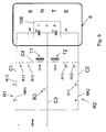
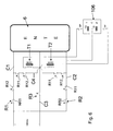
- the throw control (to the normal "N” or reverse “R” positions) is implemented by three printed circuit relays R1, R2, R3 whose normally open contacts NR1, RR2 or normally closed contacts N_ and R designated by R11 and R12 are introduced in the power circuit as shown in Figures 5 and 6 .
- two normally closed contacts N_ and R_, designated by R11 and R12, of the relays R1 and R2 hold the power source 112 shorted C4, when there is no control signal KN or KR and, as better explained hereafter, allow circulation of the alternating current of the monitoring circuit overlying the control circuit.
- the third relay R3 is an auxiliary protection relay which is energized in the control step by circuits other than those that control the relays R1 and R2.
- the protection relay R3, which is normally disenergized, is used to disconnect the wayside cable (by operating on the common return conductor C3) from the AC-DC converter 112 on the power output and thereby afford considerably improved safety conditions in the idle state, particularly on AC electrified lines, in case of cable insulation failure to the ground.
- the Actuating Board 12 is composed of an AC/DC power converter, whose output is vitally enabled by vital outputs of the zone logic computer 5; this "enabling" signal is indicated in Fig. 4 and Fig. 7 as ON_Vit.
- Fig. 2 and Fig. 4 shows that, from the moment in which the Zone Logic Computer (ZLC) exerts its control intention by transmitting the control signal Kn or Kr, energization of the unit 6 may only occur after a minimum time ⁇ .
- This "delay" is vitally ensured by a suitable delay circuit 612.
- a stop signal which has a protective function, for example, in case of abnormal power absorption by the unit and any other hazardous event, thereby preserving the integrity of the electronics of the Actuating Board 112 and/or the motor in the switch machine 6.
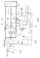
- Figure 7 shows the connections of the Monitoring and Diagnostics Board. As shown in Figure 7 , the board interfaces with:
- the local Logic Computer 5 through the three signals: KN, KR and DISALIM, transmitted to three vital inputs respectively and through the N and R signals received from two vital outputs;
- the board is composed of three functional sections:
- This section implements the TC and RC functions, i.e. transmission and reception of feedback signals for determining the position of the switch points. It accomplishes the turnout state monitoring functions, and communicates information through two position feedback signals KN and KR, connected to two vital inputs of the Zone Logic Computer (ZLC) 5.
- ZLC Zone Logic Computer
- the feedback signal is transmitted and received at about 400 Hz from and to the unit through transformers T1 and T2, the former T1 for the Normal switch point position signal KN and the latter T2 for the Reverse switch point position signal KR.
- the interface with the unit 6 may include 6 or 3 conductors, depending on whether or not a dedicated wire is used for feedback signals.
- FIGS 5 and 6 show two simplified diagrams of connection options.
- the transformers T1 and T2 for transmitting and receiving signals at 400 Hz are in the short-circuit branch C4 of the power output whereas, in the option with a separate cable for feedback signals C1', C2', C3', as shown in Figure 6 , the transformers T1 and T2 only have one point in common with the power circuit. Complete separation is not possible, due to the need for the Cable Insulation Check Section of the Monitoring Board, which is directly connected with the output of the Power Section, to check the efficiency of such insulation on both wires.
- the presence of the auxiliary control relays R1 and R2 allows the position monitoring transformers T1 and T2 to be connected in parallel with the power circuit, thereby avoiding the need for oversize series-connected transformers designed to have the DC current requested by the motor flowing therethrough.
- Figure 8 shows the block diagram of the switch point Position Monitoring Section.
- the two carrier generators 20 and 21 are amplitude modulated to provide an additional safety key, particularly needed in 50 Hz drive system applications.
- the feedback signal is transmitted and received through transformers, whose high isolation secondary windings are connected to the unit.
- the RIT timer block 613 maintains the corresponding vital input of the local Logic Computer (ZLC) 5 "low” for as long as required for the latter to detect it; thus, it allows the local computer 5 to detect any so-called "short monitoring failures".
- the module of the invention also has a Protection and Supervision Section.
- This section has operational supervision functions. These functions are accomplished by a microcontroller, and the section receives information by interfacing with the other functional blocks of the actuating module 1.
- the Protection Section energizes the control relay R1 or R2 according to the control intention (N and R signals) of the local Logic Computer (ZLC) 5; after the control step, the protection section also energizes the monitoring relays CTN or CTR, which further allow the feedback signal generated by one of the two transmitters T1 and T2 as described above to flow into a single receiver, which is always on.
- the Supervision and Protection Section is also designed to disable power delivery by the Actuating Board 12 during the control step, through the control protection function, by generating stop and DISALIM signals or a DISALIM signal only, in response to predetermined events.
- the events that trigger the control protection function are:
- the stop signal has the purpose of inhibiting the DC/DC converter 112" of the Actuating Board 12.
- the DISALIM signal is also generated to drive the third vital input of the local logic computer 5.
- the control protection function may be also performed outside the control step, in case of wayside cable failure, in the loop (not monitored) of the next control operation; in this case, the DISALIM signal is only generated.
- a periodic test is performed to check proper operation of the circuits designed to receive the control current.
- the Diagnostics Section receives the following parameters from the two Position Monitoring and Protection and Supervision Sections:
- the Diagnostics Section is mainly implemented in the microcontroller 24 that performs the Protection and Supervision functions, as shown in Figure 9 .
- Such microcontroller 24 directly acquires all the magnitudes to be subjected to diagnostics, interfaces with the Cable Insulation Check circuit 25 (CIC) and with the Echelon "node" 22, which is used as a communication unit on the Field Diagnostic Bus 8 (FDB) network.
- CIC Cable Insulation Check circuit
- FDB Field Diagnostic Bus 8
- microcontroller 24 performs tests on the cable insulation check circuit, either upon user's request (user interface panel) or in a periodic and automatic manner.
- the Cable Insulation Check (CIC) section 25 essentially comprises a 0.5 Kz square wave generator, connected to the input of the wayside cable C1, C2, C3 through a resistor of a suitable resistance, and a circuit for vector measurement of the absorbed current, which can detect cable insulation failure to ground, i.e. any reduction of cable insulation resistance, which can be configured in a step-wise manner.
- the switch machines 6 are controlled by the actuator 1 which provides power supply to the unit 6 and performs monitoring functions thereon.
- the interface is composed of two identical sections, one of which transmits at a certain time the indication of the (normal or reverse) position of the turnout unit 6 to the local Logic Computer (ZLC) 5.
- ZLC local Logic Computer
- the output transformer T1 of the normal position monitoring transmitter is closed on the remote capacitor CN. This triggers 400 Hz oscillation and enables relative position feedback (KN).
- the output transformer T2 of the reverse position monitoring transmitter is closed on a low impedance, in the classical case. Thus, its oscillator is off and the output KR is disabled.
- the above transmitter operates idly, thereby causing an oscillation at a frequency from 700 Hz to 2.5 kHz, which cannot enable the output KR.
- the Zone Logic Computer (ZLC) 5 Upon switching from normal to reverse, the Zone Logic Computer (ZLC) 5 enables its vital output (R); after a short time, the CTN relay will be disenergized and the normal KN feedback will be immediately lost, whereupon the control relay R1 is energized. Then, a control protection Stop signal is transmitted to enable operation of the DC/DC converter 112". After another short vital delay, the ON_Vit power supply is enabled, to energize first the protection relay R3 and then the section for controlling the power DC/DC converter 112". Now, the actuator provides a rated voltage of 150 VDC to the winding of the motor, which causes displacement in the "reverse" direction.
- the system logic cuts off the control operation thereby disabling the corresponding vital output (R).
- control and monitor switch machines that do not automatically cut off current upon termination of the control operation.
- a 6-wire connection is used, and the system may be configured to enable the monitoring relay CTR after a configurable delay from the time of closure of the control relay R2, regardless of whether the control current is cut off or not.
- the end of the control operation is determined as the monitoring frequency is reached and the corresponding feedback is obtained.
- the actuating module of the invention can handle abnormal operation statuses and ensure the highest safety.
- the former is the state in which the module operates for most of the time and is characterized by the lack of controls, with the monitored unit in the Normal or Reverse position; the latter operating state is the one in which the unit is controlled, and feedbacks are necessarily lost.
- abnormal states characterized by malfunctioning in the module, the unit and connection therebetween.
- This event may occur in response to a control operation.
- An unacknowledged control triggers a DISALIM signal.
- the turnout may be monitored or not.
- This event may occur during a control operation. Once the control operation timeout is reached, the unit is disenergized, the control operation is interrupted and a DISALIM signal is generated. The turnout may be monitored or not.
- This event may occur during a control operation. This protection does not disenergize the unit, whereby the module will try and terminate the control operation. When the latter is terminated, a DISALIM signal will be generated. The turnout may be monitored or not.
- This event may occur when there is no control operation and the turnout is monitored, in a normal or reverse position.
- the module triggers a DISALIM signal, to prevent voltage from being transmitted, during the next control operation, to a circuit that has no load.
- this protection may be excluded during configuration.
- This event occurs at the end of the last admitted control operation. Once this control operation is terminated, a DISALIM signal will be generated.
- the turnout may be monitored or not. This protection may be configured during setup.
- This event occurs during a control operation. This protection does not disenergize the unit, whereby the module will try and terminate the control operation. When the latter is terminated, a DISALIM signal will be generated. The turnout may be monitored or not.
- Periodic tests are performed for checking proper operation of control current measuring circuits. Whenever a test fails, a DISALIM signal is generated.
Landscapes
- Engineering & Computer Science (AREA)
- Mechanical Engineering (AREA)
- Health & Medical Sciences (AREA)
- Biomedical Technology (AREA)
- General Health & Medical Sciences (AREA)
- Train Traffic Observation, Control, And Security (AREA)
- Remote Monitoring And Control Of Power-Distribution Networks (AREA)
- Electric Propulsion And Braking For Vehicles (AREA)
Priority Applications (6)
| Application Number | Priority Date | Filing Date | Title |
|---|---|---|---|
| AT07425275T ATE449717T1 (de) | 2007-05-10 | 2007-05-10 | Betätigungs- und überwachungsmodul für bedieneinheiten von streckenseitigen anlagen von eisenbahnsystemen oder dergleichen |
| EP07425275A EP1990252B1 (fr) | 2007-05-10 | 2007-05-10 | Module d'actionnement et de surveillance pour des unités opérationnelles des équipements de voie pour systèmes ferroviaires ou similaires |
| DE602007003451T DE602007003451D1 (de) | 2007-05-10 | 2007-05-10 | Betätigungs- und Überwachungsmodul für Bedieneinheiten von streckenseitigen Anlagen von Eisenbahnsystemen oder dergleichen |
| ES07425275T ES2337202T3 (es) | 2007-05-10 | 2007-05-10 | Modulo de accionamiento y de vigilancia para unidades de funcionamiento de equipos de via de sistemas ferroviarios o similares. |
| MA30917A MA30009B1 (fr) | 2007-05-10 | 2008-05-09 | Module de commande et de surveillance, particulierement pour unites d'actionnement, c-a-d. equipement de bordure de voie, de reseaux de chemins de fer ou similaires. |
| NO20082183A NO20082183L (no) | 2007-05-10 | 2008-05-13 | Aktiverings- og overvakningsmodul, spesielt for driftsenheter, for eksempel veikantsutstyr, til jernbanesystemer og lignende |
Applications Claiming Priority (1)
| Application Number | Priority Date | Filing Date | Title |
|---|---|---|---|
| EP07425275A EP1990252B1 (fr) | 2007-05-10 | 2007-05-10 | Module d'actionnement et de surveillance pour des unités opérationnelles des équipements de voie pour systèmes ferroviaires ou similaires |
Publications (2)
| Publication Number | Publication Date |
|---|---|
| EP1990252A1 true EP1990252A1 (fr) | 2008-11-12 |
| EP1990252B1 EP1990252B1 (fr) | 2009-11-25 |
Family
ID=38520555
Family Applications (1)
| Application Number | Title | Priority Date | Filing Date |
|---|---|---|---|
| EP07425275A Not-in-force EP1990252B1 (fr) | 2007-05-10 | 2007-05-10 | Module d'actionnement et de surveillance pour des unités opérationnelles des équipements de voie pour systèmes ferroviaires ou similaires |
Country Status (6)
| Country | Link |
|---|---|
| EP (1) | EP1990252B1 (fr) |
| AT (1) | ATE449717T1 (fr) |
| DE (1) | DE602007003451D1 (fr) |
| ES (1) | ES2337202T3 (fr) |
| MA (1) | MA30009B1 (fr) |
| NO (1) | NO20082183L (fr) |
Cited By (13)
| Publication number | Priority date | Publication date | Assignee | Title |
|---|---|---|---|---|
| EP2236389A3 (fr) * | 2009-03-30 | 2011-05-25 | Siemens Schweiz AG | Procédé de dépôt de signalements des perturbations d'une unité de fonctionnement décentralisée dans un système de sécurisation pour trafic sur rails |
| NL2010803A (nl) * | 2012-10-04 | 2013-06-10 | Volkerrail Nederland B V | Systeem voor het bewaken van de bedrijfsfuncties van bewegende componenten van een spoorweg. |
| WO2013110859A1 (fr) * | 2012-01-27 | 2013-08-01 | Vr Track Oy | Agencement pour aiguillage de trafic ferroviaire |
| CN103236204A (zh) * | 2013-04-14 | 2013-08-07 | 柳州铁道职业技术学院 | Zpw-2000a型移频综合实训平台 |
| FR3012100A1 (fr) * | 2013-10-18 | 2015-04-24 | Scle Systemes Pour Le Ferroviaire Et L En | Dispositif pour securiser un systeme utilisant des commandes electriques |
| EP3150461A1 (fr) * | 2015-10-02 | 2017-04-05 | Siemens Schweiz AG | Système et procédé d'élimination automatique d'une tension induite excessive dans un bus de puissance |
| CN112693495A (zh) * | 2021-01-08 | 2021-04-23 | 北京全路通信信号研究设计院集团有限公司 | 一种无节点分布式道岔安全驱采控制系统 |
| CN112865285A (zh) * | 2019-11-27 | 2021-05-28 | 中车唐山机车车辆有限公司 | 控制电路 |
| CN114399942A (zh) * | 2022-02-18 | 2022-04-26 | 浙江众合科技股份有限公司 | 一种能自动切换表示的三相五线制道岔板卡仿真电路 |
| CN114475701A (zh) * | 2022-01-07 | 2022-05-13 | 北京全路通信信号研究设计院集团有限公司 | 一种用于有轨车辆的分布式道岔控制系统 |
| CN114670894A (zh) * | 2022-03-03 | 2022-06-28 | 浙江众合科技股份有限公司 | 一种全电子联锁道岔板一驱到底功能电路 |
| CN115754559A (zh) * | 2022-11-28 | 2023-03-07 | 卡斯柯信号有限公司 | 一种基于二乘二取二架构的零散采集系统 |
| CN116853315A (zh) * | 2023-07-19 | 2023-10-10 | 卡斯柯信号有限公司 | 一种基于脉冲发生器的直流转辙机控制器 |
Families Citing this family (3)
| Publication number | Priority date | Publication date | Assignee | Title |
|---|---|---|---|---|
| RU204121U1 (ru) * | 2021-03-24 | 2021-05-07 | Открытое акционерное общество "Объединенные электротехнические заводы" | Блок конденсаторный дешифратора типа ДА |
| CN113759772B (zh) * | 2021-08-16 | 2024-01-30 | 北京和利时系统工程有限公司 | 一种三相五线制交流转辙机的自动模拟装置和操作方法 |
| CN113805562B (zh) * | 2021-08-16 | 2023-06-02 | 北京和利时系统工程有限公司 | 一种三相五线制交流转辙机的模拟装置和操作方法 |
Citations (5)
| Publication number | Priority date | Publication date | Assignee | Title |
|---|---|---|---|---|
| CH302004A (de) * | 1951-04-12 | 1954-09-30 | Siemens Ag | Gleichstrom-Antriebseinrichtung für Weichen und Signale bei Eisenbahnstellwerken. |
| EP0749883A2 (fr) | 1995-06-20 | 1996-12-27 | ANSALDO TRASPORTI S.p.A. | Système de commande pour des aiguillages de chemin de fer |
| DE19606894A1 (de) * | 1996-02-13 | 1997-08-14 | Siemens Ag | Einrichtung zur signaltechnisch sicheren Steuerung und Überwachung elektrischer Verbraucher im Eisenbahnwesen |
| WO2001054262A1 (fr) | 2000-01-24 | 2001-07-26 | Union Switch & Signal, Inc. | Dispositif de commande du moteur d'un appareil electrique de manoeuvre d'aiguillage de chemin de fer |
| EP1785332A1 (fr) * | 2005-11-15 | 2007-05-16 | Alstom Ferroviaria S.P.A. | Module d'actionnement et de surveillance, en particulier pour des unités opérationnelles, par exemple des équipements de voie, pour les systèmes ferroviaires ou similaires |
-
2007
- 2007-05-10 EP EP07425275A patent/EP1990252B1/fr not_active Not-in-force
- 2007-05-10 AT AT07425275T patent/ATE449717T1/de not_active IP Right Cessation
- 2007-05-10 DE DE602007003451T patent/DE602007003451D1/de not_active Expired - Fee Related
- 2007-05-10 ES ES07425275T patent/ES2337202T3/es active Active
-
2008
- 2008-05-09 MA MA30917A patent/MA30009B1/fr unknown
- 2008-05-13 NO NO20082183A patent/NO20082183L/no not_active Application Discontinuation
Patent Citations (5)
| Publication number | Priority date | Publication date | Assignee | Title |
|---|---|---|---|---|
| CH302004A (de) * | 1951-04-12 | 1954-09-30 | Siemens Ag | Gleichstrom-Antriebseinrichtung für Weichen und Signale bei Eisenbahnstellwerken. |
| EP0749883A2 (fr) | 1995-06-20 | 1996-12-27 | ANSALDO TRASPORTI S.p.A. | Système de commande pour des aiguillages de chemin de fer |
| DE19606894A1 (de) * | 1996-02-13 | 1997-08-14 | Siemens Ag | Einrichtung zur signaltechnisch sicheren Steuerung und Überwachung elektrischer Verbraucher im Eisenbahnwesen |
| WO2001054262A1 (fr) | 2000-01-24 | 2001-07-26 | Union Switch & Signal, Inc. | Dispositif de commande du moteur d'un appareil electrique de manoeuvre d'aiguillage de chemin de fer |
| EP1785332A1 (fr) * | 2005-11-15 | 2007-05-16 | Alstom Ferroviaria S.P.A. | Module d'actionnement et de surveillance, en particulier pour des unités opérationnelles, par exemple des équipements de voie, pour les systèmes ferroviaires ou similaires |
Cited By (22)
| Publication number | Priority date | Publication date | Assignee | Title |
|---|---|---|---|---|
| EP2236389A3 (fr) * | 2009-03-30 | 2011-05-25 | Siemens Schweiz AG | Procédé de dépôt de signalements des perturbations d'une unité de fonctionnement décentralisée dans un système de sécurisation pour trafic sur rails |
| WO2013110859A1 (fr) * | 2012-01-27 | 2013-08-01 | Vr Track Oy | Agencement pour aiguillage de trafic ferroviaire |
| NL2010803A (nl) * | 2012-10-04 | 2013-06-10 | Volkerrail Nederland B V | Systeem voor het bewaken van de bedrijfsfuncties van bewegende componenten van een spoorweg. |
| NL2011826A (nl) * | 2012-10-04 | 2014-04-07 | Volkerrail Nederland B V | Systeem en werkwijze voor het bewaken van de bedrijfsfuncties van mechanisch bewogen componenten van een spoorweg, door relaissensoren en een actuatorsensor. |
| EP2716518A1 (fr) * | 2012-10-04 | 2014-04-09 | VolkerRail Nederland BV | Système pour surveiller les fonctions opérationnelles de composants mobiles d'une voie ferrée |
| CN103236204A (zh) * | 2013-04-14 | 2013-08-07 | 柳州铁道职业技术学院 | Zpw-2000a型移频综合实训平台 |
| CN103236204B (zh) * | 2013-04-14 | 2015-05-06 | 柳州铁道职业技术学院 | Zpw-2000a型移频综合实训平台 |
| FR3012100A1 (fr) * | 2013-10-18 | 2015-04-24 | Scle Systemes Pour Le Ferroviaire Et L En | Dispositif pour securiser un systeme utilisant des commandes electriques |
| EP3150461A1 (fr) * | 2015-10-02 | 2017-04-05 | Siemens Schweiz AG | Système et procédé d'élimination automatique d'une tension induite excessive dans un bus de puissance |
| WO2017054951A1 (fr) * | 2015-10-02 | 2017-04-06 | Siemens Schweiz Ag | Système et procédé permettant l'élimination automatique d'une tension pertubatrice excessive dans un bus d'alimentation |
| CN112865285B (zh) * | 2019-11-27 | 2023-10-31 | 中车唐山机车车辆有限公司 | 控制电路 |
| CN112865285A (zh) * | 2019-11-27 | 2021-05-28 | 中车唐山机车车辆有限公司 | 控制电路 |
| CN112693495A (zh) * | 2021-01-08 | 2021-04-23 | 北京全路通信信号研究设计院集团有限公司 | 一种无节点分布式道岔安全驱采控制系统 |
| CN112693495B (zh) * | 2021-01-08 | 2023-05-16 | 北京全路通信信号研究设计院集团有限公司 | 一种无节点分布式道岔安全驱采控制系统 |
| CN114475701A (zh) * | 2022-01-07 | 2022-05-13 | 北京全路通信信号研究设计院集团有限公司 | 一种用于有轨车辆的分布式道岔控制系统 |
| CN114475701B (zh) * | 2022-01-07 | 2024-01-19 | 北京全路通信信号研究设计院集团有限公司 | 一种用于有轨车辆的分布式道岔控制系统 |
| CN114399942B (zh) * | 2022-02-18 | 2023-09-05 | 浙江众合科技股份有限公司 | 一种能自动切换表示的三相五线制道岔板卡仿真电路 |
| CN114399942A (zh) * | 2022-02-18 | 2022-04-26 | 浙江众合科技股份有限公司 | 一种能自动切换表示的三相五线制道岔板卡仿真电路 |
| CN114670894A (zh) * | 2022-03-03 | 2022-06-28 | 浙江众合科技股份有限公司 | 一种全电子联锁道岔板一驱到底功能电路 |
| CN114670894B (zh) * | 2022-03-03 | 2024-06-04 | 浙江众合科技股份有限公司 | 一种全电子联锁道岔板一驱到底功能电路 |
| CN115754559A (zh) * | 2022-11-28 | 2023-03-07 | 卡斯柯信号有限公司 | 一种基于二乘二取二架构的零散采集系统 |
| CN116853315A (zh) * | 2023-07-19 | 2023-10-10 | 卡斯柯信号有限公司 | 一种基于脉冲发生器的直流转辙机控制器 |
Also Published As
| Publication number | Publication date |
|---|---|
| MA30009B1 (fr) | 2008-12-01 |
| NO20082183L (no) | 2008-11-11 |
| EP1990252B1 (fr) | 2009-11-25 |
| ATE449717T1 (de) | 2009-12-15 |
| ES2337202T3 (es) | 2010-04-21 |
| DE602007003451D1 (de) | 2010-01-07 |
Similar Documents
| Publication | Publication Date | Title |
|---|---|---|
| EP1990252B1 (fr) | Module d'actionnement et de surveillance pour des unités opérationnelles des équipements de voie pour systèmes ferroviaires ou similaires | |
| CN109278802B (zh) | 一种交流道岔装置、系统及其控制方法 | |
| CN109278801B (zh) | 一种道岔表示装置 | |
| CN203827308U (zh) | 防止输入信号输出的装置、为驱动电机提供输出电压的装置以及电机驱动系统 | |
| CN109050539B (zh) | 一种站台门联动控制系统 | |
| US8566415B2 (en) | Safe torque off over network wiring | |
| CN111409668A (zh) | 一种道岔控制系统 | |
| CN107891884A (zh) | 全电子道岔位置检测装置 | |
| CN109075564A (zh) | 用于将逆变器的相主动短接的系统以及机动车驱动装置 | |
| RU2012129545A (ru) | Защита параллельных линий электрической сети энергоснабжения | |
| CN108032870A (zh) | 道岔控制模块及其全电子化的实现方法 | |
| RU2194645C2 (ru) | Схема для управления и контроля стрелочных приводов | |
| WO2006127066A2 (fr) | Relais vital electronique | |
| CN109585219A (zh) | 安全开关 | |
| CN109278800A (zh) | 一种直流转辙机控制系统和控制方法 | |
| CN113859304B (zh) | 道岔监控和控制方法及装置 | |
| JP2003237579A (ja) | 鉄道信号保安装置用知的端末 | |
| US7193510B2 (en) | Safety interlock circuit with diagnostics requiring no extra signal wires | |
| EP1785332B1 (fr) | Module d'actionnement et de surveillance, en particulier pour des unités opérationnelles, par exemple des équipements de voie, pour les systèmes ferroviaires ou similaires | |
| CN105652191B (zh) | 一种安全回路状态监测系统 | |
| KR101036025B1 (ko) | 전력선통신 시스템. | |
| CN108879611B (zh) | 一种永磁电机系统的故障控制方法及系统 | |
| CN208570471U (zh) | 一种电动接地开关控制装置 | |
| KR100844755B1 (ko) | 무절연 궤도회로 랙용 듀얼 에스엠피에스 장치 | |
| CN102832798A (zh) | 一种上电缓冲控制电路及其控制方法 |
Legal Events
| Date | Code | Title | Description |
|---|---|---|---|
| PUAI | Public reference made under article 153(3) epc to a published international application that has entered the european phase |
Free format text: ORIGINAL CODE: 0009012 |
|
| 17P | Request for examination filed |
Effective date: 20080408 |
|
| AK | Designated contracting states |
Kind code of ref document: A1 Designated state(s): AT BE BG CH CY CZ DE DK EE ES FI FR GB GR HU IE IS IT LI LT LU LV MC MT NL PL PT RO SE SI SK TR |
|
| AX | Request for extension of the european patent |
Extension state: AL BA HR MK RS |
|
| AKX | Designation fees paid |
Designated state(s): AT BE BG CH CY CZ DE DK EE ES FI FR GB GR HU IE IS IT LI LT LU LV MC MT NL PL PT RO SE SI SK TR |
|
| GRAP | Despatch of communication of intention to grant a patent |
Free format text: ORIGINAL CODE: EPIDOSNIGR1 |
|
| GRAS | Grant fee paid |
Free format text: ORIGINAL CODE: EPIDOSNIGR3 |
|
| GRAA | (expected) grant |
Free format text: ORIGINAL CODE: 0009210 |
|
| AK | Designated contracting states |
Kind code of ref document: B1 Designated state(s): AT BE BG CH CY CZ DE DK EE ES FI FR GB GR HU IE IS IT LI LT LU LV MC MT NL PL PT RO SE SI SK TR |
|
| REG | Reference to a national code |
Ref country code: GB Ref legal event code: FG4D |
|
| REG | Reference to a national code |
Ref country code: CH Ref legal event code: EP |
|
| REG | Reference to a national code |
Ref country code: IE Ref legal event code: FG4D |
|
| REF | Corresponds to: |
Ref document number: 602007003451 Country of ref document: DE Date of ref document: 20100107 Kind code of ref document: P |
|
| REG | Reference to a national code |
Ref country code: GR Ref legal event code: EP Ref document number: 20100400354 Country of ref document: GR |
|
| REG | Reference to a national code |
Ref country code: NL Ref legal event code: VDEP Effective date: 20091125 |
|
| REG | Reference to a national code |
Ref country code: ES Ref legal event code: FG2A Ref document number: 2337202 Country of ref document: ES Kind code of ref document: T3 |
|
| LTIE | Lt: invalidation of european patent or patent extension |
Effective date: 20091125 |
|
| PG25 | Lapsed in a contracting state [announced via postgrant information from national office to epo] |
Ref country code: LT Free format text: LAPSE BECAUSE OF FAILURE TO SUBMIT A TRANSLATION OF THE DESCRIPTION OR TO PAY THE FEE WITHIN THE PRESCRIBED TIME-LIMIT Effective date: 20091125 Ref country code: SE Free format text: LAPSE BECAUSE OF FAILURE TO SUBMIT A TRANSLATION OF THE DESCRIPTION OR TO PAY THE FEE WITHIN THE PRESCRIBED TIME-LIMIT Effective date: 20091125 Ref country code: PT Free format text: LAPSE BECAUSE OF FAILURE TO SUBMIT A TRANSLATION OF THE DESCRIPTION OR TO PAY THE FEE WITHIN THE PRESCRIBED TIME-LIMIT Effective date: 20100325 Ref country code: FI Free format text: LAPSE BECAUSE OF FAILURE TO SUBMIT A TRANSLATION OF THE DESCRIPTION OR TO PAY THE FEE WITHIN THE PRESCRIBED TIME-LIMIT Effective date: 20091125 Ref country code: IS Free format text: LAPSE BECAUSE OF FAILURE TO SUBMIT A TRANSLATION OF THE DESCRIPTION OR TO PAY THE FEE WITHIN THE PRESCRIBED TIME-LIMIT Effective date: 20100325 |
|
| PG25 | Lapsed in a contracting state [announced via postgrant information from national office to epo] |
Ref country code: CY Free format text: LAPSE BECAUSE OF FAILURE TO SUBMIT A TRANSLATION OF THE DESCRIPTION OR TO PAY THE FEE WITHIN THE PRESCRIBED TIME-LIMIT Effective date: 20091125 Ref country code: LV Free format text: LAPSE BECAUSE OF FAILURE TO SUBMIT A TRANSLATION OF THE DESCRIPTION OR TO PAY THE FEE WITHIN THE PRESCRIBED TIME-LIMIT Effective date: 20091125 Ref country code: SI Free format text: LAPSE BECAUSE OF FAILURE TO SUBMIT A TRANSLATION OF THE DESCRIPTION OR TO PAY THE FEE WITHIN THE PRESCRIBED TIME-LIMIT Effective date: 20091125 Ref country code: PL Free format text: LAPSE BECAUSE OF FAILURE TO SUBMIT A TRANSLATION OF THE DESCRIPTION OR TO PAY THE FEE WITHIN THE PRESCRIBED TIME-LIMIT Effective date: 20091125 |
|
| PG25 | Lapsed in a contracting state [announced via postgrant information from national office to epo] |
Ref country code: BE Free format text: LAPSE BECAUSE OF FAILURE TO SUBMIT A TRANSLATION OF THE DESCRIPTION OR TO PAY THE FEE WITHIN THE PRESCRIBED TIME-LIMIT Effective date: 20091125 Ref country code: AT Free format text: LAPSE BECAUSE OF FAILURE TO SUBMIT A TRANSLATION OF THE DESCRIPTION OR TO PAY THE FEE WITHIN THE PRESCRIBED TIME-LIMIT Effective date: 20091125 |
|
| PG25 | Lapsed in a contracting state [announced via postgrant information from national office to epo] |
Ref country code: BG Free format text: LAPSE BECAUSE OF FAILURE TO SUBMIT A TRANSLATION OF THE DESCRIPTION OR TO PAY THE FEE WITHIN THE PRESCRIBED TIME-LIMIT Effective date: 20100225 Ref country code: NL Free format text: LAPSE BECAUSE OF FAILURE TO SUBMIT A TRANSLATION OF THE DESCRIPTION OR TO PAY THE FEE WITHIN THE PRESCRIBED TIME-LIMIT Effective date: 20091125 Ref country code: EE Free format text: LAPSE BECAUSE OF FAILURE TO SUBMIT A TRANSLATION OF THE DESCRIPTION OR TO PAY THE FEE WITHIN THE PRESCRIBED TIME-LIMIT Effective date: 20091125 Ref country code: DK Free format text: LAPSE BECAUSE OF FAILURE TO SUBMIT A TRANSLATION OF THE DESCRIPTION OR TO PAY THE FEE WITHIN THE PRESCRIBED TIME-LIMIT Effective date: 20091125 Ref country code: RO Free format text: LAPSE BECAUSE OF FAILURE TO SUBMIT A TRANSLATION OF THE DESCRIPTION OR TO PAY THE FEE WITHIN THE PRESCRIBED TIME-LIMIT Effective date: 20091125 |
|
| PG25 | Lapsed in a contracting state [announced via postgrant information from national office to epo] |
Ref country code: CZ Free format text: LAPSE BECAUSE OF FAILURE TO SUBMIT A TRANSLATION OF THE DESCRIPTION OR TO PAY THE FEE WITHIN THE PRESCRIBED TIME-LIMIT Effective date: 20091125 Ref country code: SK Free format text: LAPSE BECAUSE OF FAILURE TO SUBMIT A TRANSLATION OF THE DESCRIPTION OR TO PAY THE FEE WITHIN THE PRESCRIBED TIME-LIMIT Effective date: 20091125 |
|
| PLBE | No opposition filed within time limit |
Free format text: ORIGINAL CODE: 0009261 |
|
| STAA | Information on the status of an ep patent application or granted ep patent |
Free format text: STATUS: NO OPPOSITION FILED WITHIN TIME LIMIT |
|
| 26N | No opposition filed |
Effective date: 20100826 |
|
| PG25 | Lapsed in a contracting state [announced via postgrant information from national office to epo] |
Ref country code: MC Free format text: LAPSE BECAUSE OF NON-PAYMENT OF DUE FEES Effective date: 20100531 |
|
| REG | Reference to a national code |
Ref country code: FR Ref legal event code: ST Effective date: 20110131 |
|
| PG25 | Lapsed in a contracting state [announced via postgrant information from national office to epo] |
Ref country code: IT Free format text: LAPSE BECAUSE OF NON-PAYMENT OF DUE FEES Effective date: 20100510 |
|
| PG25 | Lapsed in a contracting state [announced via postgrant information from national office to epo] |
Ref country code: DE Free format text: LAPSE BECAUSE OF NON-PAYMENT OF DUE FEES Effective date: 20101201 Ref country code: MT Free format text: LAPSE BECAUSE OF FAILURE TO SUBMIT A TRANSLATION OF THE DESCRIPTION OR TO PAY THE FEE WITHIN THE PRESCRIBED TIME-LIMIT Effective date: 20091125 Ref country code: IE Free format text: LAPSE BECAUSE OF NON-PAYMENT OF DUE FEES Effective date: 20100510 |
|
| PG25 | Lapsed in a contracting state [announced via postgrant information from national office to epo] |
Ref country code: FR Free format text: LAPSE BECAUSE OF NON-PAYMENT OF DUE FEES Effective date: 20100531 |
|
| REG | Reference to a national code |
Ref country code: CH Ref legal event code: PL |
|
| GBPC | Gb: european patent ceased through non-payment of renewal fee |
Effective date: 20110510 |
|
| PG25 | Lapsed in a contracting state [announced via postgrant information from national office to epo] |
Ref country code: LI Free format text: LAPSE BECAUSE OF NON-PAYMENT OF DUE FEES Effective date: 20110531 Ref country code: CH Free format text: LAPSE BECAUSE OF NON-PAYMENT OF DUE FEES Effective date: 20110531 |
|
| PG25 | Lapsed in a contracting state [announced via postgrant information from national office to epo] |
Ref country code: GB Free format text: LAPSE BECAUSE OF NON-PAYMENT OF DUE FEES Effective date: 20110510 |
|
| PG25 | Lapsed in a contracting state [announced via postgrant information from national office to epo] |
Ref country code: LU Free format text: LAPSE BECAUSE OF NON-PAYMENT OF DUE FEES Effective date: 20100510 Ref country code: HU Free format text: LAPSE BECAUSE OF FAILURE TO SUBMIT A TRANSLATION OF THE DESCRIPTION OR TO PAY THE FEE WITHIN THE PRESCRIBED TIME-LIMIT Effective date: 20100526 |
|
| PGFP | Annual fee paid to national office [announced via postgrant information from national office to epo] |
Ref country code: IT Payment date: 20210527 Year of fee payment: 15 Ref country code: GR Payment date: 20210511 Year of fee payment: 15 |
|
| PGFP | Annual fee paid to national office [announced via postgrant information from national office to epo] |
Ref country code: TR Payment date: 20210430 Year of fee payment: 15 |
|
| PGFP | Annual fee paid to national office [announced via postgrant information from national office to epo] |
Ref country code: ES Payment date: 20210721 Year of fee payment: 15 |
|
| PG25 | Lapsed in a contracting state [announced via postgrant information from national office to epo] |
Ref country code: GR Free format text: LAPSE BECAUSE OF NON-PAYMENT OF DUE FEES Effective date: 20221208 |
|
| REG | Reference to a national code |
Ref country code: ES Ref legal event code: FD2A Effective date: 20230627 |
|
| PG25 | Lapsed in a contracting state [announced via postgrant information from national office to epo] |
Ref country code: ES Free format text: LAPSE BECAUSE OF NON-PAYMENT OF DUE FEES Effective date: 20220511 |
|
| PG25 | Lapsed in a contracting state [announced via postgrant information from national office to epo] |
Ref country code: TR Free format text: LAPSE BECAUSE OF NON-PAYMENT OF DUE FEES Effective date: 20220510 |
|
| PG25 | Lapsed in a contracting state [announced via postgrant information from national office to epo] |
Ref country code: IT Free format text: LAPSE BECAUSE OF NON-PAYMENT OF DUE FEES Effective date: 20220510 |