EP1990268A2 - Dérailleur avant pour bicyclette - Google Patents
Dérailleur avant pour bicyclette Download PDFInfo
- Publication number
- EP1990268A2 EP1990268A2 EP08005645A EP08005645A EP1990268A2 EP 1990268 A2 EP1990268 A2 EP 1990268A2 EP 08005645 A EP08005645 A EP 08005645A EP 08005645 A EP08005645 A EP 08005645A EP 1990268 A2 EP1990268 A2 EP 1990268A2
- Authority
- EP
- European Patent Office
- Prior art keywords
- connecting rod
- fixed member
- derailleur
- articulation
- pin
- Prior art date
- Legal status (The legal status is an assumption and is not a legal conclusion. Google has not performed a legal analysis and makes no representation as to the accuracy of the status listed.)
- Granted
Links
- 230000005540 biological transmission Effects 0.000 claims description 5
- 230000008878 coupling Effects 0.000 description 4
- 238000010168 coupling process Methods 0.000 description 4
- 238000005859 coupling reaction Methods 0.000 description 4
- 238000005452 bending Methods 0.000 description 1
- 230000001419 dependent effect Effects 0.000 description 1
- 230000001788 irregular Effects 0.000 description 1
- 238000000034 method Methods 0.000 description 1
Images


Classifications
-
- B—PERFORMING OPERATIONS; TRANSPORTING
- B62—LAND VEHICLES FOR TRAVELLING OTHERWISE THAN ON RAILS
- B62M—RIDER PROPULSION OF WHEELED VEHICLES OR SLEDGES; POWERED PROPULSION OF SLEDGES OR SINGLE-TRACK CYCLES; TRANSMISSIONS SPECIALLY ADAPTED FOR SUCH VEHICLES
- B62M9/00—Transmissions characterised by use of an endless chain, belt, or the like
- B62M9/04—Transmissions characterised by use of an endless chain, belt, or the like of changeable ratio
- B62M9/06—Transmissions characterised by use of an endless chain, belt, or the like of changeable ratio using a single chain, belt, or the like
- B62M9/10—Transmissions characterised by use of an endless chain, belt, or the like of changeable ratio using a single chain, belt, or the like involving different-sized wheels, e.g. rear sprocket chain wheels selectively engaged by the chain, belt, or the like
- B62M9/12—Transmissions characterised by use of an endless chain, belt, or the like of changeable ratio using a single chain, belt, or the like involving different-sized wheels, e.g. rear sprocket chain wheels selectively engaged by the chain, belt, or the like the chain, belt, or the like being laterally shiftable, e.g. using a rear derailleur
- B62M9/131—Front derailleurs
- B62M9/134—Mechanisms for shifting laterally
- B62M9/1342—Mechanisms for shifting laterally characterised by the linkage mechanisms
Definitions
- the present invention concerns a front derailleur for a bicycle.
- front derailleurs are used to move the chain during travel from a toothed wheel of the bottom bracket to another one having a different diameter to carry out gearshifting, varying the transmission ratio.
- the derailleur comprises a chain guide above the chain and a chain guide positioning mechanism, normally an articulated parallelogram mechanism, which is fixed to the bicycle frame along the tube that connects the bottom bracket to the saddle (seat-tube).
- a chain guide positioning mechanism normally an articulated parallelogram mechanism
- the chain guide is formed from an inner plate and an outer plate facing one another and substantially parallel.
- the inner plate acts thrusting upon the chain to make it pass from a wheel having a small diameter to one having a larger diameter (upward gearshifting) and the outer plate acts thrusting upon the chain to make it pass from a wheel having a larger diameter to one having a smaller diameter (downward gearshifting).
- a known derailleur is described in US 7,081,058 and essentially comprises a chain guide positioning mechanism that comprises an articulated quadrilateral formed from a fixed member (first side) firmly connected to a strap for connection around the seat-tube, from two connecting rods (inner connecting rod and outer connecting rod, which form other two sides of the parallelogram) and from the body of the chain guide itself (which forms the fourth side and completes the articulated parallelogram), articulated along four axes A, B, C and D, parallel to one another.
- the outer connecting rod is upper hinged to the fixed member about the second axis B and extends on top beyond the second axis B with an actuation arm to the end of which the actuation cable of the derailleur is connected.
- the cable is laterally connected to the end of the actuation arm, so that the cable itself does not interfere with the positioning mechanism below.
- the outer connecting rod is hinged to a top end of the fixed member and receives such an end in an opening defined by two of its flanges 106a and 106b that laterally embrace the top end of the fixed member.
- the top end of the fixed member and the two flanges 106a and 106b receives an articulation pin 70 along the axis B in respective aligned holes.
- the inventors of the present patent application have found a drawback in such a type of derailleur.
- the bending moment caused by the traction of the command cable creates a non-uniform stress: when, indeed, the cable is pulled to move the chain guide, the stress induced by the cable on the end of the actuation arm is transmitted to the articulation pin close to the two flanges 106a and 106b and acts upon the ends of the pin 70; one end of the pin 70, the one facing towards the side in which the actuation arm extends, close to the flange 106b, is biased more than the other.
- the continuous stresses of the pin at its ends, in particular at its most biased end can cause irregular wearing of the pin and/or of the flanges or even lead to breaking.
- the problem forming the basis of the present invention is that of making a derailleur that does not have the drawbacks of known derailleurs.
- the present invention concerns, in its most general terms, a derailleur according to claim 1; preferred optional characteristics are outlined in the dependent claims.
- a front derailleur for a bicycle comprises:
- the thrusting area on the actuation arm of the first connecting rod comprises a hook for a derailleur command cable
- the derailleur comprises an elastic return member, acting on the articulated quadrilateral in the direction to push the chain-guide towards said first position, in which the thrust applied by the cable to the hook acts in the opposite direction to the return of the elastic return member.
- the thrusting area can be a toothed sector engaged with a driving screw.
- the flanges of the first forked structure are provided with respective holes aligned along the first articulation axis and the first connecting rod comprises a hole aligned with the first articulation axis, a pin being inserted into the two holes of the first forked structure and into the hole of the first connecting rod.
- the pin it is possible for the pin to be formed in one piece with the connecting rod and for the flanges to consequently be in two pieces, so as to be able to be mounted on the pin; or else, it is possible for the pin -possibly in two pieces - to be formed in one piece with the flanges and for the connecting rod to consequently be made in two pieces, so as to be able to be mounted on the pin.
- the first connecting rod comprises a main arm extending between the first articulation axis and a second of said four articulation axes, between the first connecting rod and the mobile member, and the main arm and the actuation arm substantially extend in the same plane perpendicular to the four articulation axes.
- the expression "substantially extend in the same plane” must not be taken here in the literal sense that the first connecting rod has substantially zero thickness in the direction of the articulation axes, but rather in the sense that the first connecting rod extends substantially to the same extent on one side as on the other, in the direction of the articulation axes, i.e. that it does not have canti-levered portions.
- the first connecting rod has a very regular and uniform configuration, such as to regularly and uniformly transmit to the pin the stresses induced by the command cable.
- the fixed member comprises a second forked structure that embraces the second connecting rod
- the second forked structure comprises two opposite flanges; more preferably, the flanges of the second forked structure are provided with respective holes aligned along the third articulation axis
- the second connecting rod comprises a hole aligned with the third articulation axis
- a pin is inserted into the two holes of the second forked structure and into the hole of the second connecting rod.
- the pin it is possible for the pin to be formed in one piece with the connecting rod and for the flanges to consequently be in two pieces, so as to be able to be mounted on the pin; or else, it is possible for the pin - possibly in two pieces - to be formed in one piece with the flanges and for the connecting rod to consequently be made in two pieces, so as to be able to be mounted on the pin.
- the fixed member comprises a canti-levered pin
- the second connecting rod comprises a hole aligned with the third articulation axis, inserted on the canti-levered pin of the fixed member.
- the mobile member comprises two opposite flanges perforated along the fourth articulation axis, in which the second connecting rod comprises a hole aligned with the fourth articulation axis, and in which a pin is inserted into the flanges and into the hole of the second connecting rod and, more preferably, the elastic return member is a helical spring, mounted on the pin and provided with two ends, one engaged with an abutment tooth formed on the second connecting rod, the other engaged with an abutment portion formed on the mobile member.
- the fixed member comprises a cylindrical portion for a braze-on attachment to the bicycle frame.
- the fixed member comprises two semi-circular portions articulated together and a locking element for locking such semi-circular portions about the part of bicycle frame; in this case, more preferably, the fixed member is formed in one piece with one of the two articulated semi-circular portions.
- the second connecting rod is substantially S-shaped, between a third and a fourth of said four articulation axes, and extends between a first plane at the third articulation axis and a second plane at the fourth articulation axis, and in which the first and the second plane of the second connecting rod are perpendicular to the four articulation axes and are spaced apart by a predetermined distance.
- Figures 1 to 4 show a derailleur 10, in particular a front derailleur suitable for being mounted on a bicycle.
- the derailleur 10 comprises a chain guide 11, which is suitable for sliding engagement with a transmission chain of the bicycle to move the chain from a first position and at least one second position, corresponding to distinct transmission ratios; neither the chain nor other parts of the bicycle are shown in the drawings, both for the sake of simplicity of illustration, and because they are per se known and do not form part of the invention.
- the chain guide 11 forms part of a mobile member 12 of an actuation mechanism that also includes a fixed member 13 (more clearly visible in figures 3 and 4 ) and two connecting rods, a first connecting rod 14 (or outer connecting rod) and a second connecting rod 15 (or inner connecting rod);
- first connecting rod 14 or outer connecting rod
- second connecting rod 15 or inner connecting rod
- the fixed member 13, the mobile member 12 and the two connecting rods 14 and 15 are articulated together along four articulation axes A, B, C, D that are parallel to one another, so that the actuation mechanism is an articulated quadrilateral, or rather an articulated parallelogram. More precisely, the fixed member 13 and the first connecting rod 14 are articulated together according to the first axis A; the first connecting rod 14 and the mobile member 12 are articulated together according to the second axis B; the fixed member 13 and the second connecting rod 15 are articulated together according to the third axis C; the second connecting rod 15 and the mobile member 12 are articulated together according to the fourth axis D.
- the mobile member 12 comprises an inner plate 17 facing an outer plate 18, which form the chain guide 11, and it is provided with lower flanges 19, 20 perforated along the axis D for connection to the second connecting rod 15 and with upper flanges 21, 22 for connection to the first connecting rod 14.
- the first connecting rod 14 comprises a main arm 24, extending between the axes A and B, and an actuation arm 25, at the end of which a thrusting area is provided, in particular a hook 27 for a derailleur command cable (not shown).
- the first connecting rod 14 is configured so that the main arm 24 and the actuation arm 25 substantially extends in the same plane perpendicular to the four articulation axes A, B, C, D, i.e. the first connecting rod 14 extends substantially to the same extent on one side and the other, in the direction of the articulation axes A, B, C, D, without having canti-levered portions; in particular, the position of the hook 27 is not canti-levered but rather centred.
- a pin 29 rotatably connects the flanges 21 and 22 to a hole 28 made in the connecting rod 14.
- the second connecting rod 15 is substantially S-shaped and has an upper portion 34 articulated to the fixed member 13 about the third axis C, an intermediate portion 35 and a lower portion 36 articulated to the mobile member 12 about the fourth axis D; with respect to the common direction of the axes A, B, C, D, the two portions 34 and 36 extend on distinct planes M and N, spaced apart by a throat depth k.
- a pin 39 rotatably connects the flanges 19 and 20 to a hole made in the lower portion 36 of the connecting rod 15.
- an elastic return member more precisely a preloaded helical spring 40, is arranged; this spring 40 is provided with an end 41 in abutment on a tooth 42 of the lower portion 36 of the second connecting rod 15 and with an end 43 in abutment on a portion 44 of the mobile member 12.
- the spring 40 keeps the articulated parallelogram mechanism pushing towards a rest position, which is normally the position in which the chain guide 11 is located towards the bicycle, in mounted configuration; such a position is that in which the axis A is farthest from the axis D.
- a pair of screws 50 and 51 adjustably mounted in respective threaded holes on the fixed member 13, cooperate with the upper portion 34 of the second connecting rod 15 to define the extreme rotation positions of the connecting rod 15 itself and therefore the extreme deformation positions of the articulated parallelogram and of its parts, including in particular the position of the chain guide 11. These extreme positions are adjustable through screwing/unscrewing of the screws 50 and 51.
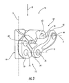
- the fixed member 13 (which can be seen more clearly in figs. 3 and 4 , separate from the rest of the mechanism) comprises a cylindrical surface 61 for attachment to a portion of the seat-tube of the bicycle frame of a shape matching the cylindrical surface 61 (braze-on attachment); the cylindrical surface 61 extends around a central axis Y.
- the fixed member 13 then comprises, at the first axis A, a first forked structure 62 that embraces the first connecting rod 14.
- the first forked structure 62 is formed from a first flange 63 facing a second flange 64, provided with respective holes 65 and 66 aligned along the axis A; a pin 68 is inserted in the holes 65 and 66 and in a hole 69 aligned with them formed in the first connecting rod 14, so as to provide the articulated coupling between the fixed member 13 and the connecting rod 14.
- the fixed member 13 also comprises, at the third axis C, a second forked structure 72 that embraces the second connecting rod 15.
- the second forked structure 72 is formed from a first flange 73 facing a second flange 74, provided with respective holes 75 and 76 aligned along the axis C; a pin 78 is inserted in the holes 75 and 76 and in a hole aligned with them formed in the second connecting rod 15, in particular in its upper portion 34, so as to provide the articulated coupling between the fixed member 13 and the connecting rod 14.
- a through hole 60 facing into the cylindrical surface 61 is formed, to receive an attachment screw (not shown) for the connection to the seat of the seat-tube.
- the first forked structure 62 with its flanges 63 and 64 laterally embraces the first connecting rod 14 and supports the articulation pin 68 at the ends thereof.
- the stress is transmitted from the actuation arm 25 into the articulation area at the pin 68.
- the stress is distributed in the central area of the pin 68, located between the two flanges 63 and 64, and not mainly at one end, like in deraille of the prior art.
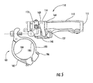
- Figures 5 and 6 show a view from above of a variant of a derailleur 110, which differs from the derailleur 10 described above for the method of connection to the seat-tube, through a clamp attachment instead of in a seat with cylindrical surface.
- the derailleur 110 is totally similar to the derailleur 10 and shall not be described in detail hereafter apart from what is different therefrom.
- the parts of the derailleur 110 that correspond to the derailleur 10 are indicated with the same reference numerals increased by 100.
- a clamp adapter element 181 is applied (in particular screwed) to the fixed member 113 to connect the derailleur 110 to the seat-tube of the bicycle.
- the clamp adapter element 181 (of the per se known type) comprises two semi-circular portions 182, 183, articulated together, to allow them to open out, with respective circular surfaces 184, 185 that are clamped on the frame by a bolt 186 when the derailleur 110 is in mounted configuration.
- Fig. 7 shows a variant 213 of the fixed member of the derailleur that differs from the fixed member 113 in that it comprises two semi-circular portions 282, 283, articulated together, to allow them to open out, with respective circular surfaces 284, 285 that are clamped on the frame by a bolt 286 when the derailleur is in mounted configuration.
- the fixed member 213 is formed in one piece with the semi-circular portion 283.
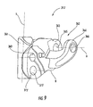
- Figure 8 shows a perspective view of another variant of the derailleur 310, which differs from the derailleur 10 described above for the different embodiment of the fixed member 313', shown in greater detail in figure 9 .
- the derailleur 310 is totally similar to the derailleur 10 and shall not be described in detail hereafter apart from what is different therefrom.
- the parts of the derailleur 310 that correspond to the derailleur 10 are indicated with the same reference numerals increased by 300.
- the fixed member 313' is similar to the fixed member 13, except for in the area of the articulation axis C. In this area, indeed, the fixed member 313' comprises a flange 373' provided with a hole 375' for receiving a pin 378' arranged canti-levered with respect to the flange 373'.
- the fixed member 313' does not have the flange facing the flange 373' and the second connecting rod 315 is connected to the fixed member 313' canti-levered, on the pin 378', as can be seen in fig. 8 .
- the pin in the couplings between a forked structure and a connecting rod, it is possible for the pin to be formed in one piece with the connecting rod and for the flanges of the forked structure to consequently be in two pieces, so as to be able to be mounted on the pin; or else, it is also possible for the pin - possibly in two pieces - to be formed in one piece with the flanges and for the connecting rod to consequently be made in two pieces, so as to be able to be mounted on the pin.
- the thrusting area of the actuation arm of the first connecting rod can consist of a toothed sector engaged with a driving screw.
Landscapes
- Engineering & Computer Science (AREA)
- Chemical & Material Sciences (AREA)
- Combustion & Propulsion (AREA)
- Transportation (AREA)
- Mechanical Engineering (AREA)
- Steering Devices For Bicycles And Motorcycles (AREA)
- Transmission Devices (AREA)
- Tires In General (AREA)
- Pivots And Pivotal Connections (AREA)
Applications Claiming Priority (1)
| Application Number | Priority Date | Filing Date | Title |
|---|---|---|---|
| IT000883A ITMI20070883A1 (it) | 2007-05-03 | 2007-05-03 | Deragliatore anteriore per una bicicletta |
Publications (3)
| Publication Number | Publication Date |
|---|---|
| EP1990268A2 true EP1990268A2 (fr) | 2008-11-12 |
| EP1990268A3 EP1990268A3 (fr) | 2010-06-23 |
| EP1990268B1 EP1990268B1 (fr) | 2016-11-02 |
Family
ID=38626711
Family Applications (1)
| Application Number | Title | Priority Date | Filing Date |
|---|---|---|---|
| EP08005645.0A Not-in-force EP1990268B1 (fr) | 2007-05-03 | 2008-03-26 | Dérailleur avant pour bicyclette |
Country Status (6)
| Country | Link |
|---|---|
| US (1) | US8029396B2 (fr) |
| EP (1) | EP1990268B1 (fr) |
| JP (1) | JP2008273512A (fr) |
| CN (1) | CN101311063A (fr) |
| IT (1) | ITMI20070883A1 (fr) |
| TW (1) | TW200902379A (fr) |
Families Citing this family (13)
| Publication number | Priority date | Publication date | Assignee | Title |
|---|---|---|---|---|
| TWM375657U (en) | 2009-10-15 | 2010-03-11 | Shimano Kk | Fixed member of front derailleur |
| US9327792B2 (en) | 2011-01-28 | 2016-05-03 | Paha Designs, Llc | Gear transmission and derailleur system |
| US9033833B2 (en) | 2011-01-28 | 2015-05-19 | Paha Designs, Llc | Gear transmission and derailleur system |
| US10207772B2 (en) | 2011-01-28 | 2019-02-19 | Paha Designs, Llc | Gear transmission and derailleur system |
| US20140265220A1 (en) * | 2013-03-15 | 2014-09-18 | Zike, Llc | Low Profile Derailleur For Chain Driven Personal Vehicle |
| JP2015016792A (ja) * | 2013-07-11 | 2015-01-29 | 株式会社シマノ | フロントディレーラ |
| US9248885B2 (en) * | 2013-09-30 | 2016-02-02 | Shimano Inc. | Derailleur |
| ITMI20131641A1 (it) * | 2013-10-04 | 2015-04-05 | Campagnolo Srl | Dispositivo di arresto dello spostamento laterale di una catena di bicicletta |
| ITUA201696738U1 (it) * | 2016-05-04 | 2017-11-04 | Campagnolo Srl | Dispositivo attuatore per un cambio di bicicletta e relativo cambio di bicicletta. |
| TWI729154B (zh) * | 2016-07-05 | 2021-06-01 | 義大利商坎帕克諾羅公司 | 自行車的前變速器的控制線的致動裝置 |
| IT201700015324A1 (it) * | 2017-02-13 | 2018-08-13 | Campagnolo Srl | Deragliatore anteriore per bicicletta |
| IT201700015349A1 (it) * | 2017-02-13 | 2018-08-13 | Campagnolo Srl | Dispositivo di azionamento del deragliatore anteriore di una bicicletta |
| US11787506B2 (en) * | 2021-03-30 | 2023-10-17 | Shimano Inc. | Derailleur for human-powered vehicle |
Citations (1)
| Publication number | Priority date | Publication date | Assignee | Title |
|---|---|---|---|---|
| US7081058B2 (en) | 2003-02-12 | 2006-07-25 | Shimano Inc. | Bicycle front derailleur |
Family Cites Families (21)
| Publication number | Priority date | Publication date | Assignee | Title |
|---|---|---|---|---|
| FR2294079A1 (fr) * | 1974-12-12 | 1976-07-09 | Shimano Industrial Co | Derailleur avant pour une bicyclette |
| US4226130A (en) * | 1977-09-05 | 1980-10-07 | Shimano Industrial Company, Limited | Front derailleur for a bicycle |
| FR2415037B1 (fr) * | 1978-01-18 | 1985-12-13 | Bloy Georges | Derailleur de pedalier pour cycles |
| JPS5514631Y2 (fr) * | 1978-02-24 | 1980-04-03 | ||
| US4259873A (en) * | 1978-06-02 | 1981-04-07 | Shimano Industrial Company Limited | Derailleur |
| JPS609120Y2 (ja) * | 1979-08-15 | 1985-04-01 | 株式会社シマノ | 自転車用フロントデイレ−ラ− |
| JPH0829743B2 (ja) * | 1986-04-11 | 1996-03-27 | 島野工業株式会社 | 自転車用フロントデイレ−ラ− |
| JPH0322071Y2 (fr) * | 1986-07-10 | 1991-05-14 | ||
| JPH0352297U (fr) * | 1989-09-28 | 1991-05-21 | ||
| US5312301A (en) * | 1991-11-29 | 1994-05-17 | Maeda Industries, Ltd. | Bicycle front derailleur |
| US5389043A (en) * | 1994-05-09 | 1995-02-14 | Hsu; Yi-Hsung | Bicycle top-pull front derailleur |
| DE9410177U1 (de) * | 1994-05-10 | 1994-11-10 | Hsu, Yi Hsung, San Chung, Taipeh | Von oben zu betätigende vordere Fahrradkettenschaltung |
| US6234927B1 (en) * | 1999-02-26 | 2001-05-22 | Shimano (Singapore) Pte., Ltd. | Front derailleur for a bicycle |
| US6629903B1 (en) * | 2000-04-17 | 2003-10-07 | Shimano Inc. | Bicycle derailleur |
| US6986723B2 (en) * | 2000-09-15 | 2006-01-17 | Campagnolo S.R.L. | Front bicycle derailleur |
| IT1320646B1 (it) * | 2000-09-15 | 2003-12-10 | Campagnolo Srl | Forcella di deragliatore anteriore di bicicletta, e deragliatorecomprendente tale forcella. |
| US7014584B2 (en) * | 2002-12-27 | 2006-03-21 | Shimano Inc. | Top pull type front derailleur |
| US7331890B2 (en) * | 2004-02-26 | 2008-02-19 | Shimano Inc. | Motorized front derailleur mounting member |
| US7306531B2 (en) * | 2004-04-23 | 2007-12-11 | Shimano Inc. | Electric bicycle derailleur |
| US7722486B2 (en) * | 2005-12-14 | 2010-05-25 | Shimano Inc. | Top/bottom pull bicycle front derailleur |
| USD555050S1 (en) * | 2005-12-16 | 2007-11-13 | Shimano Inc. | Front derailleur for a bicycle |
-
2007
- 2007-05-03 IT IT000883A patent/ITMI20070883A1/it unknown
-
2008
- 2008-03-26 EP EP08005645.0A patent/EP1990268B1/fr not_active Not-in-force
- 2008-04-14 TW TW097113514A patent/TW200902379A/zh unknown
- 2008-05-01 JP JP2008120043A patent/JP2008273512A/ja active Pending
- 2008-05-01 US US12/113,713 patent/US8029396B2/en active Active
- 2008-05-04 CN CNA2008100928630A patent/CN101311063A/zh active Pending
Patent Citations (1)
| Publication number | Priority date | Publication date | Assignee | Title |
|---|---|---|---|---|
| US7081058B2 (en) | 2003-02-12 | 2006-07-25 | Shimano Inc. | Bicycle front derailleur |
Also Published As
| Publication number | Publication date |
|---|---|
| TW200902379A (en) | 2009-01-16 |
| ITMI20070883A1 (it) | 2008-11-04 |
| EP1990268B1 (fr) | 2016-11-02 |
| JP2008273512A (ja) | 2008-11-13 |
| CN101311063A (zh) | 2008-11-26 |
| US20080274845A1 (en) | 2008-11-06 |
| US8029396B2 (en) | 2011-10-04 |
| EP1990268A3 (fr) | 2010-06-23 |
Similar Documents
| Publication | Publication Date | Title |
|---|---|---|
| EP1990268B1 (fr) | Dérailleur avant pour bicyclette | |
| CN100560425C (zh) | 前拨链器及其安装件 | |
| EP1447317B2 (fr) | Dérailleur avant pour bicyclette | |
| US10065705B2 (en) | Bicycle derailleur | |
| US20160068225A1 (en) | Bicycle front derailleur | |
| CN109250029B (zh) | 自行车后变速器 | |
| US8267820B2 (en) | Bicycle chain tensioner | |
| WO2010033212A1 (fr) | Dérailleur avant à six maillons | |
| US20090137354A1 (en) | Bicycle rear derailleur | |
| EP2572972A1 (fr) | Dérailleur avant dýune bicyclette | |
| US9616970B2 (en) | Bicycle derailleur | |
| CN1982154B (zh) | 顶部/底部牵拉型自行车前拨链器 | |
| CN100542881C (zh) | 变速齿轮传动机构及将其连接到自行车上的装置 | |
| TWI323234B (en) | Bicycle rear derailleur | |
| US10822051B2 (en) | Bicycle derailleur | |
| EP2520480B1 (fr) | Corps de dérailleur avant de bicyclette et dispositif pour l'installation réglable d'un tel corps de dérailleur sur un tube de cadre de bicyclette | |
| US4801287A (en) | Rear derailer for bicycle gears | |
| EP3366566B1 (fr) | Dérailleur de bicyclette | |
| EP1721822B1 (fr) | Dérailleur avant avec fixation variable à un cadre de bicyclette | |
| US8444514B2 (en) | Front derailleur chain detachment prevention member | |
| EP1790564A1 (fr) | Dispositif de commande pour dérailleur de bicyclette | |
| EP1568596B1 (fr) | Actionneur motorisé pour dérailleur de bicyclette, avec mécanisme de commande de friction | |
| CN108516045A (zh) | 用于自行车的前变速器 | |
| EP2116465A1 (fr) | Panneau à fixer sur le support d'un récipient | |
| WO2024256551A1 (fr) | Dérailleur arrière avec tendeur à double bras |
Legal Events
| Date | Code | Title | Description |
|---|---|---|---|
| PUAI | Public reference made under article 153(3) epc to a published international application that has entered the european phase |
Free format text: ORIGINAL CODE: 0009012 |
|
| AK | Designated contracting states |
Kind code of ref document: A2 Designated state(s): AT BE BG CH CY CZ DE DK EE ES FI FR GB GR HR HU IE IS IT LI LT LU LV MC MT NL NO PL PT RO SE SI SK TR |
|
| AX | Request for extension of the european patent |
Extension state: AL BA MK RS |
|
| PUAL | Search report despatched |
Free format text: ORIGINAL CODE: 0009013 |
|
| AK | Designated contracting states |
Kind code of ref document: A3 Designated state(s): AT BE BG CH CY CZ DE DK EE ES FI FR GB GR HR HU IE IS IT LI LT LU LV MC MT NL NO PL PT RO SE SI SK TR |
|
| AX | Request for extension of the european patent |
Extension state: AL BA MK RS |
|
| 17P | Request for examination filed |
Effective date: 20101217 |
|
| AKX | Designation fees paid |
Designated state(s): AT BE BG CH CY CZ DE DK EE ES FI FR GB GR HR HU IE IS IT LI LT LU LV MC MT NL NO PL PT RO SE SI SK TR |
|
| GRAP | Despatch of communication of intention to grant a patent |
Free format text: ORIGINAL CODE: EPIDOSNIGR1 |
|
| INTG | Intention to grant announced |
Effective date: 20160114 |
|
| GRAS | Grant fee paid |
Free format text: ORIGINAL CODE: EPIDOSNIGR3 |
|
| GRAP | Despatch of communication of intention to grant a patent |
Free format text: ORIGINAL CODE: EPIDOSNIGR1 |
|
| INTG | Intention to grant announced |
Effective date: 20160729 |
|
| GRAA | (expected) grant |
Free format text: ORIGINAL CODE: 0009210 |
|
| AK | Designated contracting states |
Kind code of ref document: B1 Designated state(s): AT BE BG CH CY CZ DE DK EE ES FI FR GB GR HR HU IE IS IT LI LT LU LV MC MT NL NO PL PT RO SE SI SK TR |
|
| REG | Reference to a national code |
Ref country code: GB Ref legal event code: FG4D |
|
| REG | Reference to a national code |
Ref country code: AT Ref legal event code: REF Ref document number: 841531 Country of ref document: AT Kind code of ref document: T Effective date: 20161115 Ref country code: CH Ref legal event code: EP |
|
| REG | Reference to a national code |
Ref country code: IE Ref legal event code: FG4D |
|
| REG | Reference to a national code |
Ref country code: DE Ref legal event code: R096 Ref document number: 602008047124 Country of ref document: DE |
|
| PG25 | Lapsed in a contracting state [announced via postgrant information from national office to epo] |
Ref country code: LV Free format text: LAPSE BECAUSE OF FAILURE TO SUBMIT A TRANSLATION OF THE DESCRIPTION OR TO PAY THE FEE WITHIN THE PRESCRIBED TIME-LIMIT Effective date: 20161102 |
|
| REG | Reference to a national code |
Ref country code: NL Ref legal event code: MP Effective date: 20161102 |
|
| REG | Reference to a national code |
Ref country code: LT Ref legal event code: MG4D |
|
| REG | Reference to a national code |
Ref country code: AT Ref legal event code: MK05 Ref document number: 841531 Country of ref document: AT Kind code of ref document: T Effective date: 20161102 |
|
| REG | Reference to a national code |
Ref country code: FR Ref legal event code: PLFP Year of fee payment: 10 |
|
| PG25 | Lapsed in a contracting state [announced via postgrant information from national office to epo] |
Ref country code: NO Free format text: LAPSE BECAUSE OF FAILURE TO SUBMIT A TRANSLATION OF THE DESCRIPTION OR TO PAY THE FEE WITHIN THE PRESCRIBED TIME-LIMIT Effective date: 20170202 Ref country code: GR Free format text: LAPSE BECAUSE OF FAILURE TO SUBMIT A TRANSLATION OF THE DESCRIPTION OR TO PAY THE FEE WITHIN THE PRESCRIBED TIME-LIMIT Effective date: 20170203 Ref country code: SE Free format text: LAPSE BECAUSE OF FAILURE TO SUBMIT A TRANSLATION OF THE DESCRIPTION OR TO PAY THE FEE WITHIN THE PRESCRIBED TIME-LIMIT Effective date: 20161102 Ref country code: LT Free format text: LAPSE BECAUSE OF FAILURE TO SUBMIT A TRANSLATION OF THE DESCRIPTION OR TO PAY THE FEE WITHIN THE PRESCRIBED TIME-LIMIT Effective date: 20161102 Ref country code: NL Free format text: LAPSE BECAUSE OF FAILURE TO SUBMIT A TRANSLATION OF THE DESCRIPTION OR TO PAY THE FEE WITHIN THE PRESCRIBED TIME-LIMIT Effective date: 20161102 |
|
| PG25 | Lapsed in a contracting state [announced via postgrant information from national office to epo] |
Ref country code: AT Free format text: LAPSE BECAUSE OF FAILURE TO SUBMIT A TRANSLATION OF THE DESCRIPTION OR TO PAY THE FEE WITHIN THE PRESCRIBED TIME-LIMIT Effective date: 20161102 Ref country code: PL Free format text: LAPSE BECAUSE OF FAILURE TO SUBMIT A TRANSLATION OF THE DESCRIPTION OR TO PAY THE FEE WITHIN THE PRESCRIBED TIME-LIMIT Effective date: 20161102 Ref country code: PT Free format text: LAPSE BECAUSE OF FAILURE TO SUBMIT A TRANSLATION OF THE DESCRIPTION OR TO PAY THE FEE WITHIN THE PRESCRIBED TIME-LIMIT Effective date: 20170302 Ref country code: FI Free format text: LAPSE BECAUSE OF FAILURE TO SUBMIT A TRANSLATION OF THE DESCRIPTION OR TO PAY THE FEE WITHIN THE PRESCRIBED TIME-LIMIT Effective date: 20161102 Ref country code: IS Free format text: LAPSE BECAUSE OF FAILURE TO SUBMIT A TRANSLATION OF THE DESCRIPTION OR TO PAY THE FEE WITHIN THE PRESCRIBED TIME-LIMIT Effective date: 20170302 Ref country code: ES Free format text: LAPSE BECAUSE OF FAILURE TO SUBMIT A TRANSLATION OF THE DESCRIPTION OR TO PAY THE FEE WITHIN THE PRESCRIBED TIME-LIMIT Effective date: 20161102 Ref country code: HR Free format text: LAPSE BECAUSE OF FAILURE TO SUBMIT A TRANSLATION OF THE DESCRIPTION OR TO PAY THE FEE WITHIN THE PRESCRIBED TIME-LIMIT Effective date: 20161102 |
|
| PG25 | Lapsed in a contracting state [announced via postgrant information from national office to epo] |
Ref country code: SK Free format text: LAPSE BECAUSE OF FAILURE TO SUBMIT A TRANSLATION OF THE DESCRIPTION OR TO PAY THE FEE WITHIN THE PRESCRIBED TIME-LIMIT Effective date: 20161102 Ref country code: EE Free format text: LAPSE BECAUSE OF FAILURE TO SUBMIT A TRANSLATION OF THE DESCRIPTION OR TO PAY THE FEE WITHIN THE PRESCRIBED TIME-LIMIT Effective date: 20161102 Ref country code: CZ Free format text: LAPSE BECAUSE OF FAILURE TO SUBMIT A TRANSLATION OF THE DESCRIPTION OR TO PAY THE FEE WITHIN THE PRESCRIBED TIME-LIMIT Effective date: 20161102 Ref country code: DK Free format text: LAPSE BECAUSE OF FAILURE TO SUBMIT A TRANSLATION OF THE DESCRIPTION OR TO PAY THE FEE WITHIN THE PRESCRIBED TIME-LIMIT Effective date: 20161102 Ref country code: RO Free format text: LAPSE BECAUSE OF FAILURE TO SUBMIT A TRANSLATION OF THE DESCRIPTION OR TO PAY THE FEE WITHIN THE PRESCRIBED TIME-LIMIT Effective date: 20161102 |
|
| REG | Reference to a national code |
Ref country code: DE Ref legal event code: R097 Ref document number: 602008047124 Country of ref document: DE |
|
| PG25 | Lapsed in a contracting state [announced via postgrant information from national office to epo] |
Ref country code: BE Free format text: LAPSE BECAUSE OF FAILURE TO SUBMIT A TRANSLATION OF THE DESCRIPTION OR TO PAY THE FEE WITHIN THE PRESCRIBED TIME-LIMIT Effective date: 20161102 Ref country code: BG Free format text: LAPSE BECAUSE OF FAILURE TO SUBMIT A TRANSLATION OF THE DESCRIPTION OR TO PAY THE FEE WITHIN THE PRESCRIBED TIME-LIMIT Effective date: 20170202 |
|
| PLBE | No opposition filed within time limit |
Free format text: ORIGINAL CODE: 0009261 |
|
| STAA | Information on the status of an ep patent application or granted ep patent |
Free format text: STATUS: NO OPPOSITION FILED WITHIN TIME LIMIT |
|
| 26N | No opposition filed |
Effective date: 20170803 |
|
| REG | Reference to a national code |
Ref country code: CH Ref legal event code: PL |
|
| GBPC | Gb: european patent ceased through non-payment of renewal fee |
Effective date: 20170326 |
|
| PG25 | Lapsed in a contracting state [announced via postgrant information from national office to epo] |
Ref country code: MC Free format text: LAPSE BECAUSE OF FAILURE TO SUBMIT A TRANSLATION OF THE DESCRIPTION OR TO PAY THE FEE WITHIN THE PRESCRIBED TIME-LIMIT Effective date: 20161102 Ref country code: SI Free format text: LAPSE BECAUSE OF FAILURE TO SUBMIT A TRANSLATION OF THE DESCRIPTION OR TO PAY THE FEE WITHIN THE PRESCRIBED TIME-LIMIT Effective date: 20161102 |
|
| REG | Reference to a national code |
Ref country code: IE Ref legal event code: MM4A |
|
| PG25 | Lapsed in a contracting state [announced via postgrant information from national office to epo] |
Ref country code: LU Free format text: LAPSE BECAUSE OF NON-PAYMENT OF DUE FEES Effective date: 20170326 |
|
| PG25 | Lapsed in a contracting state [announced via postgrant information from national office to epo] |
Ref country code: LI Free format text: LAPSE BECAUSE OF NON-PAYMENT OF DUE FEES Effective date: 20170331 Ref country code: GB Free format text: LAPSE BECAUSE OF NON-PAYMENT OF DUE FEES Effective date: 20170326 Ref country code: CH Free format text: LAPSE BECAUSE OF NON-PAYMENT OF DUE FEES Effective date: 20170331 Ref country code: IE Free format text: LAPSE BECAUSE OF NON-PAYMENT OF DUE FEES Effective date: 20170326 |
|
| REG | Reference to a national code |
Ref country code: FR Ref legal event code: PLFP Year of fee payment: 11 |
|
| PG25 | Lapsed in a contracting state [announced via postgrant information from national office to epo] |
Ref country code: MT Free format text: LAPSE BECAUSE OF NON-PAYMENT OF DUE FEES Effective date: 20170326 |
|
| PG25 | Lapsed in a contracting state [announced via postgrant information from national office to epo] |
Ref country code: HU Free format text: LAPSE BECAUSE OF FAILURE TO SUBMIT A TRANSLATION OF THE DESCRIPTION OR TO PAY THE FEE WITHIN THE PRESCRIBED TIME-LIMIT; INVALID AB INITIO Effective date: 20080326 |
|
| PG25 | Lapsed in a contracting state [announced via postgrant information from national office to epo] |
Ref country code: CY Free format text: LAPSE BECAUSE OF NON-PAYMENT OF DUE FEES Effective date: 20161102 |
|
| PG25 | Lapsed in a contracting state [announced via postgrant information from national office to epo] |
Ref country code: TR Free format text: LAPSE BECAUSE OF FAILURE TO SUBMIT A TRANSLATION OF THE DESCRIPTION OR TO PAY THE FEE WITHIN THE PRESCRIBED TIME-LIMIT Effective date: 20161102 |
|
| PGFP | Annual fee paid to national office [announced via postgrant information from national office to epo] |
Ref country code: FR Payment date: 20230327 Year of fee payment: 16 |
|
| PGFP | Annual fee paid to national office [announced via postgrant information from national office to epo] |
Ref country code: IT Payment date: 20230321 Year of fee payment: 16 Ref country code: DE Payment date: 20230329 Year of fee payment: 16 |
|
| P01 | Opt-out of the competence of the unified patent court (upc) registered |
Effective date: 20230515 |
|
| REG | Reference to a national code |
Ref country code: DE Ref legal event code: R119 Ref document number: 602008047124 Country of ref document: DE |
|
| PG25 | Lapsed in a contracting state [announced via postgrant information from national office to epo] |
Ref country code: DE Free format text: LAPSE BECAUSE OF NON-PAYMENT OF DUE FEES Effective date: 20241001 |
|
| PG25 | Lapsed in a contracting state [announced via postgrant information from national office to epo] |
Ref country code: FR Free format text: LAPSE BECAUSE OF NON-PAYMENT OF DUE FEES Effective date: 20240331 |
|
| PG25 | Lapsed in a contracting state [announced via postgrant information from national office to epo] |
Ref country code: FR Free format text: LAPSE BECAUSE OF NON-PAYMENT OF DUE FEES Effective date: 20240331 Ref country code: DE Free format text: LAPSE BECAUSE OF NON-PAYMENT OF DUE FEES Effective date: 20241001 |
|
| PG25 | Lapsed in a contracting state [announced via postgrant information from national office to epo] |
Ref country code: IT Free format text: LAPSE BECAUSE OF NON-PAYMENT OF DUE FEES Effective date: 20240326 |