EP1990286A1 - Behälter mit Ausgabevorrichtung - Google Patents
Behälter mit Ausgabevorrichtung Download PDFInfo
- Publication number
- EP1990286A1 EP1990286A1 EP07009275A EP07009275A EP1990286A1 EP 1990286 A1 EP1990286 A1 EP 1990286A1 EP 07009275 A EP07009275 A EP 07009275A EP 07009275 A EP07009275 A EP 07009275A EP 1990286 A1 EP1990286 A1 EP 1990286A1
- Authority
- EP
- European Patent Office
- Prior art keywords
- container
- outlet
- barrier wall
- dispensing device
- top portion
- Prior art date
- Legal status (The legal status is an assumption and is not a legal conclusion. Google has not performed a legal analysis and makes no representation as to the accuracy of the status listed.)
- Withdrawn
Links
- 230000004888 barrier function Effects 0.000 claims abstract description 89
- 239000000463 material Substances 0.000 claims abstract description 43
- 238000003780 insertion Methods 0.000 claims abstract description 13
- 230000037431 insertion Effects 0.000 claims abstract description 13
- 230000007704 transition Effects 0.000 claims description 3
- 239000011888 foil Substances 0.000 claims description 2
- 239000008187 granular material Substances 0.000 description 10
- 235000021539 instant coffee Nutrition 0.000 description 8
- 235000013353 coffee beverage Nutrition 0.000 description 5
- 239000000843 powder Substances 0.000 description 4
- 239000000047 product Substances 0.000 description 4
- 241001122767 Theaceae Species 0.000 description 3
- 239000003599 detergent Substances 0.000 description 3
- 235000020344 instant tea Nutrition 0.000 description 3
- 235000000346 sugar Nutrition 0.000 description 3
- 230000006866 deterioration Effects 0.000 description 2
- 238000000034 method Methods 0.000 description 2
- QVGXLLKOCUKJST-UHFFFAOYSA-N atomic oxygen Chemical compound [O] QVGXLLKOCUKJST-UHFFFAOYSA-N 0.000 description 1
- 230000008859 change Effects 0.000 description 1
- 239000012467 final product Substances 0.000 description 1
- 230000007246 mechanism Effects 0.000 description 1
- 230000003647 oxidation Effects 0.000 description 1
- 238000007254 oxidation reaction Methods 0.000 description 1
- 229910052760 oxygen Inorganic materials 0.000 description 1
- 239000001301 oxygen Substances 0.000 description 1
- 230000002093 peripheral effect Effects 0.000 description 1
- 230000001681 protective effect Effects 0.000 description 1
- 230000009467 reduction Effects 0.000 description 1
- 230000000717 retained effect Effects 0.000 description 1
- 239000002699 waste material Substances 0.000 description 1
Images



Classifications
-
- G—PHYSICS
- G01—MEASURING; TESTING
- G01F—MEASURING VOLUME, VOLUME FLOW, MASS FLOW OR LIQUID LEVEL; METERING BY VOLUME
- G01F11/00—Apparatus requiring external operation adapted at each repeated and identical operation to measure and separate a predetermined volume of fluid or fluent solid material from a supply or container, without regard to weight, and to deliver it
- G01F11/10—Apparatus requiring external operation adapted at each repeated and identical operation to measure and separate a predetermined volume of fluid or fluent solid material from a supply or container, without regard to weight, and to deliver it with measuring chambers moved during operation
- G01F11/26—Apparatus requiring external operation adapted at each repeated and identical operation to measure and separate a predetermined volume of fluid or fluent solid material from a supply or container, without regard to weight, and to deliver it with measuring chambers moved during operation wherein the measuring chamber is filled and emptied by tilting or inverting the supply vessel, e.g. bottle-emptying apparatus
- G01F11/261—Apparatus requiring external operation adapted at each repeated and identical operation to measure and separate a predetermined volume of fluid or fluent solid material from a supply or container, without regard to weight, and to deliver it with measuring chambers moved during operation wherein the measuring chamber is filled and emptied by tilting or inverting the supply vessel, e.g. bottle-emptying apparatus for fluent solid material
-
- B—PERFORMING OPERATIONS; TRANSPORTING
- B65—CONVEYING; PACKING; STORING; HANDLING THIN OR FILAMENTARY MATERIAL
- B65D—CONTAINERS FOR STORAGE OR TRANSPORT OF ARTICLES OR MATERIALS, e.g. BAGS, BARRELS, BOTTLES, BOXES, CANS, CARTONS, CRATES, DRUMS, JARS, TANKS, HOPPERS, FORWARDING CONTAINERS; ACCESSORIES, CLOSURES, OR FITTINGS THEREFOR; PACKAGING ELEMENTS; PACKAGES
- B65D25/00—Details of other kinds or types of rigid or semi-rigid containers
- B65D25/38—Devices for discharging contents
- B65D25/52—Devices for discharging successive articles or portions of contents
-
- B—PERFORMING OPERATIONS; TRANSPORTING
- B65—CONVEYING; PACKING; STORING; HANDLING THIN OR FILAMENTARY MATERIAL
- B65D—CONTAINERS FOR STORAGE OR TRANSPORT OF ARTICLES OR MATERIALS, e.g. BAGS, BARRELS, BOTTLES, BOXES, CANS, CARTONS, CRATES, DRUMS, JARS, TANKS, HOPPERS, FORWARDING CONTAINERS; ACCESSORIES, CLOSURES, OR FITTINGS THEREFOR; PACKAGING ELEMENTS; PACKAGES
- B65D83/00—Containers or packages with special means for dispensing contents
- B65D83/06—Containers or packages with special means for dispensing contents for dispensing powdered or granular material
Definitions
- the present invention relates to a container for containing granular material such as ground coffee, freeze-dried instant coffee or tea, sugar, detergent powder, and the like, and including a dispensing device for releasable insertion into the outlet of the container and for dispensing the granular product.
- granular material such as ground coffee, freeze-dried instant coffee or tea, sugar, detergent powder, and the like
- a storage container and a dispensing device are known in the art, but all such known combinations are complicated as regards use and/or constructive elements. Furthermore, the dispensing device is often provided as an integral part of the container, which may not be desirable, neither from the point of view of the manufacturer of the container nor from the point of view of the user.
- a simple and inexpensive dispensing device for a granular product which can be inserted into and if desired removed from a storage container that may be operated by any person and protects the contents of the container against deterioration by loss of aroma or oxidation by limiting the contact with the atmosphere.
- the batch-wise dispensing should also be precise and uniform (reproducible) so that it is ensured that the desired total amount of product dispensed is achieved without having to resort to further measuring actions. It is furthermore important that the dispensing device can be inserted into and released from the storage container in an easy and intuitively correct manner and also that the dispensing device, when inserted into the storage container, is reliably retained in the container.
- a dispensing device for batch dispensing granular material such as ground coffee, freeze-dried instant coffee or tea, sugar
- which dispensing device is designed for releasable insertion into an outlet of a hand-held container, for instance into the neck portion of a jar for such a container.
- the dispensing device basically comprises a top portion subdividing the cross sectional area of an outlet of the container into a closed portion, through which material present in the container cannot pass, and an open portion, through which material present in the container can pass, said closed and open portions being divided by an edge, where the top portion is provided with side portions for releasable insertion into the outlet of the container, where the side portions opposite the top portion comprise radially outwardly extending, resilient retainment portions formed for releasable engagement with the outlet of the container or regions of the container adjacent the outlet of the container, the outer shape of the retainment portions substantially corresponding to the corresponding portions of the inner surface of the outlet, into which the dispensing device is to be inserted.
- these retainment portions are shaped as a skirt, tapering radially outwards from the corresponding side portion in the direction away from the top portion.
- the retainment portions are in the following briefly referred to as "skirt portions”.
- Said edge is provided with an outlet barrier wall extending from the top portion into the outlet of the container, the dispensing device being furthermore provided with an inlet barrier wall inclined relative to the outlet barrier wall, one edge portion of the inlet barrier wall being formed for contact with an inner wall portion of the outlet of the container when the device is placed in the outlet of the container, and an opposing edge portion of the inlet barrier wall defining an opening between the top portion and said opposing edge portion of the inlet barrier wall, an opening being furthermore defined between said inlet barrier wall and said outlet barrier wall, the inlet barrier wall, the top portion and the outlet barrier wall when the device is placed in the outlet of the container, thereby defining a passageway through which material can pass from the interior of the container through the passageway and out through the outlet of the container.
- a specific embodiment of a dispensing device according to the invention is of a generally cylindrical shape formed for insertion into a corresponding cylindrical neck portion of a jar for containing ground coffee, freeze-dried instant coffee, etc. This specific embodiment will be described in more detail in the detailed description of the invention.
- An alternative embodiment of the invention could be a box-shaped device formed for insertion into a corresponding box-shaped outlet portion of a container. A number of other alternative general shapes would also fall within the scope of the invention as defined by independent claim 1.
- the dimensions and relative orientations of various of the inner structural elements of the dispensing device according to the invention have been found to be important for dispensing a precise and reproducible amount of material through the dispensing device.
- Relative dimensions and orientations of structures of the dispensing device can be defined with reference to the longitudinal axis Z through the device perpendicular to the plane of the top portion of the device and with the direction of the axis away from the container.
- the Z co-ordinate of the surface of the top portion is set to zero.
- the above mentioned outlet barrier wall then extends a distance d1 from the top portion towards the interior of the container and terminates in an edge portion at the Z co-ordinate -d1.
- the inclined inlet barrier wall extends as mentioned from the inner surface of the outlet of the container and terminates at an opposing edge portion, the Z co-ordinate of which is -d2. It has been found that optimally d2 > d1, so that a clearance ⁇ between the Z co-ordinate levels -d1 and -d2 is attained. This feature is illustrated more clearly in the detailed description of the invention. Furthermore the angle of inclination ⁇ of the inlet barrier wall relative to the longitudinal axis Z can be optimised and determines (together with the extension along the Z axis of the side portions with associated skirt portions) the insertion depth of the dispensing device into the outlet of the container.
- outlet barrier wall in the following detailed description of the invention is shown as extending perpendicularly from the top portion of the dispensing device, the outlet barrier wall may also form an angle ⁇ relative to the Z axis, the angle ⁇ in the shown embodiment being specifically chosen to 0 degrees.
- the outlet barrier wall in the embodiment described in the detailed description of the invention is of a rectangular shape, as seen from a direction perpendicular to the Z-axis, other shapes of the outlet barrier wall may also be used and will fall within the scope of the present invention.
- a device for batch dispensing granular material such as ground coffee, freeze-dried instant coffee or tea, sugar, detergent powder, and the like from the container
- the container has a top portion and a bottom portion, the container being manually rotatable from an upright position with said top portion located above said bottom portion and an inverted position with said top portion located below said bottom portion, the dispensing device and said container together defining a passageway extending in a material flow direction from the container for allowing granular material to enter said passage from said container to a material outlet for allowing granular material to exit from said passageway
- a barrier chamber being defined in said passageway between said material inlet of the dispensing device and the material outlet by means of an inlet barrier wall and an outlet barrier wall, said inlet barrier wall defining an inlet barrier aperture configured and located so as to allow material to flow into said barrier chamber in said flow direction when said container is in said inverted position and so as to hinder said material
- an intuitively easily understandable and easily implementable pouring motion of the container will entail dispensing of substantially uniformly-sized batches of the granular material without having to access the interior of the container and without any substantial risk of spilling material.
- the correct dosage of material from the container can be ascertained, thereby improving the quality of the final product obtained from the material in the container and furthermore reducing the risk of overdosing and potential waste of material.
- the dispensing device according to the invention may thus also lead to economically advantageous results.
- the top portion is flush with the upper rim portion of the outlet of the container when the dispensing device is inserted in the container.
- the outer surface of the top portion may be covered by a protective foil, which is also attached to the rim portion of the outlet of the container in order to ensure a hermetically sealed closure of the container.
- FIG 1 there is shown a schematic perspective view, partly in cross section, of a first embodiment of the dispensing device according to the invention.
- the dispensing device can be releasably inserted into an outlet of a container, as shown in figures 6 , 7 , and 8 .
- the device comprises a top portion 6, which in the shown embodiment is substantially planar, although other surface shapes could also be used if desired.
- the top portion 6 subdivides the cross-sectional area of an outlet of the container into a closed portion 3, through which material present in the container cannot pass, and an open portion 4, through which material present in the container can pass.
- the boundary of the top portion in the shown embodiment comprises a circular peripheral portion 15 corresponding in shape to a circular (cylindrical) outlet of a container, for instance the neck 2 of the jar 1 shown in figures 6 , 7 and 8 .
- the closed and open portions 3, 4 are divided by an edge portion 5.
- the top portion 6 is furthermore provided with side portions 7 for releasable insertion into the outlet of the container, and the side portions 7 comprise resilient skirt portions 8 for releasable engagement with the inner surface of the outlet of the container or regions of the inner surface of the container adjacent the outlet of the container.
- the skirt portions 8 can, due to their resiliency, be compressed during passage through the outlet portion of the container, whereby they can pass through the outlet of the container and, when the dispensing device is fully inserted into the container, the skirt portions expand following the expanding inner surface of the container.
- the edge 5 dividing the closed region 3 and the open region 4 is provided with an outlet barrier wall 9 extending from said top portion 6 into the outlet 2 of the container 1.
- the dispensing device is furthermore provided with an inlet barrier wall 10 inclined relative to the Z-axis and the outlet barrier wall 9.
- the plane of the inlet barrier wall 10 forms an angle ⁇ with the Z-axis.
- One edge portion 11 of the inlet barrier wall 10 is formed for contact with an inner wall portion of the outlet 2 of the container 1 when the device is placed in the outlet of the container, and an opposing edge portion 12 of the inlet barrier wall 10 defines a first opening 13 between the top portion 6 and said opposing edge portion 12 of the inlet barrier wall 10.
- the inlet barrier wall 10 in the shown embodiment comprises an elevated (in the direction of the Z-axis) edge portion 12, the inlet barrier wall 10 may alternatively form one smooth surface without the elevated portion 12.
- a second opening 14 is furthermore defined between said inlet barrier wall 10 and said outlet barrier wall 9.
- the output barrier wall 9 extends a distance d1 in the direction towards the container, terminating in a second edge portion 16 at the co-ordinate -d1.
- the inlet barrier wall 10 intersects the Z-axis at co-ordinate -d3, there being thus formed an opening 14 of height D between the lower edge portion 16 of the outlet barrier wall 9 and the corresponding surface portion of the inlet barrier wall 10.
- the inlet barrier wall 10, the top portion 6 and the outlet barrier wall 9 thereby define a passageway, through which material can pass from the interior of the container through the passageway and out through the outlet of the container.
- This passageway in the direction of flow of material out of the container comprises three chambers: an inlet chamber 18, a barrier chamber 19, and an outlet chamber 20, which may become even more apparent with reference to figure 7 described below.
- FIG 2 there is shown a side elevation, partly in cross section, of the embodiment of the dispensing device according to the invention shown in figure 1 .
- the parts of figure 2 shown in cross section (hatched) comprise the top portion 6 joined at the edge portion 5 with the outlet barrier wall 9, which extends in the direction towards the container (not shown), i.e. in the negative z-direction, a distance d1 to a terminating edge portion 16.
- the cross-sectional view furthermore comprises the inlet barrier wall 10 inclined an angle ⁇ relative to the longitudinal axis (Z-axis) of the dispensing device.
- the inlet barrier wall 10 terminates in an inclined end portion 11 formed to substantially correspond to the shape of the inner surface of the outlet of the container, which is located in the vicinity of the end portion 11 when the dispensing device is inserted into the outlet of the container.
- the inlet barrier wall 10 terminates at a second edge portion 12, located a distance d2 away from the upper surface of the top portion 6.
- d1 ⁇ d2 leaving a clearance ⁇ between the level of the edge 16 of the outlet barrier wall 9 and the edge 12 of the inlet barrier wall.
- a clearance has been found to be important to ensure that the amount of material dispensed by the dispensing device according to the invention will remain constant regardless of the reduction of amount of material in the container, as material is being dispensed from the container.
- the consistency of the material in the container will generally change from the initial upper portions of material in the container, where the material will have a relatively loose, granular structure, towards the lower portions of the material, where the material will become more dense or compressed, thus gradually assuming a more powdery consistency towards the lower portions of the material in the container.
- the presence of the clearance ⁇ has been found to be important for dispensing the same amount of material despite the gradually more dense consistency of the material towards the bottom of the container.
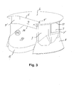
- Figure 3 shows a schematic, perspective view of the embodiment of the invention shown in figure 1 seen from a direction facing the outlet chamber 20 of the dispensing device.
- these may comprise one or more ribs 7' extending from the top portion 6 towards the skirt portion 8.
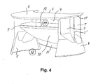
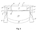
- a possible shape of the skirt portion 8 is shown in figure 3 (and figures 4 and 5 ), the skirt portion 8 being formed substantially as a section of a frustum of a cone. Other shapes may be appropriate and should ideally be chosen, taking into account the shape of the outlet portion and possibly adjacent portions of the specific container with which the dispensing device is to be used.
- Figure 3 furthermore illustrates a possible shape of the outlet barrier wall 9, where this wall is provided with curved transition regions 9' towards the inner surface of the side portions 7.
- the resulting outlet opening (see figure 8 ) from the container with the dispensing device inserted into the outlet will be of an approximately ellipsoidal shape.
- Figure 4 shows a schematic perspective view of the embodiment of the invention shown in figure 1 seen from a direction facing the inlet chamber 18 of the dispensing device. A portion of the barrier chamber 19 is also visible in figure 4 .
- Figure 5 shows a schematic front elevation of the embodiment shown in figure 1 , i.e. seen from a direction of the outlet chamber 20.
- the edge portions 17 of the top portion 6 may be inwardly inclined in order to fit a corresponding rim region of the outlet of the container, as for instance shown in figures 6 and 7 .
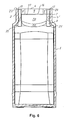
- Figure 6 shows a schematic cross-sectional side elevation of a container 1 with an embodiment of the dispensing device according to the invention inserted into the outlet (neck) portion 2 of the container, the container in this case being a jar typically used for freeze-dried instant coffee, etc.
- the dispensing device is shown in schematic front elevation, as in figure 5 .
- the skirt portions 8 extend radially outwardly due to their resiliency, thereby substantially following the outwardly extending transition region of the jar indicated by reference numeral 21 in figure 6 .
- Figure 7 shows a schematic cross-sectional front elevation of the jar 1 shown in figure 7 with an embodiment of the dispensing device according to the invention inserted into the neck portion 2 of the container.
- the dispensing device is shown in schematic, partly cross-sectional side elevation corresponding to figure 2 , thereby illustrating among other the inlet chamber 18, the barrier chamber 19, and the outlet chamber 20 formed by insertion of the dispensing device into the neck 2 of the jar 1.
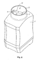
- Figure 8 shows a schematic perspective view of the jar 1 with the dispensing device inserted in the neck portion 2 of the jar in a state ready for dispensing material from the jar.
- the jar In use, when dispensing granular material from the interior of the jar, the jar is inverted so that the mouth of the jar and the top portion 6 of the device face generally downwards. In this inverted position of the jar, granular material will flow into the inlet chamber 18 and further into the barrier chamber 19 via the opening 13 (see figure 1 ) until it is stopped by the outlet barrier wall 9.
- the jar is then rotated so that the mouth of the jar and the top wall 6 are facing generally upwards.
- part of the granular material in the inlet chamber 18 will flow back into the jar, and the other part will be prevented from doing so by the inlet barrier wall 10. This other part will flow into the barrier chamber 19 and the outlet chamber 20.
- the granular material in the jar will thus be dispensed in substantially uniform portions each time the jar is returned to a generally upright position and thereafter inverted to a generally upside down position.
- the releasable retainment means comprising the "skirt portion" described above and the various structural elements comprising the inlet barrier wall and the outlet barrier wall with their relative dimensions and orientations are comprised in a single dispensing device, it is to be understood that these features could also be used separately in other dispensers.
- the retainment means comprising the skirt portions described above may be used in connection with other dispensing devices, and the internal structural elements (walls and chambers) described above may be incorporated into other dispensing devices, also such that form an integrated part of the container itself.
Landscapes
- Engineering & Computer Science (AREA)
- Mechanical Engineering (AREA)
- Physics & Mathematics (AREA)
- Fluid Mechanics (AREA)
- General Physics & Mathematics (AREA)
- Closures For Containers (AREA)
Priority Applications (1)
| Application Number | Priority Date | Filing Date | Title |
|---|---|---|---|
| EP07009275A EP1990286A1 (de) | 2007-05-09 | 2007-05-09 | Behälter mit Ausgabevorrichtung |
Applications Claiming Priority (1)
| Application Number | Priority Date | Filing Date | Title |
|---|---|---|---|
| EP07009275A EP1990286A1 (de) | 2007-05-09 | 2007-05-09 | Behälter mit Ausgabevorrichtung |
Publications (1)
| Publication Number | Publication Date |
|---|---|
| EP1990286A1 true EP1990286A1 (de) | 2008-11-12 |
Family
ID=38421551
Family Applications (1)
| Application Number | Title | Priority Date | Filing Date |
|---|---|---|---|
| EP07009275A Withdrawn EP1990286A1 (de) | 2007-05-09 | 2007-05-09 | Behälter mit Ausgabevorrichtung |
Country Status (1)
| Country | Link |
|---|---|
| EP (1) | EP1990286A1 (de) |
Cited By (4)
| Publication number | Priority date | Publication date | Assignee | Title |
|---|---|---|---|---|
| US8043645B2 (en) | 2008-07-09 | 2011-10-25 | Starbucks Corporation | Method of making beverages with enhanced flavors and aromas |
| JP2015193392A (ja) * | 2014-03-31 | 2015-11-05 | 大和製罐株式会社 | 粉末用容器のキャップ |
| US10532863B2 (en) | 2017-11-20 | 2020-01-14 | Berry Global, Inc. | Selective flow member for a container |
| CN116803870A (zh) * | 2022-03-23 | 2023-09-26 | 星德科技术有限公司 | 运输系统以及用于运输多个容器的方法 |
Citations (1)
| Publication number | Priority date | Publication date | Assignee | Title |
|---|---|---|---|---|
| WO2005026669A1 (en) * | 2003-09-18 | 2005-03-24 | Logidos Aps | Container including a dispensing device |
-
2007
- 2007-05-09 EP EP07009275A patent/EP1990286A1/de not_active Withdrawn
Patent Citations (1)
| Publication number | Priority date | Publication date | Assignee | Title |
|---|---|---|---|---|
| WO2005026669A1 (en) * | 2003-09-18 | 2005-03-24 | Logidos Aps | Container including a dispensing device |
Cited By (14)
| Publication number | Priority date | Publication date | Assignee | Title |
|---|---|---|---|---|
| US8535748B2 (en) | 2008-07-09 | 2013-09-17 | Starbucks Corporation | Beverages with enhanced flavors and aromas |
| US8541042B2 (en) | 2008-07-09 | 2013-09-24 | Starbucks Corporation | Beverages with enhanced flavors and aromas |
| US8114459B2 (en) | 2008-07-09 | 2012-02-14 | Starbucks Corporation | Methods of making beverages with enhanced flavors and aromas |
| US8114458B2 (en) | 2008-07-09 | 2012-02-14 | Starbucks Corporation | Methods of making beverages with enhanced flavors and aromas |
| US8414953B2 (en) | 2008-07-09 | 2013-04-09 | Starbucks Corporation | Beverages with enhanced flavors and aromas |
| US8524306B2 (en) | 2008-07-09 | 2013-09-03 | Starbucks Corporation | Beverages with enhanced flavors and aromas |
| US12207667B2 (en) | 2008-07-09 | 2025-01-28 | Starbucks Corporation | Soluble coffee products for producing beverages with enhanced flavors and aromas |
| US8114457B2 (en) | 2008-07-09 | 2012-02-14 | Starbucks Corporation | Methods of making beverages with enhanced flavors and aromas |
| US10154675B2 (en) | 2008-07-09 | 2018-12-18 | Starbucks Corporation | Soluble coffee products for producing beverages with enhanced flavors and aromas |
| US8043645B2 (en) | 2008-07-09 | 2011-10-25 | Starbucks Corporation | Method of making beverages with enhanced flavors and aromas |
| US11160291B2 (en) | 2008-07-09 | 2021-11-02 | Starbucks Corporation | Soluble coffee products for producing beverages with enhanced flavors and aromas |
| JP2015193392A (ja) * | 2014-03-31 | 2015-11-05 | 大和製罐株式会社 | 粉末用容器のキャップ |
| US10532863B2 (en) | 2017-11-20 | 2020-01-14 | Berry Global, Inc. | Selective flow member for a container |
| CN116803870A (zh) * | 2022-03-23 | 2023-09-26 | 星德科技术有限公司 | 运输系统以及用于运输多个容器的方法 |
Similar Documents
| Publication | Publication Date | Title |
|---|---|---|
| US5547109A (en) | Container and measuring/dispensing cap assembly | |
| CN104853997B (zh) | 用于容器的量勺及其支撑件 | |
| US7530478B2 (en) | Closure with one or more lids | |
| ES2426188T3 (es) | Envase para alimento de bebé en polvo | |
| US7721774B2 (en) | Filling device for use with a container | |
| US6966468B2 (en) | Dispenser with adjustable lateral powder flow | |
| US20030054078A1 (en) | Single handed container for mixing foods | |
| US6484905B1 (en) | Powder dispenser | |
| US6007788A (en) | Injection molded container for detergents | |
| EP1902971B1 (de) | Flüssigkeitsabgabevorrichtung und -gerät | |
| US20070262097A1 (en) | Control tilt dispenser | |
| EP1990286A1 (de) | Behälter mit Ausgabevorrichtung | |
| JP5832165B2 (ja) | 定量栓 | |
| JP3810571B2 (ja) | 液剤製品 | |
| EP1052181A1 (de) | Behälter für Nahrungsmitteln mit selektivbarem Dosiersystem | |
| JPS6344631B2 (de) | ||
| CN102414542A (zh) | 粉末包装 | |
| EP1655239A1 (de) | Behälterkappe für einen behälter | |
| EP1494939B1 (de) | Abgabevorrichtung | |
| CA1077446A (en) | Package | |
| JP2000302155A (ja) | 液剤注出容器および液剤製品 | |
| EP1681242A1 (de) | Behälter | |
| JP5686411B2 (ja) | 定量栓 | |
| JP2011088645A (ja) | 中栓及びこれを用いた粉粒物用容器 | |
| JP5520775B2 (ja) | 粉粒物用容器 |
Legal Events
| Date | Code | Title | Description |
|---|---|---|---|
| PUAI | Public reference made under article 153(3) epc to a published international application that has entered the european phase |
Free format text: ORIGINAL CODE: 0009012 |
|
| AK | Designated contracting states |
Kind code of ref document: A1 Designated state(s): AT BE BG CH CY CZ DE DK EE ES FI FR GB GR HU IE IS IT LI LT LU LV MC MT NL PL PT RO SE SI SK TR |
|
| AX | Request for extension of the european patent |
Extension state: AL BA HR MK RS |
|
| AKX | Designation fees paid | ||
| REG | Reference to a national code |
Ref country code: DE Ref legal event code: 8566 |
|
| STAA | Information on the status of an ep patent application or granted ep patent |
Free format text: STATUS: THE APPLICATION IS DEEMED TO BE WITHDRAWN |
|
| 18D | Application deemed to be withdrawn |
Effective date: 20090513 |