EP1990301B1 - Modulare Bearbeitungsvorrichtung sowie Bausatz zum Aufbau einer solchen Bearbeitungsvorrichtung - Google Patents
Modulare Bearbeitungsvorrichtung sowie Bausatz zum Aufbau einer solchen Bearbeitungsvorrichtung Download PDFInfo
- Publication number
- EP1990301B1 EP1990301B1 EP08405128A EP08405128A EP1990301B1 EP 1990301 B1 EP1990301 B1 EP 1990301B1 EP 08405128 A EP08405128 A EP 08405128A EP 08405128 A EP08405128 A EP 08405128A EP 1990301 B1 EP1990301 B1 EP 1990301B1
- Authority
- EP
- European Patent Office
- Prior art keywords
- module
- modules
- processing device
- rotation axis
- drum
- Prior art date
- Legal status (The legal status is an assumption and is not a legal conclusion. Google has not performed a legal analysis and makes no representation as to the accuracy of the status listed.)
- Not-in-force
Links
- 238000010276 construction Methods 0.000 claims abstract description 8
- 230000008878 coupling Effects 0.000 claims description 16
- 238000010168 coupling process Methods 0.000 claims description 16
- 238000005859 coupling reaction Methods 0.000 claims description 16
- 238000004519 manufacturing process Methods 0.000 claims 1
- 230000002093 peripheral effect Effects 0.000 claims 1
- 239000000047 product Substances 0.000 description 68
- 239000002131 composite material Substances 0.000 description 5
- 238000004873 anchoring Methods 0.000 description 2
- 239000007795 chemical reaction product Substances 0.000 description 2
- 238000007665 sagging Methods 0.000 description 2
- 230000001360 synchronised effect Effects 0.000 description 2
- 238000005452 bending Methods 0.000 description 1
- 230000000295 complement effect Effects 0.000 description 1
- 230000000694 effects Effects 0.000 description 1
- 238000009434 installation Methods 0.000 description 1
- 238000000034 method Methods 0.000 description 1
- 238000007639 printing Methods 0.000 description 1
- 230000000284 resting effect Effects 0.000 description 1
- 238000000926 separation method Methods 0.000 description 1
- 230000006641 stabilisation Effects 0.000 description 1
- 238000011105 stabilization Methods 0.000 description 1
- 230000000087 stabilizing effect Effects 0.000 description 1
- 239000013589 supplement Substances 0.000 description 1
Images



Classifications
-
- B—PERFORMING OPERATIONS; TRANSPORTING
- B65—CONVEYING; PACKING; STORING; HANDLING THIN OR FILAMENTARY MATERIAL
- B65H—HANDLING THIN OR FILAMENTARY MATERIAL, e.g. SHEETS, WEBS, CABLES
- B65H39/00—Associating, collating, or gathering articles or webs
- B65H39/02—Associating,collating or gathering articles from several sources
- B65H39/06—Associating,collating or gathering articles from several sources from delivery streams
- B65H39/065—Associating,collating or gathering articles from several sources from delivery streams by collecting in rotary carriers
-
- B—PERFORMING OPERATIONS; TRANSPORTING
- B65—CONVEYING; PACKING; STORING; HANDLING THIN OR FILAMENTARY MATERIAL
- B65H—HANDLING THIN OR FILAMENTARY MATERIAL, e.g. SHEETS, WEBS, CABLES
- B65H2301/00—Handling processes for sheets or webs
- B65H2301/40—Type of handling process
- B65H2301/43—Gathering; Associating; Assembling
- B65H2301/436—Gathering; Associating; Assembling on saddles
-
- B—PERFORMING OPERATIONS; TRANSPORTING
- B65—CONVEYING; PACKING; STORING; HANDLING THIN OR FILAMENTARY MATERIAL
- B65H—HANDLING THIN OR FILAMENTARY MATERIAL, e.g. SHEETS, WEBS, CABLES
- B65H2402/00—Constructional details of the handling apparatus
- B65H2402/10—Modular constructions, e.g. using preformed elements or profiles
Definitions
- the drum comprises a drum shaft and a plurality of saddle-shaped pads which define pocket-shaped receiving parts, in the circumferential direction of the Drum shaft arranged one behind the other and are movable by rotating the drum along a closed orbit.
- the printed sheets coming from the feeding stations are placed astride.
- a printing sheet is transported along each support, ie in the direction of the axis of rotation, from one feeding station to the next feeding station, where another sheet is placed astride it.
- the printed sheets thus describe a substantially spiral-like path around the drum.
- the finished product is removed and conveyed away by a removal station arranged in an end region of the drum.
- a stapling unit may be arranged in front of the removal station in order to staple the individual sheets together.
- feed means which rotate with the pads, for example, each pad one or more feed means are assigned.
- the advancing means are periodically controlled so as to clamp the sheet halves of printed sheets resting against the plies against the plies, displace them in the axial direction during a forward stroke, release them again and return to their original position without gripping a printed product.
- a control unit is provided, which comprises, for example, a control link which cooperates with the feed means and, during the rotation of the drum, effects the forward and the return stroke of the feed means.
- the number of feed stations is usually fixed and limited by the drum length. A later extension of the device by further feed stations is not possible.
- the actual drum can be composed of sections to provide a collection drum with the appropriate length depending on the number of operations to be performed. For example, a basic section should have the width of three processing stations - two feeders and one outfeed conveyor. Other sections are intended to be the width of have one or two feed stations.
- the guide means are not modular, but are placed after coupling the drum sections. Further details on the design of the sections and the nature of their coupling are the EP-A 0 341 425 but not to be seen.
- the invention is therefore based on the object to provide a modular processing device for printed products available, which is flexible and structurally simple and meets increased stability requirements.
- the basically constructed as described above processing device, according to the invention consists of several modules that are independent of each other and can be coupled or coupled together in the axial direction.
- the modules are functionally and structurally independent units. They preferably have well-defined interfaces, which allow any two modules in a simple manner according to a Coupling modular system with each other.
- the modules contain the necessary components to guide / support the products and to realize a feed motion in the axial direction.
- the necessary stations such as the feed and Weg Kunststoffstation (s), already integrated into the module, or the module is prepared to be coupled after coupling the modules with such a station.
- each module has feed means with which the products can be displaced over a certain distance, preferably at least from one feed station to the next, in the axial direction, so that the products describe a spiral-like or similar path that winds around the drum.
- the advancing means take the form of carriages equipped with one or more clamping elements, as in US Pat EP-A 0 341 425 described.
- the feed means of two or more modules are preferably coupled or coupled in the assembled device so that they can be controlled by a common control device. This control device is preferably spatially associated with one of the modules.
- the base body in its axially outwardly lying end portions perpendicular to the axis of rotation outwardly projecting support elements.
- These are in each case directly or indirectly coupled or coupleable to a support element of an adjacent module. As they protrude outwardly radially beyond the outer surface of the body, they enhance the stability of the coupled body of the modular device in terms of both flexural and torsional rigidity. This is the case in particular when in each case two support elements adjoin one another directly and are rigidly connected to one another.
- the support elements have the form of support wheels. These have, in particular, a radius which is significantly greater than the radius of the basic body, for example more than twice as large.
- the support wheels in an advantageous embodiment of the invention for anchoring the guide means sections, ie the running in the axial direction pads or pockets or their sections).
- the radius of the support wheels can therefore correspond to the radius of the main body plus the width measured in the radial direction of the support elements, which increases the stability.
- the support wheels are advantageously designed as a spoked wheels, so that the products can be passed without hindrance between the spokes of a module to the next.
- the guide means sections are arranged on their respective base body and in each case two modules connected to each other so that in each case two guide surfaces are aligned.
- the guide means sections together with the support wheels form an axially continuous guide surface along which the products are guided.
- An additional coupling means for coupling the guide means sections per se is therefore not absolutely necessary, but possible.
- all modules have the same length or a length corresponding to a unit length or a multiple thereof.
- the inventive kit is used to build a modular processing device for processing printed products, in particular a saddle stitching drum as in EP-A 0 341 425 or EP-A 0 550 828 described. It comprises modules of the type described above, which can be coupled together with improved stability.
- the invention has the advantage that instead of a one-piece long processing drum individual modules can be manufactured, stored and transported. This makes it possible to simplify the delivery and to shorten the installation times at the place of use. Furthermore, the storage is simplified, because instead of different device variants now only individual modules must be kept, which can be flexibly combined to differently configured devices. Well-defined interfaces on the modules make it possible to couple any modules to each other by a simple mechanical operation, without the need for additional components, such as over several modules extending guide means must be attached (with the exception of stations such as supply and Removal station, stapling module). No parts whose length is greater than one module length must be handled and stabilized. Finally, an extension or addition of an existing processing drum is possible in a simple manner. Flexibility is also increased by switching a module with an additional lead-out station with stapling function between two existing modules; this variant allows parallel operation of the processing device in individual modules or groups of modules.
- the device can also serve to gather or nest the sheets together. Mixed forms of these processing processes are possible.
- the device may for example also be a plug-in drum.
- the processing device preferably has at least two, preferably at least four, feed stations and at least two stapling and removal stations.
- the modules each have the same number of feed stations, in particular four or six feed stations.
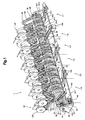
- the device 1 has an elongated processing drum 12 which is rotatably mounted about its horizontal axis 14 and driven by a drive motor 16 in the direction of rotation D.
- the guide means 22 in their radial end regions saddle-shaped pads 24, which extend parallel to the axis 14.
- Each two adjacent guide means 22 define a pocket-shaped receiving part 26, in which in the Fig. 1 invisible feed means 44 (see Fig.
- 3b + c) project in order to advance the printed products 10, which have been placed astride on the supports 24, or printed products 10 'introduced into the receiving parts 26, stepwise along the supports 24 or guide means 22 in the feed direction V.
- the feed means make in the course of one revolution of the processing drum 12 by a Control device 28, for example, a link control, controlled, each a working stroke in the feed direction V and take the printed products 10, 10 'by one step, and a return stroke against the feed direction V, without affecting the printed products 10,10'.
- the processing drum 12 can be divided functionally into directly successive drum sections 34.1, 34.2,..., 34.7 of the same width, this width being slightly smaller than a working stroke of the feed means, but a step by which the printed products 10, 10 'respectively be advanced, corresponds.
- the control device 28 is provided for the feed means.
- the next adjacent drum section 34.2 in the feed direction V is assigned a first feed station 30.
- the Next drum section 34.3 takes place in the embodiment shown except an axial conveying no processing of the second drum section 34.2 supplied printed products 10 instead, in other sections further printed products 10 are placed astride the already laid on the pads 24 printed products 10.
- the drum sections 34 may be associated with other processing stations, as shown in the Fig. 1 by means of a device 36 for the introduction of printed products 10 '(supplements), a schematically indicated device 38 for adhering inserts to the corresponding printed products 10 and also schematically indicated stapler 40 for stitching the collected printed products 10 is shown.
- the device 1 is physically subdivided into individual modules 1.1, 1.2, 1.3,..., 1.6, which are manufactured individually and assembled to the overall device.
- the modules are primarily formed by a subdivision of the drum 12. The boundaries between the modules are indicated here by solid lines.
- a module 1.1, 1.2, 1.3,..., 1.6 in particular has a multiple of the width of a drum section 34, 34.1,..., 34.7.
- the form of the interfaces between the modules 1.1, 1.2, 1.3, ..., 1.6 is below with reference to Fig. 2 . 3a-d described.
- the device 1 has holding devices 42, 43, which surround the processing drum 12 from below approximately in the region of its lower half.
- serving drum holding devices 42 are arranged in particular at the junctions of two modules 1.1, 1.2, 1.3, ..., 1.6.
- Spaced axially therefrom are product holding devices 43 which prevent the printed products 10, 10 'from falling off the pads 24 or from the receiving parts 26 when, together with the pads 24 and receiving members 26, they are the lower half of the orbit about the axis 14 go through.
- Fig. 1 only one drum holding device 42 or product holding device 43 is indicated.
- the functioning of the in the Fig. 1 shown device is as follows.
- the processing drum 12 is rotated in the direction of rotation D, the stored printed products 10 retain their position with respect to the supports 24 until the advancing means 44 each carry out a working stroke. This happens in the Fig. 1 invisible rear upper quadrant of the processing drum 12. This will take the printed products 10 in the drum section 34.3, where no processing takes place.
- the printed products 10 are fed from this drum section 34.3 to the feed section 34.4, where a further printed product 10 is then placed astride on each printed product 10 from the corresponding conveyor 58.
- These two successive printed products 10 are then successively pushed in the course of three further revolutions of the processing drum 12 to the next feeding station 30 associated Zuurerabites, where in turn another printed product 10 is stored astride it.
- the printed products 10 are supplied in this manner stepwise in the course of each revolution to a subsequent drum section 34, where further processing of the printed products 10 may take place or not. If the finished processed printed products 10 reach the feed section 34.7 at the end of the processing drum 12, the finished products are taken over by the gripper conveyor 140 and taken away.
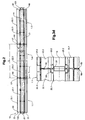
- Fig. 2 shows a processing drum 12 constructed from three individual modules 1.1, 1.2, 1.3.
- Fig. 3a-d show detail views of this Processing drum or its modules;
- Fig. 3a shows a view taken along the axis of rotation 14 partially in section of an end portion of a module 1.1 illustrating the interface;
- Fig. 3b shows a front view of such an interface or on the support member 50;
- Fig. 3c shows a section perpendicular to the axis of rotation 14 away from the support member to illustrate the support means 22 and
- Fig. 3d shows the boundary region of two mutually coupled modules 1.1, 1.2.
- Fig. 2 is the one at the EP-A 0 550 828 one-piece drum shaft 20 according to the invention in at least three sections 20.1, 20.2, 20.3 subdivided; These tubular drum shaft sections correspond to the main body of a module 1.1, 1.2, 1.3.
- the modules may further comprise one or more delivery or removal stations located in Fig. 2 . 3a-d not shown.
- the modules 1.1, 1.2, 1.3 each have the same length L.
- the main bodies 20.1, 20.2, 20.3 of the modules are further subdivided here, in each case into three mutually coupled segments 21, which preferably have a uniform length 1.
- the module length L is equal to three times the length of the tube segments 21 plus the length of a coupling 55 '.
- L corresponds, for example, to the width of four or six sections 34. For producing a module of shorter length (see, for example, module 1.4 in FIG Fig. 4 ), only two segments 21 can be connected to each other.
- the base bodies 20. 1, 20. 2, 20. 3 have support elements 50 that protrude outward radially beyond the main bodies 20. 1, 20. 2, 20. 3 at their axial end regions from the axis of rotation 14.
- the radius r2 of the support member 50 is significantly, preferably by 1.5 to 3 times, greater than the radius r1 of the body.
- the support members 50 take the form of spoked wheels 52, as in FIG Fig. 3b is shown in more detail.
- the support members 50 have a perpendicular to the axis of rotation 14 extending front surface 53 (see Fig. 3a + b), which terminates in the axial direction flush with the base body (not shown here) or surmounting this ( Fig.
- connection points 56 of two support elements 50 are to increase the torsional stiffness preferably outside the radius r1 in the radially outer regions of the support member 50th
- the support elements 50 are connected by means of suitable coupling elements 55 rigidly connected to the end regions of the base body 20.1, 20.2, 20.3. Since the support elements 50 protrude here in the axial direction over the main body 20.1, 20.2, 20.3, there is between each two main bodies 20.1, 20.2, 20.3 in each case a further coupling piece 55 '(FIG. Fig. 3d ), which is rigidly connected to the coupling elements 55 and here has the shape of a pipe section with approximately the same radius as the base body 20.1, 20.2, 20.3 and a flange projecting outwardly in the axial direction. Supporting elements 50 and coupling piece 55 'or base body 20.1, 20.2, 20.3 and coupling piece 55' may also be in one piece.
- the modules 1.1, 1.2, 1.3 have on the main body 20.1, 20.2, 20.3 arranged guide means sections 22.1, 22.2, 22.3, which are coupled to an axially continuous guide means 22 of the device 1. These guide means sections 22.1, 22.2, 22.3 are anchored in their axial end regions on the support elements 50. Thus, a twisting of the guide means is counteracted even with large overall lengths of the drum 12.
- Fig. 2 shows, are at the respective outer, not connected to another module end portions of the overall device such support elements 50th arranged, which serve for anchoring the guide means sections 22.1, 22.2 of the respective module.
- These end regions have a coupling 120, via which the drum shaft 12 is connected to the drive 16 and / or mounted in the frame 18.
- the guide means sections 22.1, 22.2, 22.3 have the shape of a profile sheet with a substantially straight guide surface 22a and a notched back surface 22b.
- the notches or the entire rear surface 22b serve as guides for the feed means 44. These are in Fig. 3b and 3c indicated.
- the feed means 44 execute only a certain stroke, which is smaller than the distance between two support members 50, their movement is not hindered by the support members 50.
- Each of a common receiving part 26 associated feed 44 of two adjacent modules 1.1, 1.2 are coupled together by suitable means, for example, the support members 50, for example, by rods.
- they can as in the undivided device, eg according to EP-A 0 550 828 be driven by a common drive and controlled by a common control device.
- the spoke wheel 52 has seen in the axial direction, a straight front and back surface and a small compared to the length L of the module axial extent. In the circumferential direction, the spoked wheel 52 has the same number of spokes 54 as the drum 12 has support elements 22. The notches between the spokes 54 serve for the unimpeded passage of the printed products 10, 10 '.
- the sections 24.1, 24.2 of the above-described support 24 are formed here from an angled further profile sheet, which on the guide means sections 22.1, 22.2, 22.3 is attached, but may also be integrally formed therewith.
- the guide means sections 22.1, 22.2, 22.3 are at their ends facing the axis of rotation 14 in grooves 80 in the drum shaft 12 and their sections 12.1, 12.2, which extend over the entire length of the drum shaft 12 and the corresponding portion or only in the area of the spoked wheel 52.
- the guide means sections 22.1, 22.2, 22.3 are anchored to the spokes 54 of the spoke wheel 52. These have to the profile of the rear surface 22b of the guide means sections 22.1, 22.2, 22.3 substantially complementary shape, as in Fig. 3b shown.
- Fig. 3c shows a section through a module in a central region, ie away from the support elements 50.
- the structure here corresponds to a non-modular device, eg according to EP-A 0 550 828 , For the sake of clarity, only a few guide means sections 22.1, 22.2, 22.3 and only one advancing means 44 are shown.
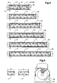
- FIG. 4 shows several variants of a built-up of different modules device. All variants include a first module 1.1 and a second module 1.2. Both modules are basically as related to Fig. 2 . 3a-d constructed and have approximately the same length measured in the axial direction L. In their end regions, the device 1 is mounted on a machine frame 18. Outside the end regions, the device is supported by holding devices, not shown here.
- the first module 1.1 arranged here in each case in the right-hand end region of the device comprises a control device 28 for the advancing means 44.
- This preferably comprises a slide control 108, which is only schematically indicated here, in particular as in FIG EP-A 0 550 828 described.
- the advancing means 44 of all modules 1.1, 1.2 are coupled together and therefore controllable by the same control device 28. In particular, they perform a synchronous lifting movement in the axial direction and a synchronous clamping movement in the circumferential direction.
- the first module 1.1 is also coupled to four feed stations 30, which are indicated here only schematically, but for example in the EP-A 0 550 828 are described in more detail.
- the second module 1.2 arranged here in each case in the left end region of the device comprises a removal station 32, which is also shown only schematically. It has approximately the same width as a feed station 30, of which the second module 1.2 has five. As in Fig. 5 sketched, the Weggarstation 32 is disposed below the drum 12. It includes, for example, a stapler.
- the device composed of these basic elements 1.1, 1.2 can be supplemented by further modules 1.3, 1.4.
- Two different types of intermediate modules are in the right part of the Fig. 4 outlined.
- a first intermediate module 1.3 has six feed stations 30 and an overall length L which corresponds to the length of a basic element 1.1, 1.2.
- a second intermediate module 1.4. has only four feed stations 30 and a correspondingly reduced total length L ', which is about 2/3 of the length L.
- one, two or more of these intermediate modules 1.3, 1.4 can be connected between the basic modules 1.1, 1.2.
- Fig. 4 shows various examples of devices with a total of 9, 13, 15, 17, 19 and 21 feed stations. Thanks to the uniform interfaces of the modules, the modular system allows simple extension of existing devices. According to the invention, it is also possible to produce the required stability.
- Fig. 6 shows an overview of different composed of modules devices, in each case the in Fig. 5 sketched Wegfoodstation 32 is indicated with stitching unit.
- the devices do not differ in principle from those Fig. 4 with two exceptions explained below:
- FIG. 7 shows a partially cutaway view of an inventive device 1 in the direction of the axis of rotation 14.
- the drum 12 with the drum shaft 20 and disposed thereon radially projecting guide means 22 which form in the axial direction continuous guide surfaces or pocket-shaped receiving parts 26.
- the modular construction of the device and the support elements 50 according to the invention are not visible in this illustration.
- Below the drum are holders 42 for the actual drum 12 and holding devices 43, which prevent falling out of the products from the receiving parts 26.
- the drum 12 and these holding devices 42, 43 are located in a machine frame 18. This has a passage for a Wegrawstation 32, which here comprises a gripper conveyor 140.
- the holding devices 42 for the drum 12 comprises a support belt 110, which is guided over a plurality of circulation rollers 112 so that the drum 12 facing the strand about the lower third of the drum is supported. This prevents sagging.
- the support band 110 preferably has an unstructured surface. As a result, problems with the synchronization of the conditions and any adapted thereto, circumferentially moving holding elements are avoided. These can be used, for example, in the EP-A 0 550 828 described holding device occur in the cross-sectionally V-shaped holding elements engage around the supports and thereby supported. Nevertheless, in principle, such a holding device can be used here.
- the holding device 42 for the drum is preferably arranged in the region of the interface between two modules.
- the controller 28 is configured so that the products are located near the seams in the upper half of the orbit 12.
- the support band 110 of the holding device 42 therefore does not come into contact with the products; thus there is no danger that they are damaged between drum 12 and support belt 110.
- Holding devices 43 for the products are arranged laterally of the drum holding device 42 in the areas. It also comprises a support band 114, which rotates over deflection rollers 116 and rests in the lower half of the drum on the supports 24 and the receiving parts 26 closes. In the present case, the support band 114 does not have to exert a large force on the drum 12, because only the weight of the products must be taken to prevent them from falling out.
- the described functional division of the holding devices 42, 43 in holding devices for the drum and holding devices for the products and their spatial separation has the advantage that both the drum and the products safely and easily - namely with a support band - can be supported without the Mechanically impair products.
- This concept can also be used with advantage in non-modular devices.
Landscapes
- Collation Of Sheets And Webs (AREA)
- Electrical Discharge Machining, Electrochemical Machining, And Combined Machining (AREA)
- Drilling And Boring (AREA)
- Feeding Of Articles By Means Other Than Belts Or Rollers (AREA)
- Folding Of Thin Sheet-Like Materials, Special Discharging Devices, And Others (AREA)
- Screen Printers (AREA)
- Discharge By Other Means (AREA)
Applications Claiming Priority (1)
| Application Number | Priority Date | Filing Date | Title |
|---|---|---|---|
| CH7692007 | 2007-05-11 |
Publications (2)
| Publication Number | Publication Date |
|---|---|
| EP1990301A1 EP1990301A1 (de) | 2008-11-12 |
| EP1990301B1 true EP1990301B1 (de) | 2010-06-30 |
Family
ID=38461266
Family Applications (1)
| Application Number | Title | Priority Date | Filing Date |
|---|---|---|---|
| EP08405128A Not-in-force EP1990301B1 (de) | 2007-05-11 | 2008-05-08 | Modulare Bearbeitungsvorrichtung sowie Bausatz zum Aufbau einer solchen Bearbeitungsvorrichtung |
Country Status (6)
| Country | Link |
|---|---|
| US (1) | US7959144B2 (da) |
| EP (1) | EP1990301B1 (da) |
| AT (1) | ATE472502T1 (da) |
| AU (1) | AU2008201901B2 (da) |
| CA (1) | CA2629506C (da) |
| DK (1) | DK1990301T3 (da) |
Families Citing this family (1)
| Publication number | Priority date | Publication date | Assignee | Title |
|---|---|---|---|---|
| CH703176A1 (de) * | 2010-05-21 | 2011-11-30 | Ferag Ag | Druckweiterverarbeitungsanlage und Verfahren zum Betrieb einer Druckweiterverarbeitungsanlage. |
Family Cites Families (7)
| Publication number | Priority date | Publication date | Assignee | Title |
|---|---|---|---|---|
| DE345276C (de) | 1919-11-30 | 1921-12-08 | Johannes Nienhold | Gas- oder Dampfentladungsroehre mit negativer Charakteristik |
| CH584153A5 (da) * | 1973-10-10 | 1977-01-31 | Ferag Ag | |
| CH649267A5 (de) * | 1980-11-17 | 1985-05-15 | Ferag Ag | Verfahren und vorrichtung zum einbringen wenigstens einer einlage in druckprodukte. |
| CH667621A5 (de) * | 1985-06-04 | 1988-10-31 | Grapha Holding Ag | Sammelhefter. |
| ATE85028T1 (de) | 1988-05-11 | 1993-02-15 | Ferag Ag | Einrichtung zum sammeln von gefalzten druckbogen. |
| EP0550828B1 (de) | 1992-01-10 | 1995-08-09 | Ferag AG | Verfahren und Vorrichtung zum Verarbeiten von Druckereiprodukten |
| DE59506062D1 (de) * | 1994-03-08 | 1999-07-08 | Ferag Ag | Vorrichtung zum Herstellen von mehrteiligen Druckerzeugnissen |
-
2008
- 2008-04-21 CA CA2629506A patent/CA2629506C/en not_active Expired - Fee Related
- 2008-04-30 AU AU2008201901A patent/AU2008201901B2/en not_active Ceased
- 2008-05-07 US US12/116,553 patent/US7959144B2/en not_active Expired - Fee Related
- 2008-05-08 EP EP08405128A patent/EP1990301B1/de not_active Not-in-force
- 2008-05-08 DK DK08405128.3T patent/DK1990301T3/da active
- 2008-05-08 AT AT08405128T patent/ATE472502T1/de active
Also Published As
| Publication number | Publication date |
|---|---|
| AU2008201901B2 (en) | 2013-03-28 |
| US7959144B2 (en) | 2011-06-14 |
| US20080277859A1 (en) | 2008-11-13 |
| EP1990301A1 (de) | 2008-11-12 |
| CA2629506A1 (en) | 2008-11-11 |
| DK1990301T3 (da) | 2010-10-25 |
| ATE472502T1 (de) | 2010-07-15 |
| AU2008201901A1 (en) | 2008-11-27 |
| CA2629506C (en) | 2015-10-13 |
Similar Documents
| Publication | Publication Date | Title |
|---|---|---|
| EP0550828B1 (de) | Verfahren und Vorrichtung zum Verarbeiten von Druckereiprodukten | |
| DE2803223C2 (da) | ||
| EP0341425B1 (de) | Einrichtung zum Sammeln von gefalzten Druckbogen | |
| DE3620945C2 (de) | Vorrichtung zum Sammeln von gefalzten Druckbogen | |
| EP0341423B1 (de) | Einrichtung zum Zusammentragen, Einstecken und Sammeln von Druckereiprodukten | |
| DE3645393B4 (de) | Sammelhefter | |
| EP0341424B1 (de) | Einrichtung zum Verarbeiten von Druckereiprodukten | |
| DE3635387A1 (de) | Verfahren und vorrichtung zur neupositionierung von einzelartikeln | |
| DE19523164A1 (de) | Flexibles Fördersystem | |
| EP0675005A1 (de) | Einrichtung zum Klebebinden von Druckereiprodukten | |
| EP1539624B1 (de) | Fördertechnische vorrichtung | |
| EP0680916B1 (de) | Verfahren zum Verarbeiten von Druckereiprodukten | |
| EP0210494B1 (de) | Vorrichtung zum Sammeln von gefalzten Druckbogen | |
| EP0344102B1 (de) | Einstecksystem für Druckprodukte | |
| EP1351873B1 (de) | Vorrichtung zum verarbeiten von druckereiprodukten | |
| EP0681979B1 (de) | Einrichtung zum Verarbeiten von Druckereiprodukten | |
| DE2624812A1 (de) | Einwickelmaschine | |
| EP1990301B1 (de) | Modulare Bearbeitungsvorrichtung sowie Bausatz zum Aufbau einer solchen Bearbeitungsvorrichtung | |
| DE2230060C2 (de) | Vorrichtung zur Förderung vereinzelter Stangen | |
| EP1418146B1 (de) | Vorrichtung zum Sammeln und Bearbeiten von gefalteten Druckprodukten | |
| EP2205514B1 (de) | Einrichtung und verfahren zum herstellen von mehrteiligen druckerzeugnissen | |
| EP1312270A1 (de) | Vorrichtung zum Herstellen von Filterzigaretten | |
| DE19623307A1 (de) | Vorrichtung zum Verarbeiten von Druckereiprodukten | |
| EP0903308B1 (de) | Zellenrad zur Uebergabe von Gegenständen von einem ersten Fördermittel an ein zweites Fördermittel | |
| EP2383214B1 (de) | Zusammentragvorrichtung |
Legal Events
| Date | Code | Title | Description |
|---|---|---|---|
| PUAI | Public reference made under article 153(3) epc to a published international application that has entered the european phase |
Free format text: ORIGINAL CODE: 0009012 |
|
| AK | Designated contracting states |
Kind code of ref document: A1 Designated state(s): AT BE BG CH CY CZ DE DK EE ES FI FR GB GR HR HU IE IS IT LI LT LU LV MC MT NL NO PL PT RO SE SI SK TR |
|
| AX | Request for extension of the european patent |
Extension state: AL BA MK RS |
|
| 17P | Request for examination filed |
Effective date: 20090226 |
|
| 17Q | First examination report despatched |
Effective date: 20090325 |
|
| AKX | Designation fees paid |
Designated state(s): AT BE BG CH CY CZ DE DK EE ES FI FR GB GR HR HU IE IS IT LI LT LU LV MC MT NL NO PL PT RO SE SI SK TR |
|
| GRAP | Despatch of communication of intention to grant a patent |
Free format text: ORIGINAL CODE: EPIDOSNIGR1 |
|
| GRAS | Grant fee paid |
Free format text: ORIGINAL CODE: EPIDOSNIGR3 |
|
| GRAA | (expected) grant |
Free format text: ORIGINAL CODE: 0009210 |
|
| AK | Designated contracting states |
Kind code of ref document: B1 Designated state(s): AT BE BG CH CY CZ DE DK EE ES FI FR GB GR HR HU IE IS IT LI LT LU LV MC MT NL NO PL PT RO SE SI SK TR |
|
| REG | Reference to a national code |
Ref country code: GB Ref legal event code: FG4D Free format text: NOT ENGLISH Ref country code: CH Ref legal event code: EP |
|
| REG | Reference to a national code |
Ref country code: IE Ref legal event code: FG4D Free format text: LANGUAGE OF EP DOCUMENT: GERMAN |
|
| REF | Corresponds to: |
Ref document number: 502008000857 Country of ref document: DE Date of ref document: 20100812 Kind code of ref document: P |
|
| REG | Reference to a national code |
Ref country code: CH Ref legal event code: NV Representative=s name: FREI PATENTANWALTSBUERO AG |
|
| REG | Reference to a national code |
Ref country code: SE Ref legal event code: TRGR |
|
| REG | Reference to a national code |
Ref country code: DK Ref legal event code: T3 |
|
| REG | Reference to a national code |
Ref country code: NL Ref legal event code: VDEP Effective date: 20100630 |
|
| PG25 | Lapsed in a contracting state [announced via postgrant information from national office to epo] |
Ref country code: LT Free format text: LAPSE BECAUSE OF FAILURE TO SUBMIT A TRANSLATION OF THE DESCRIPTION OR TO PAY THE FEE WITHIN THE PRESCRIBED TIME-LIMIT Effective date: 20100630 Ref country code: NO Free format text: LAPSE BECAUSE OF FAILURE TO SUBMIT A TRANSLATION OF THE DESCRIPTION OR TO PAY THE FEE WITHIN THE PRESCRIBED TIME-LIMIT Effective date: 20100930 |
|
| LTIE | Lt: invalidation of european patent or patent extension |
Effective date: 20100630 |
|
| PG25 | Lapsed in a contracting state [announced via postgrant information from national office to epo] |
Ref country code: HR Free format text: LAPSE BECAUSE OF FAILURE TO SUBMIT A TRANSLATION OF THE DESCRIPTION OR TO PAY THE FEE WITHIN THE PRESCRIBED TIME-LIMIT Effective date: 20100630 Ref country code: SI Free format text: LAPSE BECAUSE OF FAILURE TO SUBMIT A TRANSLATION OF THE DESCRIPTION OR TO PAY THE FEE WITHIN THE PRESCRIBED TIME-LIMIT Effective date: 20100630 Ref country code: LV Free format text: LAPSE BECAUSE OF FAILURE TO SUBMIT A TRANSLATION OF THE DESCRIPTION OR TO PAY THE FEE WITHIN THE PRESCRIBED TIME-LIMIT Effective date: 20100630 Ref country code: FI Free format text: LAPSE BECAUSE OF FAILURE TO SUBMIT A TRANSLATION OF THE DESCRIPTION OR TO PAY THE FEE WITHIN THE PRESCRIBED TIME-LIMIT Effective date: 20100630 |
|
| PG25 | Lapsed in a contracting state [announced via postgrant information from national office to epo] |
Ref country code: PL Free format text: LAPSE BECAUSE OF FAILURE TO SUBMIT A TRANSLATION OF THE DESCRIPTION OR TO PAY THE FEE WITHIN THE PRESCRIBED TIME-LIMIT Effective date: 20100630 |
|
| PG25 | Lapsed in a contracting state [announced via postgrant information from national office to epo] |
Ref country code: EE Free format text: LAPSE BECAUSE OF FAILURE TO SUBMIT A TRANSLATION OF THE DESCRIPTION OR TO PAY THE FEE WITHIN THE PRESCRIBED TIME-LIMIT Effective date: 20100630 Ref country code: NL Free format text: LAPSE BECAUSE OF FAILURE TO SUBMIT A TRANSLATION OF THE DESCRIPTION OR TO PAY THE FEE WITHIN THE PRESCRIBED TIME-LIMIT Effective date: 20100630 |
|
| REG | Reference to a national code |
Ref country code: IE Ref legal event code: FD4D |
|
| PG25 | Lapsed in a contracting state [announced via postgrant information from national office to epo] |
Ref country code: IS Free format text: LAPSE BECAUSE OF FAILURE TO SUBMIT A TRANSLATION OF THE DESCRIPTION OR TO PAY THE FEE WITHIN THE PRESCRIBED TIME-LIMIT Effective date: 20101030 Ref country code: CY Free format text: LAPSE BECAUSE OF FAILURE TO SUBMIT A TRANSLATION OF THE DESCRIPTION OR TO PAY THE FEE WITHIN THE PRESCRIBED TIME-LIMIT Effective date: 20100630 Ref country code: CZ Free format text: LAPSE BECAUSE OF FAILURE TO SUBMIT A TRANSLATION OF THE DESCRIPTION OR TO PAY THE FEE WITHIN THE PRESCRIBED TIME-LIMIT Effective date: 20100630 Ref country code: RO Free format text: LAPSE BECAUSE OF FAILURE TO SUBMIT A TRANSLATION OF THE DESCRIPTION OR TO PAY THE FEE WITHIN THE PRESCRIBED TIME-LIMIT Effective date: 20100630 Ref country code: SK Free format text: LAPSE BECAUSE OF FAILURE TO SUBMIT A TRANSLATION OF THE DESCRIPTION OR TO PAY THE FEE WITHIN THE PRESCRIBED TIME-LIMIT Effective date: 20100630 |
|
| PG25 | Lapsed in a contracting state [announced via postgrant information from national office to epo] |
Ref country code: IT Free format text: LAPSE BECAUSE OF FAILURE TO SUBMIT A TRANSLATION OF THE DESCRIPTION OR TO PAY THE FEE WITHIN THE PRESCRIBED TIME-LIMIT Effective date: 20100630 |
|
| PG25 | Lapsed in a contracting state [announced via postgrant information from national office to epo] |
Ref country code: IE Free format text: LAPSE BECAUSE OF FAILURE TO SUBMIT A TRANSLATION OF THE DESCRIPTION OR TO PAY THE FEE WITHIN THE PRESCRIBED TIME-LIMIT Effective date: 20100630 |
|
| PLBE | No opposition filed within time limit |
Free format text: ORIGINAL CODE: 0009261 |
|
| STAA | Information on the status of an ep patent application or granted ep patent |
Free format text: STATUS: NO OPPOSITION FILED WITHIN TIME LIMIT |
|
| PG25 | Lapsed in a contracting state [announced via postgrant information from national office to epo] |
Ref country code: GR Free format text: LAPSE BECAUSE OF FAILURE TO SUBMIT A TRANSLATION OF THE DESCRIPTION OR TO PAY THE FEE WITHIN THE PRESCRIBED TIME-LIMIT Effective date: 20101001 |
|
| 26N | No opposition filed |
Effective date: 20110331 |
|
| PG25 | Lapsed in a contracting state [announced via postgrant information from national office to epo] |
Ref country code: ES Free format text: LAPSE BECAUSE OF FAILURE TO SUBMIT A TRANSLATION OF THE DESCRIPTION OR TO PAY THE FEE WITHIN THE PRESCRIBED TIME-LIMIT Effective date: 20101011 |
|
| REG | Reference to a national code |
Ref country code: DE Ref legal event code: R097 Ref document number: 502008000857 Country of ref document: DE Effective date: 20110330 |
|
| BERE | Be: lapsed |
Owner name: FERAG AG Effective date: 20110531 |
|
| PG25 | Lapsed in a contracting state [announced via postgrant information from national office to epo] |
Ref country code: MC Free format text: LAPSE BECAUSE OF NON-PAYMENT OF DUE FEES Effective date: 20110531 Ref country code: MT Free format text: LAPSE BECAUSE OF FAILURE TO SUBMIT A TRANSLATION OF THE DESCRIPTION OR TO PAY THE FEE WITHIN THE PRESCRIBED TIME-LIMIT Effective date: 20100630 |
|
| REG | Reference to a national code |
Ref country code: FR Ref legal event code: ST Effective date: 20120131 |
|
| PG25 | Lapsed in a contracting state [announced via postgrant information from national office to epo] |
Ref country code: BE Free format text: LAPSE BECAUSE OF NON-PAYMENT OF DUE FEES Effective date: 20110531 |
|
| PG25 | Lapsed in a contracting state [announced via postgrant information from national office to epo] |
Ref country code: FR Free format text: LAPSE BECAUSE OF NON-PAYMENT OF DUE FEES Effective date: 20110531 |
|
| PGFP | Annual fee paid to national office [announced via postgrant information from national office to epo] |
Ref country code: DK Payment date: 20120521 Year of fee payment: 5 |
|
| PGFP | Annual fee paid to national office [announced via postgrant information from national office to epo] |
Ref country code: SE Payment date: 20120522 Year of fee payment: 5 |
|
| GBPC | Gb: european patent ceased through non-payment of renewal fee |
Effective date: 20120508 |
|
| PG25 | Lapsed in a contracting state [announced via postgrant information from national office to epo] |
Ref country code: GB Free format text: LAPSE BECAUSE OF NON-PAYMENT OF DUE FEES Effective date: 20120508 |
|
| PG25 | Lapsed in a contracting state [announced via postgrant information from national office to epo] |
Ref country code: LU Free format text: LAPSE BECAUSE OF NON-PAYMENT OF DUE FEES Effective date: 20110508 |
|
| PG25 | Lapsed in a contracting state [announced via postgrant information from national office to epo] |
Ref country code: PT Free format text: LAPSE BECAUSE OF NON-PAYMENT OF DUE FEES Effective date: 20100630 |
|
| PG25 | Lapsed in a contracting state [announced via postgrant information from national office to epo] |
Ref country code: BG Free format text: LAPSE BECAUSE OF FAILURE TO SUBMIT A TRANSLATION OF THE DESCRIPTION OR TO PAY THE FEE WITHIN THE PRESCRIBED TIME-LIMIT Effective date: 20100930 Ref country code: TR Free format text: LAPSE BECAUSE OF FAILURE TO SUBMIT A TRANSLATION OF THE DESCRIPTION OR TO PAY THE FEE WITHIN THE PRESCRIBED TIME-LIMIT Effective date: 20100630 |
|
| PG25 | Lapsed in a contracting state [announced via postgrant information from national office to epo] |
Ref country code: HU Free format text: LAPSE BECAUSE OF FAILURE TO SUBMIT A TRANSLATION OF THE DESCRIPTION OR TO PAY THE FEE WITHIN THE PRESCRIBED TIME-LIMIT Effective date: 20100630 |
|
| REG | Reference to a national code |
Ref country code: SE Ref legal event code: EUG |
|
| PG25 | Lapsed in a contracting state [announced via postgrant information from national office to epo] |
Ref country code: SE Free format text: LAPSE BECAUSE OF NON-PAYMENT OF DUE FEES Effective date: 20130509 |
|
| REG | Reference to a national code |
Ref country code: DK Ref legal event code: EBP Effective date: 20130531 |
|
| PG25 | Lapsed in a contracting state [announced via postgrant information from national office to epo] |
Ref country code: DK Free format text: LAPSE BECAUSE OF NON-PAYMENT OF DUE FEES Effective date: 20130531 |
|
| REG | Reference to a national code |
Ref country code: AT Ref legal event code: MM01 Ref document number: 472502 Country of ref document: AT Kind code of ref document: T Effective date: 20130508 |
|
| PG25 | Lapsed in a contracting state [announced via postgrant information from national office to epo] |
Ref country code: AT Free format text: LAPSE BECAUSE OF NON-PAYMENT OF DUE FEES Effective date: 20130508 |
|
| PGFP | Annual fee paid to national office [announced via postgrant information from national office to epo] |
Ref country code: DE Payment date: 20180522 Year of fee payment: 11 |
|
| PGFP | Annual fee paid to national office [announced via postgrant information from national office to epo] |
Ref country code: CH Payment date: 20180802 Year of fee payment: 11 |
|
| REG | Reference to a national code |
Ref country code: DE Ref legal event code: R119 Ref document number: 502008000857 Country of ref document: DE |
|
| REG | Reference to a national code |
Ref country code: CH Ref legal event code: PL |
|
| PG25 | Lapsed in a contracting state [announced via postgrant information from national office to epo] |
Ref country code: LI Free format text: LAPSE BECAUSE OF NON-PAYMENT OF DUE FEES Effective date: 20190531 Ref country code: CH Free format text: LAPSE BECAUSE OF NON-PAYMENT OF DUE FEES Effective date: 20190531 |
|
| PG25 | Lapsed in a contracting state [announced via postgrant information from national office to epo] |
Ref country code: DE Free format text: LAPSE BECAUSE OF NON-PAYMENT OF DUE FEES Effective date: 20191203 |