EP1990396A1 - Produit de depart phosphore et procede de production d'un alliage pour produit de depart phosphore - Google Patents
Produit de depart phosphore et procede de production d'un alliage pour produit de depart phosphore Download PDFInfo
- Publication number
- EP1990396A1 EP1990396A1 EP07737422A EP07737422A EP1990396A1 EP 1990396 A1 EP1990396 A1 EP 1990396A1 EP 07737422 A EP07737422 A EP 07737422A EP 07737422 A EP07737422 A EP 07737422A EP 1990396 A1 EP1990396 A1 EP 1990396A1
- Authority
- EP
- European Patent Office
- Prior art keywords
- metal elements
- elements
- raw material
- phosphor
- phosphor raw
- Prior art date
- Legal status (The legal status is an assumption and is not a legal conclusion. Google has not performed a legal analysis and makes no representation as to the accuracy of the status listed.)
- Withdrawn
Links
Images


Classifications
-
- C—CHEMISTRY; METALLURGY
- C09—DYES; PAINTS; POLISHES; NATURAL RESINS; ADHESIVES; COMPOSITIONS NOT OTHERWISE PROVIDED FOR; APPLICATIONS OF MATERIALS NOT OTHERWISE PROVIDED FOR
- C09K—MATERIALS FOR MISCELLANEOUS APPLICATIONS, NOT PROVIDED FOR ELSEWHERE
- C09K11/00—Luminescent materials, e.g. electroluminescent or chemiluminescent
- C09K11/08—Luminescent materials, e.g. electroluminescent or chemiluminescent containing inorganic luminescent materials
- C09K11/64—Luminescent materials, e.g. electroluminescent or chemiluminescent containing inorganic luminescent materials containing aluminium
-
- C—CHEMISTRY; METALLURGY
- C09—DYES; PAINTS; POLISHES; NATURAL RESINS; ADHESIVES; COMPOSITIONS NOT OTHERWISE PROVIDED FOR; APPLICATIONS OF MATERIALS NOT OTHERWISE PROVIDED FOR
- C09K—MATERIALS FOR MISCELLANEOUS APPLICATIONS, NOT PROVIDED FOR ELSEWHERE
- C09K11/00—Luminescent materials, e.g. electroluminescent or chemiluminescent
- C09K11/08—Luminescent materials, e.g. electroluminescent or chemiluminescent containing inorganic luminescent materials
- C09K11/0838—Aluminates; Silicates
-
- C—CHEMISTRY; METALLURGY
- C09—DYES; PAINTS; POLISHES; NATURAL RESINS; ADHESIVES; COMPOSITIONS NOT OTHERWISE PROVIDED FOR; APPLICATIONS OF MATERIALS NOT OTHERWISE PROVIDED FOR
- C09K—MATERIALS FOR MISCELLANEOUS APPLICATIONS, NOT PROVIDED FOR ELSEWHERE
- C09K11/00—Luminescent materials, e.g. electroluminescent or chemiluminescent
- C09K11/08—Luminescent materials, e.g. electroluminescent or chemiluminescent containing inorganic luminescent materials
-
- C—CHEMISTRY; METALLURGY
- C22—METALLURGY; FERROUS OR NON-FERROUS ALLOYS; TREATMENT OF ALLOYS OR NON-FERROUS METALS
- C22C—ALLOYS
- C22C24/00—Alloys based on an alkali or an alkaline earth metal
-
- C—CHEMISTRY; METALLURGY
- C22—METALLURGY; FERROUS OR NON-FERROUS ALLOYS; TREATMENT OF ALLOYS OR NON-FERROUS METALS
- C22C—ALLOYS
- C22C28/00—Alloys based on a metal not provided for in groups C22C5/00 - C22C27/00
Definitions
- the present invention relates to raw materials of phosphors and, in particular, to a phosphor raw material containing constituent elements thereof uniformly.
- a phosphor raw material may include an alloy for phosphor precursor.
- the present invention also relates to a method for producing such an alloy for phosphor precursor.
- Phosphors are used in such apparatuses as fluorescent lights, vacuum fluorescent displays (VFD), field emission displays (FED), plasma display panels (POP), cathode-ray tubes (CRT) and white light-emitting diodes (LED).
- VFD vacuum fluorescent displays
- FED field emission displays
- POP plasma display panels
- CRT cathode-ray tubes
- LED white light-emitting diodes
- a phosphor requires the supply of excitation energy for emitting light. After being excited by a high-energy source that emits vacuum ultraviolet light, ultraviolet light, visible light, electron beams or the like, such a phosphor emits ultraviolet light, visible light or infrared light.
- a high-energy source that emits vacuum ultraviolet light, ultraviolet light, visible light, electron beams or the like
- such a phosphor emits ultraviolet light, visible light or infrared light.
- the long-term exposure of a phosphor to such an energy source may result in the deterioration of brightness.
- nitrides have recently been developed as alternatives to known phosphors, such as silicate, phosphate, aluminate, borate, sulfide and oxysulfide phosphors.
- phosphors such as silicate, phosphate, aluminate, borate, sulfide and oxysulfide phosphors.
- silicon nitride-based multicomponent nitrides and oxynitrides exhibit excellent characteristics as phosphors.
- Such phosphors are synthesized by nitridation alkaline earth metal elements and then mixing the obtained alkaline earth metal element nitrides with silicon nitride or by heating alkali earth metals and silicon imides as raw materials under nitrogen or argon flow. Both synthetic methods require alkaline earth metal element nitrides susceptible to air and moisture as raw materials, and thus are unsuitable for industrial manufacturing.
- Patent Document 2 discloses oxynitride phosphors having the oxynitride structure represented by the general formula M 16 Si 15 O 6 N 32 or the sialon structure represented by one of the general formula MSiAl 2 ON 2 , M 13 Si 18 Al 12 O 18 N 36 , MSi 5 Al 2 ON 9 and M 3 Si 5 AlON 10 . It states that, particularly in the case where M was Sr, heating the mixture of SrCO 3 , AlN and Si 3 N 4 at the ratio of 1:2:1 under a reducing atmosphere (hydrogen-containing nitrogen atmosphere) resulted in the formation of SrSiAl 2 O 3 N 2 :Eu 2+ . This approach provides oxynitride phosphors only and thus does not provide phosphors based on nitrides free from oxygen.
- raw materials of the nitride or oxynitride phosphors described above have low reactivity in a powder form, so in the calcination step the raw materials should be heated with the contact area of each particle thereof being as large as possible in order to promote the solid state reaction between the particles.
- the synthesized phosphor is in the state of being compacted at high temperatures, in other words, in the state of a very hard sintered body.
- Such a sintered body should be ground into fine particles, which is a form suitable for its intended purposes as a phosphor.
- alkaline earth metal element nitrides such as calcium nitride (Ca 3 N 2 ) and strontium nitride (Sr 3 N 2 ) are preferably used.
- Ca 3 N 2 calcium nitride
- strontium nitride Sr 3 N 2
- divalent metal nitrides are likely to react with water to produce hydroxides and thus unstable under a humid atmosphere. This tendency is remarkable especially in the particles of Sr 3 N 2 and metal Sr, so these kinds of nitrides are very difficult to handle.
- Patent Document 3 that describes a method for producing a nitride phosphor using a metal as a starting material was recently published.
- Patent Document 3 an example of the methods for producing an aluminum nitride-based phosphor is disclosed, wherein it is stated that transition elements, rare earth elements, aluminum and alloys thereof can be used as the starting material.
- transition elements, rare earth elements, aluminum and alloys thereof can be used as the starting material.
- no example wherein such an alloy was actually used as the starting material is found and the source of A1 used is metal Al.
- the invention disclosed in this patent document is totally different from the present invention in that it uses a combustion synthesis method wherein starting materials are ignited and instantly heated to a high temperature (3000 K), so the inventors presume that it is difficult to obtain a high-performance phosphor in this method.
- examples of known alloys containing both Si and alkaline earth metal elements are Ca 7 Si, Ca 2 Si, Ca 5 Si 3 , CaSi, Ca 2 Si 2 , Ca 14 Si 19 , Ca 3 Si 4 , SrSi, SrSi 2 , Sr 4 Si 7 Sr 5 Si 3 and Sr 7 Si.
- examples of known alloys containing Si, aluminum and alkaline earth metal elements include Ca(Si 1-x Al x ) 2 , Sr(Si 1-x Al x ) 2 , Ba(Si 1-x Al x ) 2 , Ca 1-x Sr x (Si 1-y Al y ) 2 .
- Non-patent Document 1 PCT Japanese Translation Patent Publication No. 2003-515665
- Patent Document 2 Japanese Unexamined Patent Application Publication No. 2003-206481
- Patent Document 3 Japanese Unexamined Patent Application Publication No. 2005-54182
- Non-patent Document 1 M. Imai, Applied Physics Letters, 80 (2002) 1019-1021
- Non-patent Document 2 M. Imai, Physical Review B, 68, (2003), 064512
- impurities originally contained in raw materials of the phosphor or impurities contaminating the production process would affect the light emission properties of the resulting phosphor even at the slightest amount. This requires the amount of impurities contained in or contaminating raw materials of a phosphor to be as low as possible.
- an alloy produced in known manufacturing processes sometimes contains impurities and thus affects the light emission properties of the resulting phosphor.
- alkaline earth metal elements contained in such a raw material in the form of alloy have low boiling points and are highly volatile, thereby making it difficult to obtain an alloy with an intended composition.
- an object of the present invention is to provide a phosphor raw material that contains little or no impurities and forms a high-performance phosphor.
- a raw material particularly suitable for the production of a phosphor has, in a synchronous distribution chart representing the relationship between the cube root voltage of any one of elements constituting the phosphor raw material and the cube root voltage of another element, the absolute deviation of accidental errors therebetween being equal to or less than a certain value.
- alloy is a particularly preferred form of such a phosphor raw material.
- the inventors also found that an alloy for phosphor precursor wherein the alloy has an intended chemical composition, alkaline earth metal elements and other low-boiling point elements are prevented from volatilizing and the constituent elements of the alloy are uniformly distributed can be obtained at a high reproducibility by melting Si before melting alkaline earth metal elements.
- the prevent invention was made based on the above-mentioned findings.
- the first aspect of the phosphor raw material is an alloy containing at least Si and one or more metal elements other than Si.
- This phosphor raw material may contain one or more activator elements M 1 as the metal elements other than Si.
- This phosphor raw material may contain one or more activator elements M 1 uniformly.
- the second aspect of the phosphor raw material contains tetravalent metal elements M 4 including at least Si and one or more metal elements other than the tetravalent metal elements M 4 , and, in a synchronous distribution chart representing the relationship between the cube root voltage of any one of the metal elements M 4 and the cube root voltage of any one of the metal elements other than the metal elements M 4 , which can be measured using a particle analyzer, the absolute deviation of accidental errors therebetween is equal to or less than 0.19.
- the metal elements other than the metal elements M 4 may be one or more elements selected from the group consisting of activator elements M 1 , divalent metal elements M 2 and trivalent metal elements M 3 .
- This phosphor raw material may contain activator elements M 1 .
- the third aspect of the phosphor raw material contains tetravalent metal elements M 4 including at least Si and one or more activator elements M 1 , and, in a synchronous distribution chart indicating the relationship between the cube root voltage of any one of the metal elements M 4 and the cube root voltage of any one of the activator elements M 1 , which can be measured using a particle analyzer, the absolute deviation of accidental errors therebetween is equal to or less than 0.4.
- the phosphor raw material may be in the form of an alloy.
- the fourth aspect of the phosphor raw material is formed of an alloy containing one or more activator elements M 1 and one or more metal elements other than the activator elements M 1 , and, in a synchronous distribution chart indicating the relationship between the cube root voltage of any one of the activator elements M 1 and the cube root voltage of any one of the metal elements other than the activator elements M 1 , which can be measured using a particle analyzer, the absolute deviation of accidental errors therebetween is equal to or less than 0.4.
- the phosphor raw material in the fourth aspect may contain tetravalent metal elements M 4 including at least Si.
- the phosphor raw material may be an alloy containing activator elements M 1 , divalent metal elements M 2 and tetravalent metal elements M 4 including at least Si.
- This phosphor raw material may be an alloy containing alkaline earth metal elements as the divalent metal elements M 2 or an alloy further containing trivalent metal elements M 3 .
- the activator elements M 1 may be one or more elements selected from the group consisting of Cr, Mn, Fe, Ce, Pr, Nd, Sm, Eu, Tb, Dy, Ho, Er, Tm and Yb.
- the divalent metal elements M 2 may be one or more elements selected from the group consisting of Mg, Ca, Sr, Ba and Zn
- the trivalent metal elements M 3 may be one or more elements selected from the group consisting of Al, Ga, In and Sc
- the tetravalent metal elements M 4 should include at least Si and may further include one or more elements selected from the group consisting of Ge, Sn, Ti, Zr and Hf as needed.
- Ca and/or Sr may account for 50 mol% or more of the divalent metal elements M 2
- Al may account for 50 mol% or more of the trivalent metal elements M 3
- Si may account for 50 mol% or more of the tetravalent metal elements M 4 including at least Si.
- the phosphor raw material may contain Eu as one of the activator elements M 1 , Ca and/or Sr as the divalent metal elements M 2 , Al as one of the trivalent metal elements M 3 , and Si as one of the tetravalent metal elements M 4 including at least Si.
- the fifth aspect relates to a method for producing an alloy for phosphor precursor, wherein the raw material contains tetravalent metal elements M 4 including at least Si and one or more alkaline earth metal elements as divalent metal elements M 2 , and Si and/or an alloy containing Si are first melted and then the alkaline earth metal elements are melted.
- Si and/or the alloy containing Si and the alkaline earth metal elements may be melted by a high-frequency dielectric heating method.
- This method provides a phosphor raw material that contains little or no impurities and forms a high-performance phosphor.
- the use of the phosphor raw material according to the present invention enables producing a phosphor excellent in brightness and other light emission properties at low cost. Also, the present invention enables industrial manufacturing of an alloy for phosphor precursor that contains Si and alkaline earth metal elements.
- the phosphor raw material of the present invention is not particularly limited as long as it can be used as a raw material of a phosphor. It contains two or more of the constituent elements of an intended phosphor and is characterized in that the constituent elements are uniformly distributed.
- the form of the phosphor raw material according to the present invention include a coprecipitating material and an alloy.
- an alloy is preferable because it achieves the uniform distribution of its constituent elements and a high purity.
- a coprecipitating material and an alloy may be used in combination.
- the phosphor raw material of the present invention in the form of alloy may be referred to as "an alloy for phosphor precursor.”
- the alloy describe above should contain two or more of the constituent elements of an intended phosphor.
- the coprecipitating material described above is obtained by the coprecipitation of compounds used as raw materials of a phosphor (Examples thereof include oxides, hydroxides, sulfides, halides, carbonates and sulfates. Such compounds may be referred to as "raw material compounds" hereinafter.), and in such a material, the phosphor constituent elements are mixed partly or completely at the atomic level.
- the coprecipitation is typically carried out by combining raw material compounds each containing a distinct phosphor constituent element with each other, and the obtained coprecipitating material contains two or more phosphor constituent elements.
- each of the constituent elements of the phosphor raw material according to the present invention is not particularly limited as long as it contains two or more of the constituent elements of an intended phosphor. However, it preferably contains activator elements M 1 . Besides the activator elements M 1 , divalent metal elements M 2 , tetravalent metal elements M 4 including at least Si and trivalent metal elements M 3 may be contained therein.
- activator elements M 1 , the divalent metal element M 2 , the trivalent metal elements M 3 and the tetravalent metal elements M 4 including at least Si are the same as those described in the section of [Alloy for phosphor precursor] later.
- the phosphor raw material of the present invention is also characterized in that the constituent elements are uniformly distributed therein.
- the phosphor raw material of the present invention can provide a phosphor that contains little or no impurities and is constituted of uniformly distributed elements, thereby making it possible to produce a phosphor excellent in light emission intensity and other light emission properties.
- the activator elements M 1 which have been difficult to distribute uniformly in a phosphor and/or a phosphor raw material because of their high molecular weights and low content ratios in the raw material, are uniformly distributed in the phosphor raw material according to the present invention.
- the activator elements M 1 act as the luminescent center ions in a phosphor and contribute to light emission by the phosphor, so that the use of a phosphor raw material in which activator elements M 1 are uniformly distributed is very important in improving the light emission properties of the resulting phosphor.
- the uniformity of distribution of constituent elements in a phosphor raw material can be determined with, for example, a particle analyzer (DP-1000 manufactured by HORIBA, Ltd.).
- a particle analyzer DP-1000 manufactured by HORIBA, Ltd.
- the analysis of the phosphor raw material and the alloy for phosphor precursor according to the present invention using a particle analyzer preferably provides the following results.
- the phosphor raw material contains tetravalent metal elements M 4 and one or more activator elements M 1 ; in a synchronous distribution chart representing the relationship between the cube root voltage of any one of the metal elements M 4 and the cube root voltage of any one of the activator elements M 1 , which can be measured using a particle analyzer, the absolute deviation of accidental errors therebetween is typically 0.4 or less, preferably 0.3 or less, more preferably 0.2 or less, and even more preferably 0.15 or less.
- the elements contained in the phosphor raw material in addition to the metal elements M 4 and the activator elements M 1 are preferably one or more elements selected from the group consisting of divalent metal elements M 2 and trivalent metal elements M 3 , and more preferably divalent metal elements M 2 .
- the phosphor raw material is an alloy containing one or more activator elements M 1 and one or more metal elements other than the activator elements M 1 ; in a synchronous distribution chart representing the relationship between the cube root voltage of any one of the activator elements M 1 and the cube root voltage of any one of the metal elements other than the activator elements M 1 , which can be measured using a particle analyzer, the absolute deviation of accidental errors therebetween is typically 0.4 or less, preferably 0.3 or less, more preferably 0.2 or less, and even more preferably 0.15 or less.
- the elements contained in the phosphor raw material in addition to the activator elements M 1 are preferably one or more elements selected from the group consisting of divalent metal elements M 2 , trivalent metal elements M 3 and metal elements M 4 , more preferably one or more elements selected from the group consisting of divalent metal elements M 2 and metal elements M 4 , and even more preferably metal elements M 4 .
- the absolute deviation of accidental errors is typically not less than 0.01.
- sample particles are ionized and excited in a plasma field, and then the intensity of light emitted as the result of the excitation is measured.
- sample particles are first collected on a filter and then aspirated so as to be carried by helium (He) flow to a He plasma field.
- He helium
- the sample particles introduced into the He plasma field are excited and emit rays of light with wavelengths specific to the elements contained therein.
- the light emission intensities for the elements are each measured by a detector as the detection voltages of a photomultiplier.
- each of the measured light emission intensities is supposed to relate to the mass of the relevant element atoms contained in each particle.
- a particle analyzer calculates the cube root of the light emission intensity assuming that sample particles are spheres, and then outputs values relating to the diameter of the sample particles (hereinafter, sometimes referred to as "cube root voltage (value)"). These values give information about the sample particles. Whether the analyzed two or more elements are contained in a single particle or not can be determined based on whether the elements emit rays of light simultaneously or not.
- alloy A an alloy for phosphor precursor (hereinafter, sometimes referred to as "alloy A”) containing Sr, Ca, Al, Si and Eu as an example.
- the light emission intensities of Sr, Ca, Al, Si and Eu atoms are each measured as the detection voltage of a photomultiplier.
- the cube root voltage described above is obtained as the cube root of the measured detection voltage (light emission intensity), and correlates with the diameter of sample particles.
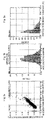
- Fig. 1(a) is a synchronous distribution chart representing the relationship between the cube root voltage of Si atoms (horizontal axis) and the cube root voltage of Eu atoms (vertical axis).
- a single data point (O) corresponds to a single particle of the alloy.
- the synchronous distribution chart of Fig. 1(a) includes the data of particles having the cube root voltage in the range of 0 V to 10 V with respect to the horizontal axis (x-axis) and the vertical axis (y-axis). More specifically, the data points distributed on the horizontal axis (x-axis) correspond to the data of free Si particles or particles with the cube root voltage of Eu equal to or less than the lower detection limit thereof.
- the data points distributed on the vertical axis correspond to the data of free Eu particles or particles with the cube root voltage of Si equal to or less than the lower detection limit thereof.
- the data points having components on both horizontal and vertical axes represent the data of particles of an alloy for phosphor precursor from which Si and Eu atoms simultaneously emit light (hereinafter, sometimes referred to as "synchronized").
- the background is measured and a noise cutoff level is specified so as to eliminate the influence of noise generated by the measuring apparatus.
- the gradient of the group formed by the synchronized particles is calculated by applying the least-square method to each of the chosen data points, and a line approximating the group and passing through the origin of the synchronous distribution chart is made.
- the gradient of the approximate line can also be calculated, and this gradient relates to the mass concentration ratio between the two synchronized elements (e.g., Si/Eu in the case where Si and Eu atoms are synchronized).
- the absolute deviation of accidental errors can be calculated using the following formula B]. It should be noted that the calculation of the accidental errors exclude data points distributed on each axis.
- the absolute deviation of accidental errors is displayed in a histogram of accidental errors ( Fig. 1(b) ).
- the absolute deviation of accidental errors is a numeric form of the variance (dispersion) of synchronized data points, and the larger the absolute deviation of accidental errors is, the greater the variance (dispersion) in the ratio of one element to the other element among the synchronized particles (e.g., the element ratio of Eu to Si; the element ratio herein relates to the mass concentration ratio between the relevant elements) is.
- the absolute deviation of accidental errors close to zero means that the ratio between the relevant elements is completely uniform among the synchronized particles (e.g., in particles with synchronized Si and Eu, the element ratio between Si and Eu is uniform among the particles). Therefore, the smaller the absolute deviation of accidental errors is, the better for the phosphor raw material according to the present invention.
- the alloy for phosphor precursor according to the present invention contains the following elements or other similar elements uniformly.
- the alloy for phosphor precursor according to the present invention may contain activator elements M 1 , divalent metal elements M 2 and tetravalent metal elements M 4 including at least Si.
- Alkaline earth metal elements are preferable as the divalent metal elements M 2 .
- Trivalent metal elements M 3 may be contained as well.
- the activator elements M 1 are preferably one or more elements selected from the group consisting of Cr, Mn, Fe, Ce, Pr, Nd, Sm, Eu, Tb, Dy, Ho, Er, Tm and Yb.
- the alloy for phosphor precursor according to the present invention contains one or more elements selected from the group consisting of Mg, Ca, Sr, Ba and Zn as the divalent metal elements M 2 , one or more elements selected from the group consisting of Al, Ga, In and Sc as the trivalent metal elements M 3 , and one or more elements selected from the group consisting of Si, Ge, Sn, Ti, Zr and Hf as the tetravalent metal elements M 4 .
- Ca and/or Sr account for 50 mol% or more of the divalent metal elements M 2
- Al accounts for 50 mol% or more of the trivalent metal elements M 3
- Si accounts for 50 mold% or more of the tetravalent metal elements M 4 .
- the alloy for phosphor precursor according to the present invention contains Eu as one of the activator elements M 1 , Ca and/or Sr as the divalent metal elements M 2 , Al as one of the trivalent metal elements M 3 , and Si as one of the tetravalent metal elements M 4 .
- alkaline earth metal elements are preferable as metal elements other than the tetravalent metal elements M 4 including at least Si. This makes it possible to produce an industrially useful phosphor that is based on (Sr, Ca) 2 Si 5 N 8 , CaSiAlN 3 or similar compositions containing Si and alkaline earth metal elements and emits red or yellow light.
- the alloy for phosphor precursor according to the present invention preferably contains activator elements M 1 , divalent metal elements M 2 , trivalent metal elements M 3 and tetravalent metal elements M 4 including at least Si, and is expressed by the general formula [1] below.
- activator elements M 1 divalent metal elements M 2 , trivalent metal elements M 3 and tetravalent metal elements M 4 including at least Si
- Such an alloy for phosphor precursor is suitable for the production of composite nitride phosphors expressed by the general formula [2] below.
- the activator elements M 1 may be any kinds of light-emitting ions as long as they can be contained in the host crystal forming such a composite nitride phosphor.
- the use of one or more elements selected from the group consisting of Cr, Mn, Fe, Ce, Pr, Nd, Sm, Eu, Tb, Dy, Ho, Er, Tm and Yb enables the production of a phosphor with excellent light emission properties, and thus is preferable.
- using at least Eu as the activator elements M 1 will result in a phosphor brightness red light, and thus is more preferable.
- one or more coactivator elements may be used as the activator elements M 1 in order to provide the phosphor with high brightness and various functions such as a light-accumulating function.
- the activator elements M 1 In addition to the activator elements M 1 , several divalent, trivalent and tetravalent metal elements may be used.
- the divalent metal elements M 2 are one or more elements selected from the group consisting of Mg, Ca, Sr, Ba and Zn
- the trivalent metal elements M 3 are one or more elements selected from the group consisting of Al, Ga, In and Sc
- the tetravalent metal elements M 4 are one or more elements selected from the group consisting of Si, Ge, Sn, Ti, Zr and Hf.
- composition in which Ca and/or Sr account for 50 mol% or more of the divalent metal elements M 2 would yield a phosphor with excellent light emission properties, and thus is preferable. More preferably Ca and/or Sr account for 80 mol% or more of the divalent metal elements M 2 , even more preferably account for 90 mol% or more thereof, and the most preferably account for 100 mol% thereof.
- composition in which Al accounts for 50 mol% or more of the trivalent metal elements M 3 would yield a phosphor with excellent light emission properties, and thus is preferable. More preferably Al accounts for 80 mol% or more of the trivalent metal elements M 3 , even more preferably accounts for 90 mol% or more thereof, and the most preferably accounts for 100 mol% thereof.
- composition in which Si accounts for 50 mol% or more of the tetravalent metal elements M 4 would yield a phosphor with excellent light emission properties, and thus is preferable. More preferably Si accounts for 80 mol% or more of the trivalent metal elements M 4 including at least Si, even more preferably accounts for 90 mol% or more thereof, and the most preferably accounts for 100 mol% thereof.
- composition in which Ca and/or Sr account for 50 mol% or more of the divalent metal elements M 2 , Al accounts for 50 mol% or more of the trivalent metal elements M 3 , and Si accounts for 50 mol% or more of the tetravalent metal elements M 4 including at least Si would yield a phosphor with markedly excellent light emission properties, and thus is particularly preferable.
- the value a of less than 0.00001 may result in insufficient light emission intensity. However, the value a exceeding 0.15 often results in the drop of the light emission intensity due to promoted concentration quenching. Therefore, raw materials are usually formulated so that the value a is in the range of 0.00001 to 0.15. For the same reason, the value a is preferably in the range of 0.0001 to 0.1, more preferably in the range of 0.001 to 0.05, even more preferably in the range of 0.005 to 0.04, and the most preferably in the range of 0.008 to 0.02.
- the composition of raw materials is controlled so that the sum of the values a and b is 1.
- the value c of less than 0.5 often results in the drop of the production yield of the phosphor. However, in many cases, the value c exceeding 1.5 also reduces the production yield. Therefore, the composition of raw materials is usually chosen so that the value c is in the range of 0.5 to 1.5. Also to provide sufficient light emission intensity, the value c is preferably in the range of 0.5 to 1.5. It is more preferably in the range of 0.6 to 1.4, and the most preferably in the range of 0.8 to 1.2.
- the value d of less than 0.5 often results in the drop of the production yield of the phosphor. However, in many cases, the value d exceeding 1.5 also reduces the production yield. Therefore, the composition of raw materials is usually chosen so that the value d is in the range of 0.5 to 1.5. Also to provide sufficient light emission intensity, the value d is preferably in the range of 0.5 to 1.5. It is more preferably in the range of 0.6 to 1.4, and the most preferably in the range of 0.8 to 1.2.
- the value e is a coefficient that indicates the content ratio of nitrogen.
- Substitution of the requirements 0.5 ⁇ c ⁇ 1.5 and 0.5 ⁇ d ⁇ 1.5 into this formula yields: 1.84 ⁇ e ⁇ 4.17.
- the value e being out of the range of 2.5 to 3.5 often results in the drop of the production yield of the phosphor.
- Possible sources of oxygen contaminating phosphors expressed by the general formula [2] described above include oxygen originally contained as impurities in metal raw material metals, oxygen entering manufacturing processes such as milling and nitridation process, or the like.
- the value f indicating the content ratio of oxygen is preferably in the range of 0 to 0.5 as long as decreases in light emission properties of the resulting phosphor are at acceptable levels.
- the alloy for phosphor precursor according to the present invention contains one or more elements selected from the group consisting of Fe, Ni and Co
- the content ratio of each element is typically 500 ppm or lower, and preferably 100 ppm or lower.
- compositions of such an alloy may include EuSrCaAlSi alloy, EuSrAlSi alloy, EuCaAlSi alloy, EuSrMgAlSi alloy, EuCaMgAlSi alloy, EuCaSi alloy, EuSrCaSi alloy, EuSrSi alloy and EuSrGa alloy.
- More specific examples thereof may include Eu 0.008 Sr 0.792 Ca 0.2 AlSi, Eu 0.008 Sr 0.892 Ca 0.1 AlSi, Eu 0.008 Sr 0.692 Ca 0.3 AlSi, Eu 0.008 Ca 0.892 Mg 0.1 AlSi, Eu 0.006 Sr 0.494 Ca 0.5 AlSi, Eu 0.04 Sr 1.96 Si 5 and Eu 0.01 Sr 1.99 Ga.
- the alloy for phosphor precursor according to the present invention can be used not only as raw materials of the composite oxynitride phosphors described above, but also as raw materials of composite nitride phosphors, composite oxide phosphors, composite sulfide phosphors or the like.
- the alloy for phosphor precursor according to the present invention can be handled in the air even in a powder form, and thus is much easier to handle than known phosphor raw materials containing metal nitrides. Therefore, the shape of the alloy for phosphor precursor according to the present invention is not limited, and examples thereof may include plates, particles, beads, ribbons and blocks.
- the method for producing such an alloy for phosphor precursor according to the present invention is not particularly limited.
- the alloy for phosphor precursor according to the present invention is preferably produced by the method for producing an alloy for phosphor precursor according to the present invention.
- the method for producing an alloy for phosphor precursor according to the present invention is particularly suitable for the production of an alloy for phosphor precursor containing tetravalent metal elements M 4 including at least Si and one or more alkaline earth metal elements as tetravalent metal elements M 2 .
- An example of the method is one in which raw material metals or an alloy thereof are weighed so as to have the composition expressed by the general formula [1] described above and then melted to be alloyed, wherein Si and/or an alloy containing Si with higher melting points (higher boiling points) are first melted and then alkaline earth metals with lower melting points (lower boiling points) are melted.
- metals to be used as activator elements M 1 for the production of the alloy are preferably purified so as to contain impurities at 0.1 mol% or less, and more preferably at 0.01 mol% or less.
- a preferred raw material of Eu is metal Eu.
- the raw materials of elements other than the activator elements M 1 divalent, trivalent and tetravalent metals are used.
- the content ratios of impurities in these metals are preferably 0.1 mol% each or less, and more preferably 0.01 mol% each or less.
- the content ratios thereof are typically 500 ppm each or less, and preferably 100 ppm each or less.
- raw material metals are typically particles or blocks having diameters in the range of few millimeters to several tens of millimeters.
- the raw materials thereof may be particles or blocks, or have other shapes. However, it is preferable to choose an appropriate shape considering the chemical characteristics of the raw materials. For example, Ca may be used in both forms of particles and blocks because of its proven stability in the air, whereas Sr is preferably used in the form of blocks since it has higher chemical activity than Ca.
- the method for melting raw material metals is not particularly limited, and the examples thereof may include the following way of weighing and melting raw material metals.
- metal Si and/or an alloy containing Si with higher melting points are first melted and then alkaline earth metals with lower melting points (lower boiling points) are melted because of the following problem.
- the melting point of Si is 1410°C and close to the boiling points of alkaline earth metals (e.g., Ca, Sr and Ba have boiling points of 1494°C, 1350°C and 1537°C, respectively).
- the boiling point of Sr is lower than the melting point of Si, and this makes it extremely difficult to melt Sr and Si simultaneously.
- this sequence including the first step of melting metal Si and the second step of melting alkaline earth metals yields alloys with a high purity and accordingly the resulting phosphor, which contains such alloys as raw materials, with markedly improved characteristics.
- the method for melting raw material metals in the present invention is not particularly limited, typical examples of such a method include resistance heating, electron beam melting, arc melting and high-frequency dielectric heating (hereinafter, sometimes referred to as "high-frequency dielectric melting").
- high-frequency dielectric melting is preferable, and high-frequency dielectric melting is particularly preferable considering the manufacturing cost.
- the metal Si may be cooled between the steps i) and ii) or directly forwarded to the step of melting alkaline earth metals without being cooled. If the steps i) and ii) are serially performed, a crucible fabricated by coating an electrically conductive vessel with calcia, alumina or other materials that support melting of alkaline earth metals may be used.
- Examples of specific methods in which metal Si or a mother alloy containing Si is first melted and then alkaline earth metals are melted may include the method in which metal Si or a mother alloy containing Si is first melted and then alkaline earth metals are added thereto.
- Si may be alloyed with a metal M other than divalent metal elements M 2 so as to have electrical conductivity.
- the melting point of the resulting alloy is preferably lower than that of Si.
- the alloy of Si and Al is particularly preferable because the melting point thereof is approximately 1010°C and thus is lower than the boiling points of alkaline earth metal elements.
- the composition thereof is not particularly limited, but the mother alloy preferably electric conductivity.
- the mixing ratio (mole ratio) of the metal M is typically in the range of 0.01 to 5 with the number of moles of Si being 1 so that the resulting mother alloy has a melting point lower than the boiling points of alkaline earth metal elements.
- metal Si may be further added to the mother alloy containing Si.
- metal Si should be melted before alkaline earth metals are melted, but the timing to melt raw material metals other than the metal Si and alkaline earth metals is not particularly limited. Usually, raw material metals with larger amounts or higher melting points are melted in priority to those with smaller amounts or lower melting points.
- an alloy for phosphor precursor that is expressed by the general formula [1] described above and contains Si as one of the tetravalent metal elements M 4 including at least Si and at least Sr as the divalent metal elements M 2 , the following melting steps are preferably used.
- the atmosphere under which such raw material metals are melted is preferably an inert gas, in particular, Ar.
- the pressure used herein is in the range of 1 ⁇ 10 3 Pa to 1 ⁇ 10 6 Pa, and considering the safety, it is advisable that such raw material metals are melted under a pressure equal to or lower than the atmospheric pressure.
- the melted alloy obtained by melting raw material metals may be directly used to produce a nitrogen-containing alloy, it is preferably cast into a mold to form an aggregate (an alloy ingot). In this casting step, however, segregation may occur depending on the rate of cooling the melted alloy, thereby resulting in the uneven distribution of the composition thereof, which is uniform with the alloy being in the melted state. Therefore, the higher the cooling rate is, the better.
- the mold is made of a highly thermally conductive material, such as copper, and has a shape that promotes the diffusion of heat therefrom. Furthermore, the mold is preferably cooled by techniques like water cooling, as needed.
- the melted alloy cast into the mold is set as fast as possible with the help of cooling techniques, such as the use of a mold having a large area of the bottom relative to its thickness.
- the degree of segregation varies depending on the composition of the alloy. It is thus preferable to analyze the samples obtained from several points of the aggregate for their compositions by ICP atomic emission spectrometry or other necessary analytical methods in order to specify the cooling rate required for the prevention of the segregation.
- the atmosphere used in such a casting step is preferably an inert gas, in particular, Ar.
- the alloy ingot obtained in the casting step is then ground to produce alloy powder having desired particle diameters and particle size distribution.
- methods for milling such an ingot may include dry milling and wet milling, wherein an organic solvent such as ethylene glycol, hexane and acetone is used. This milling step is described in detail below taking dry milling as an example.
- This milling step may be divided into several substeps including coase milling, medium milling and fine milling steps.
- the apparatus used may be the same or different among such substeps.
- the coarse milling step herein means the step of milling alloy powder so that approximately 90 wt% of the particles has a diameter of not more than 1 cm, and examples of mills used in this step may include a jaw crusher, a gyratory crusher, a crushing roll and an impact crusher.
- the medium milling step means the step of milling alloy powder so that approximately 90 wt% of the particles has a diameter of not more than 1 mm, and examples of mills used in this step may include a cone crusher, a crushing roll, a hammer mill and a disk mill.
- the fine milling step means the step of milling alloy powder so that the particles have the weight-average median diameter described later, and examples of mills used in this step may include a ball mill, a tube mill, a rod mill, a roller mill, a stamp mill, an edge-runner, a vibrating mill and a jet mill.
- a jet mill is preferably used with the intention of preventing the incorporation of impurities.
- the alloy ingot is preferably ground in advance into particles with diameters of not more than 2 mm for the use of a jet mill.
- Such a jet mill injects a fluid from its nozzle into the atmospheric pressure so as to grind particles with the expansion energy generated in association with the injection, thereby enabling the control of the particle diameter by changing the milling pressure and the prevention of impurity incorporation.
- the gauge pressure for milling is typically in the range of 0.01 MPa to 2 MPa, preferably at least 0.05 MPa and less than 0.4 MPa, and more preferably in the range of 0.1 MPa to 0.3 MPa.
- surfaces to be in contact with particles are preferably lined with ceramic, in particular, alumina, silicon nitride, tungsten carbide, zirconia or the like.
- the milling steps are performed preferably under an inert gas atmosphere, and the oxygen concentration in such an inert gas is preferably 10% or lower, and particularly preferably 5% or lower. Additionally, the lower limit of the oxygen concentration is typically approximately 10 ppm. The oxygen concentration controlled to fall within such a specific range probably contributes to the formation of oxide layers on the alloy powder during the milling step and thereby stabilizes the particles. Milling alloy powder under an atmosphere containing oxygen at a concentration exceeding 5% would involve the risk of dust explosion and thus require equipment for suppressing the generation of dust.
- the kind of the inert gas is not particularly limited, nitrogen, argon, helium or the like is used alone or in combination of two or more thereof. Considering the cost, nitrogen is particularly preferable.
- the alloy powder may be cooled during the milling steps to prevent overheating thereof, as needed.
- the alloy powder ground in the milling step(s) are screened with a screening apparatus based on a mesh such as a vibrating screen and a sifter, an inertial classification apparatus such as an air separator, or a centrifuge such as a cyclone separator so as to have a desired value of the weight-average median diameter D 50 and desired particle size distribution described later.
- a screening apparatus based on a mesh such as a vibrating screen and a sifter
- an inertial classification apparatus such as an air separator
- a centrifuge such as a cyclone separator
- This classification step is also performed preferably under an inert gas atmosphere, and the oxygen concentration in such an inert gas is preferably 10% or lower, and particularly preferably 5% or lower.
- the kind of the inert gas is not particularly limited, nitrogen, argon, helium or the like is used alone or in combination of two or more thereof. Considering the cost, nitrogen is particularly preferable.
- the diameters of the alloy powder should be controlled depending on the activities of metal elements constituting the alloy powder before the primary nitridation process described later.
- the weight-average median diameter D 50 of the alloy powder is typically 100 ⁇ m or less, preferably 80 ⁇ m or less, and particularly preferably 60 ⁇ m or less, as well as is typically 0.1 ⁇ m or more, preferably 0.5 ⁇ m or more, and particularly preferably 1 ⁇ m or more.
- alloy powder containing Sr are highly reactive with a surrounding gas. Therefore, in the case where alloy powder containing Sr are used, it is usually desirable that the weight-average median diameter D 50 thereof is 5 ⁇ m or more.
- This weight-average median diameter D 50 for Sr-containing particles is preferably 8 ⁇ m or more, more preferably 10 ⁇ m or more, and particularly preferably 13 ⁇ m or more.
- a weight-average median diameter D 50 of less than the lower limit described above may lead to the rise of heating rates in nitridation and other reactions and thereby make it difficult to control such reactions.
- a weight-average median diameter D 50 exceeding the upper limit described above may hinder reactions that occur in the inside of the alloy powder, such as nitridation.
- the method for producing a phosphor using the phosphor raw material according to the present invention is not particularly limited as long as it is suitable for the composition and kind of the phosphor raw material or for the production of the intended phosphor.
- the method for producing a phosphor using the alloy for phosphor precursor according to the present invention or an alloy for phosphor precursor formed by the method for producing an alloy for phosphor precursor according to the present invention is not particularly limited, and the reaction conditions used therein are determined based on the kind of a phosphor, such as an oxide phosphor, a sulfide phosphor and a nitride phosphor.
- a phosphor such as an oxide phosphor, a sulfide phosphor and a nitride phosphor.
- the method is described taking nitridation reaction as an example.
- Nitridation of an alloy is performed, for example, in the following manner.
- the object of nitridation i.e., an alloy ingot or alloy powder
- the object of nitridation is first bedded in a crucible or a tray.
- the material of a crucible or a tray used in this step may include boron nitride, silicon nitride, aluminum nitride, tungsten and molybdenum, and boron nitride is preferable because of its excellent corrosion resistance.
- the crucible or tray containing the alloy is placed in a heating furnace having the function of controlling the inside atmosphere, and then the air in this system is fully substituted with a nitrogen-containing gas by allowing the nitrogen-containing gas to flow in the system. If necessary, the system may be evacuated before the introduction of the nitrogen-containing gas.
- Examples of a nitrogen-containing gas used in the nitridation process may include nitrogen, ammonia and a mixed gas of nitrogen and hydrogen.
- the oxygen concentration in the system has an effect on the oxygen content ratio in the resulting phosphor, and a phosphor containing too much oxygen would be insufficient in light emission intensity. Therefore, the lower the oxygen concentration in an atmosphere used in the nitridation process is, the better, and the oxygen concentration is typically 1000 ppm or lower, preferably 100 ppm or lower, and more preferably 10 ppm or lower.
- an oxygen absorbent such as carbon or molybdenum may be placed at the area of the system to be heated in order to reduce the oxygen concentration.
- the pressure of the nitrogen-containing gas which fills the system or flows therein and heated to promote nitridation reaction, may be slightly lower than, equal to or higher than the atmospheric pressure. To prevent the oxygen contained in the air from contaminating the system, however, the pressure is preferably equal to or higher than the atmospheric pressure. If a heating furnace used is less airtight, a pressure of less than the atmospheric pressure would allow a large amount of oxygen to get into the system and result in deterioration of the characteristics of the resulting phosphor.
- the gauge pressure of the nitrogen-containing gas is preferably 0.2 MPa or higher, and the most preferably in the range of 10 MPa to 180 MPa.
- the temperature for heating the alloy is typically 800°C or higher, preferably 1000°C or higher and more preferably 1200°C or higher, as well as is typically 2200°C or lower, preferably 2100°C or lower and more 2000°C or lower.
- the heating temperature of lower than 800°C significantly prolongs the nitridation process and thus is not preferable.
- the heating temperature exceeding 2200°C leads to the volatilization or decomposition of the nitrides formed in the reaction, thereby changing the chemical composition of the resulting nitride phosphor. As a result, the phosphor will have deteriorated characteristics and the reproducibility of the production process will be low.
- the heating time used in the nitridation process is that required for the reaction between the alloy and nitrogen, and is typically one minute or longer, preferably 10 minutes or longer, more preferably 30 minutes or longer and even more preferably 60 minutes or longer. If the heating time is shorter than one minute, the nitridation reaction cannot be completed and thus the resulting phosphor will have deteriorated characteristics.
- the upper limit of the heating time is typically 24 hours considering the production efficiency.
- the method described below may be used as a method for producing a phosphor using the phosphor raw material according to the present invention. This method is particularly useful in producing a phosphor using a coprecipitating material.
- a compound containing one of elements that constitute the intended phosphor such as a nitride, an oxide, a hydroxide, a carbonate, a nitrate, a sulfate, an oxalate, a carboxylate, a halide and a sulfide, may be used as appropriate to achieve the composition of the intended phosphor, in addition to the phosphor raw material according to the present invention.
- the phosphor raw materials are each weighed and then mixed with each other (a mixing step), and the obtained mixture is calcined under predetermined calcination conditions (a calcination step).
- the calcined mixture is ground, washed and surface-treated as needed to form a phosphor.
- an inert gas such as argon gas or nitrogen gas during the weighing, mixing and other steps.
- the method for mixing phosphor raw materials is not particularly limited. Examples of mixing methods may include (A) dry mixing and (B) wet mixing methods described below.
- the mixture obtained in the mixing step described above is usually bedded in a heat-resistant vessel, such as a crucible or a tray, made of a material with low reactivity with the phosphor raw materials, and then calcined.
- a heat-resistant vessel such as a crucible or a tray
- the material of a heat-resistant vessel used in this calcination step may include ceramic such as alumina, quartz, boron nitride, silicon carbide, silicon nitride and magnesium oxide, metals such as platinum, molybdenum, tungsten, tantalum, niobium, iridium and rhodium, alloys containing these metals as the main component, and carbon (graphite).
- the heat-resistant vessel made of quartz described herein can be used for heat treatment at relatively low temperatures, i.e., at 1200°C or lower, and preferably at 1000°C or lower.
- relatively low temperatures i.e., at 1200°C or lower, and preferably at 1000°C or lower.
- materials of a heat-resistant vessel listed above alumina and metals are preferable.
- the temperature for calcination is typically 1000°C or higher and preferably 1200°C or higher, as well as is typically 1900°C or lower and preferably 1800°C or lower.
- the calcination temperature of less than the lower limit would result in deteriorated light emission properties, whereas the calcination temperature exceeding the upper limit would result in a failure to form the intended phosphor.
- the pressure for calcination depends on the calcination temperature and other relevant factors, and thus is not particularly limited. However, the desired calcination pressure is typically 0.01 MPa or higher and preferably 0.1 MPa or higher, as well as is typically 200 MPa or lower and preferably 100 MPa or lower.
- the time of calcination depends on the calcination temperature, calcination pressure and other relevant factors, and thus is not particularly limited. However, the calcination time is typically 10 minutes or more, preferably one hour or more and more preferably four hours or more, as well as is typically 24 hours or less, preferably eight hours or less and more preferably six hours or less.
- the calcination time of shorter than the lower limit would result in incomplete formation reaction, whereas the calcination time exceeding the upper limit would lead to wasteful spending of calcination energy, thereby raising the production cost.
- the atmosphere under which the raw material mixture is calcined is not particularly limited.
- an inert gas such as nitrogen (N 2 ) gas and argon gas is usually preferable.
- the atmosphere is one of such gases as carbon monoxide, carbon dioxide, nitrogen, hydrogen and argon, or a mixed gas of two or more thereof.
- the atmosphere preferably contains a reducing gas such as carbon monoxide and hydrogen, and a particularly preferred gas as the atmosphere is hydrogen-containing nitrogen.
- a flux may be added to the reaction system so as to promote the growth of quality crystals.
- the calcination step may be divided into a primary calcination step and a secondary calcination step, wherein the raw material mixture obtained in the mixing step is calcined in the primary calcination step and then ground once again with a mill such as a ball mill before proceeding to the secondary calcination step.
- the temperature for primary calcination is typically 850°C or higher, preferably 1000°C or higher and more preferably 1050°C or higher, as well as is typically 1350°C or lower, preferably 1200°C or lower and more preferably 1150°C or lower.
- the time of primary calcination is typically one hour or more, preferably two hours or more and more preferably four hours or more, as well as is typically 24 hours or less, preferably 15 hours or less and more preferably 13 hours or less.
- the conditions for secondary calcination are basically the same as those described above.
- the flux mentioned above may be added to the reaction system before the primary calcination step or before the secondary calcination step.
- calcination conditions such as an atmosphere may be different between the primary and secondary calcination steps.
- the calcined mixture may be subjected to treatment such as washing, drying, milling and size-classification, if necessary.
- any of mills listed for the mixing step can be used.
- water such as deionized water, an organic solvent such as methanol and ethanol, or a basic aqueous solution such as aqueous ammonia may be used.
- the size-classification treatment can be performed in a dry or wet screening method, or using a classification apparatus such as an air-flow classification apparatus and a vibrating screen.
- dry classification using a nylon mesh yields a phosphor that has a weight-average median diameter of approximately 20 ⁇ m and thus has favorable dispersity.
- the washed mixture it would be preferable to dry the washed mixture.
- the method for drying the mixture is not particularly limited. However, it is preferable to choose an appropriate drying method considering the behavior of the phosphor. If necessary, the surface treatment of the mixture, such as coating with calcium phosphate or silica, may be performed.
- Measuring apparatus PW1700 manufactured by PANalytical
- Measurement was made using a particle analyzer (DP-1000 manufactured by HORIBA, Ltd.). The specific measurement conditions and method are hereinafter described. Sample particles (few milligrams) were collected on a membrane filter (with a pore size of 0.4 ⁇ m) using a low flow sampler included in the analyzer. Then, the collected sample particles were aspirated and introduced into a plasma field, and allowed to emit rays of light with wavelengths specific to the constituent elements thereof. The light emission intensity was measured as detection voltage, and the cube root of the detection voltage (i.e., the cube root voltage described earlier) was calculated and the histogram of the cube root voltage for each element was obtained.
- the obtained histograms are each referred to as the particle size distribution chart of the corresponding element.
- Plasma gas He gas containing 0.1% oxygen
- Gas flow rate 260 mL/min
- the detection wavelengths for rays of light emitted from the constituent elements and the gain were as follows.
- the measurement was made in such a manner that the number of particles generating the signal of the reference element (Si) was 1000 per scan and the number of scans was 15. Excluding the data points having clearly abnormal values, the total number of data points analyzed was not less than 4000.
- the cube root voltage obtained in this measurement was analyzed in the following method. Pairs of elements were selected from the constituent elements of the sample phosphor, and a synchronous distribution chart representing the relationship between the cube root voltage of one of the selected elements (horizontal axis) and the cube root voltage of the other of the selected elements (vertical axis) was created for each of the pairs. Almost all the data points, excluding those distributed on each axis, were chosen for analysis. The gradient of the group formed by the synchronized particles was calculated by applying the least-square method to each of the chosen data points, and a line approximating the group and passing through the origin of the synchronous distribution chart was made. The gradient of the approximate line was also calculated.
- the simple metals used as the raw materials of the alloys in the following examples were high-purity metals containing impurities at concentrations of 0.01 mol% or lower.
- Sr used as a raw material metal took the shape of blocks and the other raw material metals were particles.
- the mother alloy and the other raw material metals were weighed.
- the furnace was evacuated until the inside pressure was reduced to 5 ⁇ 10 -2 Pa, and then the evaluation was stopped and the furnace was filled with argon until the inside pressure was increased to the predetermined value.
- the mother alloy placed in a calcia crucible was melted, then Sr was melted, and finally Eu and Ca were added thereto.
- the melted content containing all the raw material metals was sufficiently stirred by induced current, the melted content was cast from the crucible to a copper mold (for making a plate with a thickness of 40 mm), which had been cooled in water in advance, so as to be set.
- the obtained alloy plate having a thickness of 40 mm and a weight of approximately 5 kg was subjected to inductively coupled plasma atomic emission spectrometry (hereinafter, sometimes referred to as "ICP spectrometry") for analyzing the chemical composition of the alloy.
- ICP spectrometry inductively coupled plasma atomic emission spectrometry
- Two samples each having a weight of approximately 10 g were taken from one point in the vicinity of the gravity center of the plate and another point in the vicinity of one end face of the plate.
- these compositions were virtually identical to one another. Therefore, Eu and the other elements seemed to be uniformly distributed.
- FIG. 2 A X-ray powder diffraction pattern of the obtained alloy is shown in Fig. 2 .
- the obtained alloy had a X-ray powder diffraction pattern similar to that of Sr(Si 0.5 Al 0.5 ) 2 , and thus was identified as an intermetallic compound having the AlB 2 structure and also known as a alkaline earth metal silicide.
- Fig. 2 also demonstrated that the obtained alloy was a single-phase alloy.
- the obtained alloy plate was roughly ground in an alumina mortar placed under a nitrogen atmosphere until the diameters of the formed coarse particles were approximately 1 mm.
- the coarse particles were further ground with a supersonic jet mill (PJM-80SP manufactured by Nippon Pneumatic Mfg. Co., Ltd.) under a nitrogen atmosphere (containing 2% oxygen) at a milling pressure of 0.15 MPa and a raw material feed rate of 0.8 kg/hr until the weight-average median diameter D 50 of the formed particles was 14 ⁇ m.
- the particles were screened with a 53- ⁇ m mesh so that remaining coarse particles were removed and the alloy was obtained in the form of particles.
- the obtained alloy powder were analyzed with a particle analyzer in the method described above.
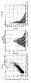
- Fig. 3(a) The synchronous distribution chart representing the relationship between the cube root voltage of Si (horizontal axis) and the cube root voltage of Al (vertical axis) is shown in Fig. 3(a) .
- the gradient of the line made so as to approximate the group of synchronized particles was 1.194.
- the accidental errors were calculated in the method described earlier, and they are shown in Fig. 3(b) in the form of an error histogram.
- the absolute deviation of accidental errors which is a measure of the variance of the accidental errors, was 0.082 as indicated in Table 1.
- Fig. 3(c) is the particle size distribution chart for Al.
- Fig. 4(a) The synchronous distribution chart representing the relationship between the cube root voltage of Si (horizontal axis) and the cube root voltage of Sr (vertical axis) is shown in Fig. 4(a) .
- the gradient of the line made so as to approximate the group of synchronized particles was 1.763.
- the accidental errors were calculated in the method described earlier, and they are shown in Fig. 4(b) in the form of an error histogram.
- the absolute deviation of accidental errors which is a measure of the variance of the accidental errors, was 0.101 as indicated in Table 1.
- Fig. 4(c) is the particle size distribution chart for Sr.
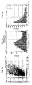
- Fig. 5(a) The synchronous distribution chart representing the relationship between the cube root voltage of Si (horizontal axis) and the cube root voltage of Ca (vertical axis) is shown in Fig. 5(a) .
- the gradient of the line made so as to approximate the group of synchronized particles was 1.789.
- the accidental errors were calculated in the method described earlier, and they are shown in Fig. 5(b) in the form of an error histogram.
- the absolute deviation of accidental errors which is a measure of the variance of the accidental errors, was 0.113 as indicated in Table 1.
- Fig. 5(c) is the particle size distribution chart for Ca.
- Fig. 6(a) The synchronous distribution chart representing the relationship between the cube root voltage of Si (horizontal axis) and the cube root voltage of Eu (vertical axis) is shown in Fig. 6(a) .
- the gradient of the line made so as to approximate the group of synchronized particles was 0.972.
- the accidental errors were calculated in the method described earlier, and they are shown in Fig. 6(b) in the form of an error histogram.
- the absolute deviation of the accidental errors which is a measure of the variance of the accidental errors, was 0.128 as indicated in Table 1.
- Fig. 6(c) is the particle size distribution chart for Eu.
- Fig. 7 is the particle size distribution chart for Si.
- the particle analyzer used had four spectrometers (ch1 to ch4) with different wavelength characteristics.
- the spectrometer recommended by the manufacturer was used in the analysis described above.
- the number of the used spectrometer is indicated in Figs. 3 to 7 as, for example, (ch1). This applies also to Figs. 10 to 13 .
- the alloy plate obtained in Example 1 was ground under nitrogen flow until the resulting alloy powder had a median diameter D 50 of 20 ⁇ m, and then the alloy powder were bedded on a tray made of boron nitride.
- the tray was settled in a hot isostatic pressing apparatus (HIP) and then the HIP was evacuated until the inside pressure was reduced to 5 ⁇ 10 -1 Pa, heated to 300°C, and thereafter evacuated once again at 300°C for one hour. After that, the following cycle was repeated twice: the apparatus was filled with nitrogen until the inside pressure rose to 1 MPa, cooled, evacuated until the inside pressure dropped to 0.1 Pa, and then filled with nitrogen until the inside pressure rose to 1 MPa once again.
- HIP hot isostatic pressing apparatus
- the inside pressure of the apparatus was maintained at 190 MPa while the alloy powder were heated to 1900°C at a heating rate of 10°C/min.
- the alloy powder were further heated at this temperature for one hour, yielding the intended composite nitride phosphor, Sr 0.792 Ca 0.2 AlSiN 3 :Eu 0.008 .
- the powder X-ray diffractometry of the obtained phosphor demonstrated that the phosphor had an orthorhombic phase structure formed, which is also observed in Ca A lSiN 3 .
- the emission spectrum of this phosphor was recorded with an excitation wavelength of 465 nm. Assuming that the light emission intensity of the phosphor obtained in Comparative Example 3 described later was 100%, the relative peak emission intensity calculated from the obtained spectrum was 100%. Also, assuming that the brightness of the phosphor obtained in Comparative Example 3 was 100%, the relative brightness of this reference example was 186%. The emission wavelength was 630 nm.
- the emission spectrum of the phosphor was measured using a 150-W xenon lamp as an excitation light source and a fluorometer (manufactured by JASCO Corporation) equipped with a multi-channel CCD detector C7041 (manufactured by Hamamatsu Photonics K.K.) as a spectrometer.
- the light emitted from the excitation light source was allowed to pass through a grating monochromator with a focal distance of 10 cm and then through a fiber optic so that the phosphor was irradiated with excitation light having a wavelength of 465 nm only.
- the light emitted from the phosphor as the result of the irradiation with the excitation light was separated by another grating monochromator with a focal distance of 25 cm, and the spectrometer measured the intensity of the light by wavelength over the wavelength range of 300 nm to 800 nm. After the signal processing of the obtained intensity, such as the sensitivity correction using a PC, the emission spectrum was obtained.
- composition analysis of this alloy in ICP spectrometry demonstrated that the composition of the alloy was identical to that specified at the weighing step. Therefore, Eu and the other elements seemed to be uniformly distributed.
- FIG. 8 A X-ray powder diffraction pattern of the obtained alloy is shown in Fig. 8 .
- the indexed broken lines represent the peaks of Sr(Si 0.5 Al 0.5 ) 2
- the other broken lines represent the peaks of Al 2 Si 2 Sr. This applies also to Fig. 9 .
- the obtained alloy had the main phase the X-ray powder diffraction pattern of which was similar to that of Sr(Si 0.5 Al 0.5 ) 2 included.
- Fig. 8 also demonstrated that the obtained alloy was a single-phase alloy.
- Example 2 The alloy prate obtained in Example 2 was ground and calcined under the same conditions as those used in Reference Example 1. The moiety without the light emission capability of the obtained nitride was removed therefrom, and the remaining moiety was washed in water and dried. As a result, the phosphor Sr 0.992 AlSiN 3 :Eu 0.008 was obtained.
- the powder X-ray diffractometry of the obtained phosphor demonstrated that the phosphor had an orthorhombic phase structure formed, which is also observed in CaAlSiN 3 .
- the emission spectrum of this phosphor was measured in the same method as that used in Reference Example 1.
- the relative peak emission intensity, the relative brightness and the wavelength of emission peak were 96%, 239% and 609 nm, respectively.
- composition analysis of this alloy in ICP spectrometry demonstrated that the composition of the alloy was identical to that specified at the weighing step. Therefore, Eu and the other elements seemed to be uniformly distributed.
- the obtained alloy had the main phase the X-ray powder diffraction pattern of which was similar to that of Sr(Si 0.5 Al 0.5 ) 2 included.
- the X-ray powder diffraction pattern also demonstrated that the obtained alloy was a single-phase alloy.
- the powder X-ray diffractometry of the obtained phosphor demonstrated that the phosphor had an orthorhombic phase structure formed, which is also observed in CaAlSiN 3 .
- the emission spectrum of this phosphor was measured in the same method as that used in Reference Example 1.
- the relative peak emission intensity, the relative brightness and the wavelength of emission peak were 85%, 128% and 641 nm, respectively.
- the obtained alloy had the main phase the X-ray powder diffraction pattern of which was similar to that of Sr(Si 0.5 Al 0.5 ) included.
- the X-ray powder diffraction pattern also demonstrated that the obtained alloy was a single-phase alloy.
- Example 4 The alloy prate obtained in Example 4 was ground and calcined under the same conditions as those used in Reference Example 1 so as to form the phosphor Sr 0.694 Ca 0.3 AlSiN 3 :Eu 0.006 .
- the powder X-ray diffractometry of the obtained phosphor demonstrated that the phosphor had an orthorhombic phase structure formed, which is also observed in CaAlSiN 3 .
- the emission spectrum of this phosphor was measured in the same method as that used in Reference Example 1.
- the relative peak emission intensity, the relative brightness and the wavelength of emission peak were 92%, 173% and 631 nm, respectively.
- the obtained alloy ingot has the main phase the X-ray powder diffraction pattern of which is identified as that of SrSi 2 included and contains a small amount of the Si phase.
- the X-ray powder diffraction pattern demonstrates that the obtained alloy contains small amounts of SrSi, Sr 4 Si 7 , Sr 5 Si 3 and/or Sr 7 Si phases besides the main phase.
- the alloy ingot obtained in Example 5 is ground in an alumina mortar placed under a nitrogen atmosphere, and then screened with a 53- ⁇ m mesh.
- the obtained alloy powder are placed in a vessel made of boron nitride.
- the apparatus is evacuated to vacuum and then filled with nitrogen until the inside pressure rises to 0.92 MPa.
- the alloy powder are heated to 1800°C and maintained at this temperature for two hours, yielding the phosphor, Sr 1.984 Si 5 N 8 :Ei 0.016 .
- the obtained phosphor exhibits the X-ray powder diffraction pattern of the high-purity Sr 2 Si 5 N 8 phase.
- the emission spectrum of this phosphor measured in the same method as that used in Reference Example 1 has the emission peak in the wavelength range of 610 nm to 620 nm.
- the peak emission intensity observed is equivalent to that of Comparative Example 3.
- Example 6 Using the alloy obtained in Example 6, a phosphor is produced under the same conditions as those used in Reference Example 5.
- the obtained phosphor is represented by Sr 1.96 Si 5 N 8 :Eu 0.04 , which exhibits the X-ray powder diffraction pattern of the high-purity Sr 2 Si 5 N 8 phase.
- the emission spectrum of this phosphor measured in the same method as that used in Reference Example 1 has the emission peak at a wavelength of approximately 630 nm.
- the peak emission intensity observed is equivalent to that of Comparative Example 3.
- the X-ray powder diffraction pattern of the obtained alloy is shown in Fig. 9 .
- Example 2 Compared with Comparative Example 2 ( Fig. 9 ), Example 2 ( Fig. 8 ) is clearly improved in terms of crystallinity and purity as an intermetallic compound.
- Fig. 10(a) The synchronous distribution chart representing the relationship between the cube root voltage of Si (horizontal axis) and the cube root voltage of Al (vertical axis) is shown in Fig. 10(a) .
- the gradient of the line made so as to approximate the group of synchronized particles was 1.040.
- the accidental errors were calculated in the method described earlier, and they are shown in Fig. 10(b) in the form of an error histogram.
- the absolute deviation of accidental errors which is a measure of the variance of the accidental errors, was 0.206 as indicated in Table 1.
- Fig. 10(c) is the particle size distribution chart for Al.
- Fig. 11 (a) The synchronous distribution chart representing the relationship between the cube root voltage of Si (horizontal axis) and the cube root voltage of Ca (vertical axis) is shown in Fig. 11 (a) .
- the gradient of the line made so as to approximate the group of synchronized particles was 1.355.
- the accidental errors were calculated in the method described earlier, and they are shown in Fig. 11(b) in the form of an error histogram.
- the absolute deviation of accidental errors which is a measure of the variance of the accidental errors, was 0.227 as indicated in Table 1.
- Fig. 11(c) is the particle size distribution chart for Ca.
- Fig. 12(a) The synchronous distribution chart representing the relationship between the cube root voltage of Si (horizontal axis) and the cube root voltage of Eu (vertical axis) is shown in Fig. 12(a) .
- the gradient of the line made so as to approximate the group of synchronized particles was 0.694.
- the accidental errors were calculated in the method described earlier, and they are shown in Fig. 12(b) in the form of an error histogram.
- the absolute deviation of accidental errors which is a measure of the variance of the accidental errors, was 0.445 as indicated in Table 1.
- Fig. 12(c) is the particle size distribution chart for Eu.
- Fig. 13 is the particle size distribution chart for Si.
- the obtained phosphor raw material was bedded in a crucible made of boron nitride, and the crucible was settled in an atmosphere-heating furnace. The furnace was evacuated until the inside pressure was reduced to 1 ⁇ 10 -2 Pa and then filled with nitrogen until the inside pressure rose to 0.1 MPa. Subsequently, the phosphor raw material was heated to 1600°C and maintained at this temperature for five hours, yielding the phosphor.
- the phosphor raw material according to the present invention represented by Example 1
- the difference in the absolute deviation of accidental errors between Example 1 and Comparative Example 3 is particularly significant with respect to Eu used as the activator element M 1 .
- the phosphor raw material according to the present invention probably enables distributing its constituent elements uniformly in itself and producing phosphors with markedly high brightness and other excellent light emission properties.
Landscapes
- Chemical & Material Sciences (AREA)
- Engineering & Computer Science (AREA)
- Materials Engineering (AREA)
- Organic Chemistry (AREA)
- Inorganic Chemistry (AREA)
- Mechanical Engineering (AREA)
- Metallurgy (AREA)
- Luminescent Compositions (AREA)
Applications Claiming Priority (2)
| Application Number | Priority Date | Filing Date | Title |
|---|---|---|---|
| JP2006053093 | 2006-02-28 | ||
| PCT/JP2007/053620 WO2007099942A1 (fr) | 2006-02-28 | 2007-02-27 | Produit de depart phosphore et procede de production d'un alliage pour produit de depart phosphore |
Publications (2)
| Publication Number | Publication Date |
|---|---|
| EP1990396A1 true EP1990396A1 (fr) | 2008-11-12 |
| EP1990396A4 EP1990396A4 (fr) | 2011-05-11 |
Family
ID=38459046
Family Applications (1)
| Application Number | Title | Priority Date | Filing Date |
|---|---|---|---|
| EP07737422A Withdrawn EP1990396A4 (fr) | 2006-02-28 | 2007-02-27 | Produit de depart phosphore et procede de production d'un alliage pour produit de depart phosphore |
Country Status (6)
| Country | Link |
|---|---|
| US (1) | US20090134359A1 (fr) |
| EP (1) | EP1990396A4 (fr) |
| KR (1) | KR20080097174A (fr) |
| CN (1) | CN101360805A (fr) |
| TW (1) | TW200804564A (fr) |
| WO (1) | WO2007099942A1 (fr) |
Cited By (1)
| Publication number | Priority date | Publication date | Assignee | Title |
|---|---|---|---|---|
| US8123980B2 (en) | 2006-05-19 | 2012-02-28 | Mitsubishi Chemical Corporation | Nitrogen-containing alloy and method for producing phosphor using same |
Families Citing this family (7)
| Publication number | Priority date | Publication date | Assignee | Title |
|---|---|---|---|---|
| JP5332136B2 (ja) * | 2006-09-29 | 2013-11-06 | 三菱化学株式会社 | 窒素含有合金、及びそれを使用した蛍光体の製造方法 |
| EP2604576B1 (fr) * | 2011-12-12 | 2016-03-09 | BK Giulini GmbH | Procédé de fabrication de lithium-métal-phosphate |
| KR101445815B1 (ko) * | 2012-12-12 | 2014-09-29 | 희성금속 주식회사 | 형광체 원료용 합금의 제조 방법 |
| TWI494414B (zh) * | 2012-12-22 | 2015-08-01 | Chi Mei Corp | 螢光體及發光裝置 |
| WO2015001860A1 (fr) * | 2013-07-03 | 2015-01-08 | 電気化学工業株式会社 | Luminophore et dispositif électroluminescent |
| JP6528418B2 (ja) | 2014-01-29 | 2019-06-12 | 日亜化学工業株式会社 | 蛍光体及びこれを用いた発光装置 |
| DE102016200324A1 (de) * | 2016-01-14 | 2017-07-20 | MTU Aero Engines AG | Verfahren zum Ermitteln einer Konzentration wenigstens eines Werkstoffs in einem Pulver für ein additives Herstellverfahren |
Family Cites Families (14)
| Publication number | Priority date | Publication date | Assignee | Title |
|---|---|---|---|---|
| US6080954A (en) * | 1996-12-27 | 2000-06-27 | Neturen Co., Ltd | Heat treatment method and apparatus using thermal plasma, and heat treated substance produced thereby |
| DE10147040A1 (de) * | 2001-09-25 | 2003-04-24 | Patent Treuhand Ges Fuer Elektrische Gluehlampen Mbh | Beleuchtungseinheit mit mindestens einer LED als Lichtquelle |
| WO2003080764A1 (fr) * | 2002-03-22 | 2003-10-02 | Nichia Corporation | Phosphore de nitrure, procede de preparation de phosphore de nitrure et diode electroluminescente |
| JP4656816B2 (ja) * | 2002-06-27 | 2011-03-23 | 日亜化学工業株式会社 | 発光装置 |
| JP4979187B2 (ja) | 2003-07-24 | 2012-07-18 | 東洋アルミニウム株式会社 | 窒化アルミニウム系蛍光体及びその製造方法 |
| TWI359187B (en) * | 2003-11-19 | 2012-03-01 | Panasonic Corp | Method for preparing nitridosilicate-based compoun |
| JP3837588B2 (ja) * | 2003-11-26 | 2006-10-25 | 独立行政法人物質・材料研究機構 | 蛍光体と蛍光体を用いた発光器具 |
| TWI262609B (en) * | 2004-02-27 | 2006-09-21 | Dowa Mining Co | Phosphor and manufacturing method thereof, and light source, LED using said phosphor |
| JP2005298721A (ja) * | 2004-04-14 | 2005-10-27 | Nichia Chem Ind Ltd | 酸窒化物蛍光体及びそれを用いた発光装置 |
| JP2007534609A (ja) * | 2004-04-27 | 2007-11-29 | アリゾナ ボード オブ リージェンツ | 高度発光ドープ金属窒化物粉末を合成するための方法 |
| JP4484626B2 (ja) | 2004-08-13 | 2010-06-16 | 富士フイルム株式会社 | バイオセンサー |
| JP5130640B2 (ja) * | 2005-04-01 | 2013-01-30 | 三菱化学株式会社 | 蛍光体の製造方法 |
| EP2781575A3 (fr) * | 2005-04-01 | 2015-02-18 | Mitsubishi Chemical Corporation | Poudre d'alliage pour précurseur de matériau fonctionnel inorganique et phosphore |
| WO2008032812A1 (fr) * | 2006-09-15 | 2008-03-20 | Mitsubishi Chemical Corporation | Substance luminescente, son procédé de fabrication, composition contenant la substance luminescente, dispositif émettant de la lumière, dispositif d'affichage d'images et dispositif d'éclairage |
-
2007
- 2007-02-27 TW TW096106702A patent/TW200804564A/zh unknown
- 2007-02-27 US US12/279,345 patent/US20090134359A1/en not_active Abandoned
- 2007-02-27 WO PCT/JP2007/053620 patent/WO2007099942A1/fr not_active Ceased
- 2007-02-27 EP EP07737422A patent/EP1990396A4/fr not_active Withdrawn
- 2007-02-27 KR KR1020087013939A patent/KR20080097174A/ko not_active Withdrawn
- 2007-02-27 CN CNA2007800014977A patent/CN101360805A/zh active Pending
Cited By (2)
| Publication number | Priority date | Publication date | Assignee | Title |
|---|---|---|---|---|
| US8123980B2 (en) | 2006-05-19 | 2012-02-28 | Mitsubishi Chemical Corporation | Nitrogen-containing alloy and method for producing phosphor using same |
| US8636920B2 (en) | 2006-05-19 | 2014-01-28 | Mitsubishi Chemical Corporation | Nitrogen-containing alloy and method for producing phosphor using same |
Also Published As
| Publication number | Publication date |
|---|---|
| CN101360805A (zh) | 2009-02-04 |
| WO2007099942A1 (fr) | 2007-09-07 |
| KR20080097174A (ko) | 2008-11-04 |
| US20090134359A1 (en) | 2009-05-28 |
| TW200804564A (en) | 2008-01-16 |
| EP1990396A4 (fr) | 2011-05-11 |
Similar Documents
| Publication | Publication Date | Title |
|---|---|---|
| JP5206941B2 (ja) | 蛍光体とその製造方法および発光器具 | |
| JP3921545B2 (ja) | 蛍光体とその製造方法 | |
| EP1997865B1 (fr) | Luminophore, procede de production et dispositif electroluminescent | |
| EP1990396A1 (fr) | Produit de depart phosphore et procede de production d'un alliage pour produit de depart phosphore | |
| US8460580B2 (en) | Alloy powder for raw material of inorganic functional material and phosphor | |
| JP5292723B2 (ja) | 蛍光体の製造方法 | |
| KR100987086B1 (ko) | 형광체와 그 제조 방법 및 발광 기구 | |
| JP5181492B2 (ja) | 蛍光体原料及び蛍光体原料用合金の製造方法 | |
| JP2005008794A (ja) | サイアロン蛍光体とその製造方法 | |
| JP2007262417A (ja) | 蛍光体 | |
| WO2019188630A1 (fr) | CORPS FLUORESCENT α-SIALON ET DISPOSITIF ÉLECTROLUMINESCENT | |
| JP3914991B2 (ja) | サイアロン蛍光体の製造方法 | |
| WO2019188631A1 (fr) | CORPS FLUORESCENT DE β-SIALON ET DISPOSITIF ÉLECTROLUMINESCENT | |
| EP2808374B1 (fr) | Luminophore, son procédé de fabrication et son utilisation | |
| JP3975451B2 (ja) | 蛍光体を用いた照明器具および画像表示装置 | |
| EP4194528A1 (fr) | Luminophore au nitrure et procédé de fabrication s'y rapportant | |
| JP5239176B2 (ja) | 蛍光体用合金粉末及びその製造方法 | |
| JP5292724B2 (ja) | 窒化物を母体とする蛍光体の製造方法 | |
| JP2025037292A (ja) | 蛍光体 | |
| JP2011068956A (ja) | 蛍光体合成用合金の製造方法 |
Legal Events
| Date | Code | Title | Description |
|---|---|---|---|
| PUAI | Public reference made under article 153(3) epc to a published international application that has entered the european phase |
Free format text: ORIGINAL CODE: 0009012 |
|
| 17P | Request for examination filed |
Effective date: 20080729 |
|
| AK | Designated contracting states |
Kind code of ref document: A1 Designated state(s): DE |
|
| RBV | Designated contracting states (corrected) |
Designated state(s): DE |
|
| RIC1 | Information provided on ipc code assigned before grant |
Ipc: C22C 28/00 20060101ALI20110331BHEP Ipc: C09K 11/77 20060101ALI20110331BHEP Ipc: C09K 11/64 20060101AFI20071002BHEP Ipc: C09K 11/08 20060101ALI20110331BHEP |
|
| A4 | Supplementary search report drawn up and despatched |
Effective date: 20110411 |
|
| STAA | Information on the status of an ep patent application or granted ep patent |
Free format text: STATUS: THE APPLICATION IS DEEMED TO BE WITHDRAWN |
|
| 18D | Application deemed to be withdrawn |
Effective date: 20111109 |