EP1990444A2 - Method for after-treatment of welded connections - Google Patents
Method for after-treatment of welded connections Download PDFInfo
- Publication number
- EP1990444A2 EP1990444A2 EP08007714A EP08007714A EP1990444A2 EP 1990444 A2 EP1990444 A2 EP 1990444A2 EP 08007714 A EP08007714 A EP 08007714A EP 08007714 A EP08007714 A EP 08007714A EP 1990444 A2 EP1990444 A2 EP 1990444A2
- Authority
- EP
- European Patent Office
- Prior art keywords
- workpiece
- weld
- cover layer
- aluminum
- workpieces
- Prior art date
- Legal status (The legal status is an assumption and is not a legal conclusion. Google has not performed a legal analysis and makes no representation as to the accuracy of the status listed.)
- Withdrawn
Links
Images
Classifications
-
- C—CHEMISTRY; METALLURGY
- C23—COATING METALLIC MATERIAL; COATING MATERIAL WITH METALLIC MATERIAL; CHEMICAL SURFACE TREATMENT; DIFFUSION TREATMENT OF METALLIC MATERIAL; COATING BY VACUUM EVAPORATION, BY SPUTTERING, BY ION IMPLANTATION OR BY CHEMICAL VAPOUR DEPOSITION, IN GENERAL; INHIBITING CORROSION OF METALLIC MATERIAL OR INCRUSTATION IN GENERAL
- C23C—COATING METALLIC MATERIAL; COATING MATERIAL WITH METALLIC MATERIAL; SURFACE TREATMENT OF METALLIC MATERIAL BY DIFFUSION INTO THE SURFACE, BY CHEMICAL CONVERSION OR SUBSTITUTION; COATING BY VACUUM EVAPORATION, BY SPUTTERING, BY ION IMPLANTATION OR BY CHEMICAL VAPOUR DEPOSITION, IN GENERAL
- C23C24/00—Coating starting from inorganic powder
- C23C24/02—Coating starting from inorganic powder by application of pressure only
- C23C24/04—Impact or kinetic deposition of particles
Definitions
- the present invention relates to a method for the post-treatment of a weld on a workpiece in order to improve the mechanical properties of the weld.
- the problem is that in the area of the weld, tensile stresses form in the material of the weld itself as well as in the material of the adjacent workpieces. On the one hand, these tensile stresses can lead to a reduction in the strength of the material. On the other hand, due to the tensile stresses under load, formation of cracks in the area of the surface can occur which, on the one hand, further impair the strength of the weld seam and, on the other hand, accelerate the corrosion in this area.
- the aluminum workpieces that are to be welded often consist of an aluminum alloy with a coating of pure aluminum, the coating serving as a "sacrificial anode" to protect the aluminum alloy of the workpiece from corrosion to protect.
- this coating is destroyed by the welding process, so that in this area, the effect of the sacrificial anode is lost and the aluminum alloy of the workpieces is exposed here to a greater extent corrosion attacks.
- the area of the weld is exposed by the mixing of the material of the coating base and thus an increased risk of corrosion. It would therefore further be desirable if, after the production of a weld on such workpieces, a sacrificial anode material would again be present in the area of the weld seam.
- this object is achieved in that a cover layer is applied to the weld on a workpiece by cold gas spraying.
- the weld can be formed before the application of the cover layer by any known from the prior art welding method, in particular gas welding, arc welding and laser welding come into question.
- the weld can serve the purpose of connecting two components to a single workpiece or, on the other hand, of closing openings in a workpiece.
- powdered material from which the top layer is formed is placed within a nozzle in a gas jet, so that the particles are accelerated to high speeds, typically at speeds above the speed of sound, and thus receive high kinetic energy. If the particles impinge on the workpiece to be coated or the surface of the weld, they form a dense, firmly adhering layer, as it due to the high kinetic energy and the resulting heat release when hitting the workpiece to a liability of the particles themselves and also comes on the workpiece.
- details for cold gas spraying is incidentally on the DE 101 26 100 A1 directed
- cold-gas-sprayed layers have compressive stress after being applied to a workpiece.
- compression stresses are introduced into the workpiece itself during the coating process.
- the size of the particles used in the cold gas spraying is between 10 and 60 ⁇ m, and preferably between 20 and 45 ⁇ m, it has been shown that good results can be achieved in terms of reducing the tensile stresses in the weld and the workpiece.
- the method according to the invention has proven to be particularly advantageous with regard to workpieces whose material comprises aluminum or aluminum alloys. But it is also possible that the inventive method is applied to workpieces made of titanium or titanium alloys. In addition, the method according to the invention can be applied to workpieces made of steel, it being possible to restore the originally good corrosion properties in the region of the weld, in particular when galvanized steel workpieces are aftertreated. Furthermore, the method can also be applied to copper and copper alloys.
- the material of the cover layer behaves anodically to the material of the weld.
- the cover layer not only counteracts the tensile stresses, but also serves as a sacrificial anode with respect to the weld so that the material of the weld is not exposed to corrosion.
- the material of the cover layer can also be chosen so that it also behaves anodically to the material of the workpiece and thus also acts as a sacrificial anode against this.
- the properties can be restored, which, if the workpiece is provided with a coating designed as a sacrificial anode, were present before the formation of the weld.
- the materials may be selected in such a way that the material of the workpieces comprises an aluminum alloy and the cover layer consists of aluminum, wherein the Workpieces in a further preferred manner also have a coating of aluminum.
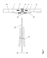
- a workpiece 1 with a weld seam 3 is shown, wherein the weld seam 3 can be formed by known welding methods, for example gas-melt welding, arc welding and laser welding.
- the material of the workpiece 1 is an aluminum alloy, wherein on the workpiece 1 there is still a coating 5 of pure aluminum which serves as a sacrificial anode and which is interrupted in the region of the weld seam 3 due to the welding process is.
- the thickness of the workpiece 1 may be between 0.5 and 10 mm in the example described here, and the coating 5 may be multi-layered.
- workpieces made of copper or titanium and titanium or copper alloys are used.
- workpieces made of steel it being possible in particular when galvanized steel workpieces to be treated to restore the originally good corrosion properties in the area of the weld seam.
- the material of the weld 3 is formed due to the welding process of the material of the workpiece 1 itself and that of the coating 5 and thus less noble than the workpiece material. As a result, the weld 3 is initially more susceptible to corrosion than the rest of the workpiece 1 Weld 3 and the adjacent to her area of the workpiece 1 before coating under tensile stresses, so that the strength and corrosion resistance, as explained above, are reduced here (see arrows 7).
- the workpiece 1 is arranged at a distance of between 10 and 60 mm in front of a cold gas spraying nozzle 9, which is shown here only schematically.
- particles having a size between 10 and 60 ⁇ m and preferably between 20 and 45 ⁇ m in a gas stream 11 are typically accelerated to speeds above the speed of sound.
- the material of the particles in the present embodiment is aluminum, and nitrogen is used as the process gas, wherein the process gas can be preheated and has a pressure between 5 to 60 bar and preferably between 20 to 40 bar.
- the particles in the gas stream 9 strike the workpiece 1 in the area of the weld seam 3 and form a cover layer 13 over the weld seam 3.
- the gas stream 9 has a typical diameter of 2 to 10 mm, so preferably several times in lines over the range of Weld 3 is applied to the cover layer 13 of pure aluminum with a thickness of 0.05 to 10 mm applied to the region of the weld 3.
- cover layer 13 according to the invention to the weld seam 5 by means of cold gas spraying results in adhesion of the particles to one another in the cover layer 13 and on the workpiece 1 due to the high kinetic energy of the particles and the resulting heat release upon impact with the workpiece 1 comes.
- 13 compressive stresses (arrow 15) are built up, inter alia, by the constant impact of other solid particles in the cover layer.
- the cover layer 13 is made of pure aluminum in the preferred embodiment described here, the cover layer 13 behaves anodically both to the workpieces 1 and to the weld 3, so that also in this way the corrosion resistance of the welded workpiece is improved.
Landscapes
- Chemical & Material Sciences (AREA)
- Chemical Kinetics & Catalysis (AREA)
- Engineering & Computer Science (AREA)
- Materials Engineering (AREA)
- Mechanical Engineering (AREA)
- Metallurgy (AREA)
- Organic Chemistry (AREA)
- Arc Welding In General (AREA)
- Laser Beam Processing (AREA)
- Coating By Spraying Or Casting (AREA)
Abstract
Dargestellt und beschrieben ist ein Verfahren zur Nachbehandlung von Schweißverbindungen. Die Aufgabe, ein Verfahren zur Nachbehandlung einer Schweißnaht bereitzustellen, durch welches die Zugspannungen im Bereich der Schweißnaht vermindert werden, wird dadurch gelöst, dass auf die Schweißnaht an einem Werkstück eine Deckschicht durch Kaltgasspritzen aufgebracht wird.

Description
Die vorliegende Erfindung betrifft ein Verfahren zur Nachbehandlung einer Schweißnaht an einem Werkstück, um die mechanischen Eigenschaften der Schweißnaht zu verbessern.The present invention relates to a method for the post-treatment of a weld on a workpiece in order to improve the mechanical properties of the weld.
Insbesondere im Bereich des Flugzeugbaus, wo in sehr großem Umfang Aluminium verwendet wird, gibt es das Bestreben, aus diesem Werkstoff oder seinen Legierungen bestehende Werkstücke statt durch Nieten über Schweißnähte miteinander zu verbinden, da dies mit einer Gewichtsersparnis verbunden ist, was gerade in diesem Bereich hochrelevant ist.Particularly in the field of aircraft construction, where aluminum is used to a very great extent, there is an endeavor to connect workpieces made of this material or its alloys to one another instead of by riveting over welds, since this is associated with a weight saving, which is precisely in this area highly relevant.
Wie bei allen Metallen besteht auch bei Aluminium bei der Herstellung einer Schweißnaht, gleich welches thermische Schweißverfahren gewählt wird, das Problem, dass sich im Bereich der Schweißnaht Zugspannungen im Material der Schweißnaht selbst wie auch im Material der benachbarten Werkstücke ausbilden. Diese Zugspannungen können einerseits dazu führen, dass die Festigkeit des Materials vermindert wird. Andererseits kann es aufgrund der Zugspannungen unter Belastung zu einer Bildung von Rissen im Bereich der Oberfläche kommen, die zum einen die Festigkeit der Schweißnaht weiter beeinträchtigen und zum anderen die Korrosion in diesem Bereich beschleunigen.As with all metals, in the manufacture of a weld, regardless of which thermal welding process is chosen, the problem is that in the area of the weld, tensile stresses form in the material of the weld itself as well as in the material of the adjacent workpieces. On the one hand, these tensile stresses can lead to a reduction in the strength of the material. On the other hand, due to the tensile stresses under load, formation of cracks in the area of the surface can occur which, on the one hand, further impair the strength of the weld seam and, on the other hand, accelerate the corrosion in this area.
Um das Problem der Zugspannungen zu beseitigen, ist es möglich, die geschweißten Werkstücke auszulagern, also eine Temperaturbehandlung durchzuführen. Wenn die Werkstücke jedoch eine bestimmte Größe überschreiten, ist eine solche Behandlung nicht mehr durchführbar. Des Weiteren ergibt sich beim Auslagern das Problem, dass sich die Werkstücke dabei möglicherweise verziehen, was ebenfalls unerwünscht ist. Schließlich scheidet eine thermische Nachbehandlung bei bereits ausgehärteten Materialien aus.In order to eliminate the problem of tensile stresses, it is possible to outsource the welded workpieces, so perform a temperature treatment. However, if the workpieces exceed a certain size, such a treatment is no longer feasible. Furthermore, there is the problem during removal, that the workpieces may warp, which is also undesirable. Finally, a thermal after-treatment of already cured materials is eliminated.
Außerdem erweist es sich als Problem, dass die Aluminium-Werkstücke, die verschweißt werden sollen, häufig aus einer Aluminium-Legierung mit einer Beschichtung aus reinem Aluminium bestehen, wobei die Beschichtung als "Opferanode" dient, um die Aluminium-Legierung des Werkstücks vor Korrosion zu schützen. Im Bereich der Schweißnaht wird diese Beschichtung durch den Schweißprozess zerstört, sodass in diesem Bereich auch die Wirkung der Opferanode verloren geht und die Aluminium-Legierung der Werkstücke hier in verstärktem Maße Korrosionsangriffen ausgesetzt ist. Außerdem wird der Bereich der Schweißnaht durch das Einmischen des Materials der Beschichtung unedler und damit einem erhöhten Korrosionsrisiko ausgesetzt. Es wäre daher weiterhin wünschenswert, wenn nach der Herstellung einer Schweißnaht an derartigen Werkstücken auch im Bereich der Schweißnaht wieder ein Opferanodenmaterial vorhanden wäre.In addition, it proves to be a problem that the aluminum workpieces that are to be welded often consist of an aluminum alloy with a coating of pure aluminum, the coating serving as a "sacrificial anode" to protect the aluminum alloy of the workpiece from corrosion to protect. In the area of the weld, this coating is destroyed by the welding process, so that in this area, the effect of the sacrificial anode is lost and the aluminum alloy of the workpieces is exposed here to a greater extent corrosion attacks. In addition, the area of the weld is exposed by the mixing of the material of the coating base and thus an increased risk of corrosion. It would therefore further be desirable if, after the production of a weld on such workpieces, a sacrificial anode material would again be present in the area of the weld seam.
Daher ist es die Aufgabe der vorliegenden Erfindung, ein Verfahren zur Nachbehandlung einer Schweißnaht bereitzustellen, durch welches die Zugspannungen im Bereich der Schweißnaht vermindert werden.It is therefore the object of the present invention to provide a method for the after-treatment of a weld, by means of which the tensile stresses in the area of the weld are reduced.
Erfindungsgemäß wird diese Aufgabe dadurch gelöst, dass auf die Schweißnaht an einem Werkstück eine Deckschicht durch Kaltgasspritzen aufgebracht wird.According to the invention, this object is achieved in that a cover layer is applied to the weld on a workpiece by cold gas spraying.
Dabei kann die Schweißnaht vor dem Aufbringen der Deckschicht durch beliebige, aus dem Stand der Technik bekannte Schweißverfahren gebildet werden, wobei insbesondere Gasschmelzschweißen, Lichtbogenschweißen und Laserschweißen in Frage kommen. Die Schweißnaht kann zum einen den Zweck erfüllen, zwei Bauteile zu einem einzigen Werkstück zu verbinden, oder zum anderen dazu dienen, Öffnungen in einem Werkstück zu schließen.In this case, the weld can be formed before the application of the cover layer by any known from the prior art welding method, in particular gas welding, arc welding and laser welding come into question. On the one hand, the weld can serve the purpose of connecting two components to a single workpiece or, on the other hand, of closing openings in a workpiece.
Beim Kaltgasspritzen wird pulverförmiges Material, aus dem die Deckschicht gebildet wird, innerhalb einer Düse in einen Gasstrahl gegeben, sodass die Partikel auf hohe Geschwindigkeiten, typischerweise auf Geschwindigkeiten oberhalb der Schallgeschwindigkeit, beschleunigt werden und damit eine hohe kinetische Energie erhalten. Wenn die Partikel auf das zu beschichtende Werkstück bzw. die Oberfläche der Schweißnaht auftreffen, bilden sie eine dichte, fest haftende Schicht, da es aufgrund der hohen kinetischen Energie und der daraus resultierenden Wärmefreigabe beim Auftreffen auf das Werkstück zu einer Haftung der Partikel untereinander und auch an dem Werkstück kommt. Im Hinblick auf Details zum Kaltgasspritzen wird im Übrigen auf die
Durch den ständigen Aufprall weiterer fester Partikel weisen kaltgasgespritzte Schichten nach dem Aufbringen auf ein Werkstück Druckspannung auf. Außerdem werden bei dem Beschichtungsprozess in das Werkstück selbst Druckspannungen eingebracht.As a result of the constant impact of further solid particles, cold-gas-sprayed layers have compressive stress after being applied to a workpiece. In addition, compression stresses are introduced into the workpiece itself during the coating process.
Dadurch ergibt sich die Möglichkeit, durch das Aufbringen einer kaltgasgespritzten Schicht auf die Oberfläche einer zuvor gebildeten Schweißnaht die Zugspannungen darin zu kompensieren und damit die Festigkeit zu erhöhen. Auf diese Weise wird außerdem die Neigung zur Rissbildung stark zu vermindert, sodass auf diese Weise die Korrosionsbeständigkeit der Schweißnaht verbessert wird.This results in the possibility of compensating for the tensile stresses therein by applying a cold gas-sprayed layer to the surface of a previously formed weld, thereby increasing the strength. In this way, the tendency for cracking is also greatly reduced, so that in this way the corrosion resistance of the weld is improved.
Wenn die Größe der beim Kaltgasspritzen verwendeten Partikel zwischen 10 und 60 µm und vorzugsweise zwischen 20 und 45 µm liegt, hat es sich gezeigt, dass sich gute Ergebnisse hinsichtlich der Reduzierung der Zugspannungen in der Schweißnaht und dem Werkstück erzielen lassen.If the size of the particles used in the cold gas spraying is between 10 and 60 μm, and preferably between 20 and 45 μm, it has been shown that good results can be achieved in terms of reducing the tensile stresses in the weld and the workpiece.
Auch wenn die vorliegende Erfindung nicht darauf beschränkt ist, so hat sich das erfindungsgemäße Verfahren als besonders vorteilhaft in Hinblick auf Werkstücke herausgestellt, deren Material Aluminium oder Aluminium-Legierungen umfasst. Es ist aber auch möglich, dass das erfindungsgemäße Verfahren bei Werkstücken aus Titan oder Titan-Legierungen angewandt wird. Darüber hinaus kann das erfindungsgemäße Verfahren bei Werkstücken aus Stahl angewandt werden, wobei insbesondere dann, wenn verzinkte Stahl-Werkstücke nachbehandelt werden, es möglich ist, im Bereich der Schweißnaht die ursprünglich guten Korrosionseigenschaften wiederherzustellen. Weiterhin kann das Verfahren auch bei Kupfer und Kupferlegierungen angewandt werden.Although the present invention is not limited thereto, the method according to the invention has proven to be particularly advantageous with regard to workpieces whose material comprises aluminum or aluminum alloys. But it is also possible that the inventive method is applied to workpieces made of titanium or titanium alloys. In addition, the method according to the invention can be applied to workpieces made of steel, it being possible to restore the originally good corrosion properties in the region of the weld, in particular when galvanized steel workpieces are aftertreated. Furthermore, the method can also be applied to copper and copper alloys.
Um die Korrosionsbeständigkeit der Schweißnaht weiter zu verbessern, hat es sich als vorteilhaft erwiesen, wenn sich das Material der Deckschicht anodisch zum Material der Schweißnaht verhält. In diesem Fall wirkt die Deckschicht nicht nur den Zugspannungen entgegen, sondern dient gleichzeitig als Opferanode in Bezug auf die Schweißnaht, sodass das Material der Schweißnaht keinen Angriffen durch Korrosion ausgesetzt ist.In order to further improve the corrosion resistance of the weld, it has proved to be advantageous if the material of the cover layer behaves anodically to the material of the weld. In this case, the cover layer not only counteracts the tensile stresses, but also serves as a sacrificial anode with respect to the weld so that the material of the weld is not exposed to corrosion.
In weiter bevorzugter Weise kann das Material der Deckschicht ferner so gewählt sein, dass es sich auch anodisch zu dem Material des Werkstücks verhält und damit auch diesem gegenüber als Opferanode wirkt. Bei einer derartigen Wahl des Materials der Deckschicht können insbesondere die Eigenschaften wiederhergestellt werden, die, sofern das Werkstück mit einer als Opferanode ausgebildeten Beschichtung versehen ist, vor der Bildung der Schweißnaht vorlagen.In a further preferred manner, the material of the cover layer can also be chosen so that it also behaves anodically to the material of the workpiece and thus also acts as a sacrificial anode against this. In such a choice of the material of the cover layer, in particular the properties can be restored, which, if the workpiece is provided with a coating designed as a sacrificial anode, were present before the formation of the weld.
Insbesondere können die Materialen in der Weise gewählt werden, dass das Material der Werkstücke eine Aluminium-Legierung aufweist und die Deckschicht aus Aluminium besteht, wobei die Werkstücke in weiter bevorzugter Weise auch eine Beschichtung aus Aluminium aufweisen.In particular, the materials may be selected in such a way that the material of the workpieces comprises an aluminum alloy and the cover layer consists of aluminum, wherein the Workpieces in a further preferred manner also have a coating of aluminum.
Im Folgenden wird die Erfindung anhand einer Zeichnung beschrieben, die lediglich ein bevorzugtes Ausführungsbeispiel darstellt. In der Zeichnung zeigt
- Fig.1
- schematisch den Aufbau einer Vorrichtung zur Durchführung des erfindungsgemäßen Verfahrens.
- Fig.1
- schematically the structure of a device for carrying out the method according to the invention.
In
Das Material der Schweißnaht 3 ist aufgrund des Schweißprozesses aus dem Material des Werkstücks 1 selbst und dem der Beschichtung 5 gebildet und damit unedler als das WerkstückMaterial. Dadurch ist die Schweißnaht 3 zunächst korrosionsanfälliger als das übrige Werkstück 1. Des weiteren steht die Schweißnaht 3 und der zu ihr benachbarte Bereich des Werkstücks 1 vor der Beschichtung unter Zugspannungen, sodass die Festigkeit und auch die Korrosionsbeständigkeit, wie eingangs erläutert, hier vermindert sind (siehe Pfeile 7).The material of the
Zur Durchführung des erfindungsgemäßen Verfahrens wird das Werkstück 1 in einem Abstand zwischen 10 und 60 mm vor einer Kaltgasspritzdüse 9 angeordnet, die hier nur schematisch dargestellt ist.For carrying out the method according to the invention, the
In der Kaltgasspritzdüse 9 werden Partikel mit einer Größe zwischen 10 und 60 µm und vorzugsweise zwischen 20 und 45 µm in einem Gasstrom 11 typischerweise auf Geschwindigkeiten oberhalb der Schallgeschwindigkeit beschleunigt. Bei dem Material der Partikel handelt es sich im vorliegenden Ausführungsbeispiel um Aluminium, und als Prozessgas wird Stickstoff verwendet, wobei das Prozessgas vorgeheizt werden kann und einen Druck zwischen 5 bis 60 bar und bevorzugt zwischen 20 bis 40 bar hat.In the cold
Die Partikel in dem Gasstrom 9 treffen in dem Bereich der Schweißnaht 3 auf das Werkstück 1 und bilden über der Schweißnaht 3 eine Deckschicht 13. Dabei hat der Gasstrom 9 einen typischen Durchmesser von 2 bis 10 mm, sodass bevorzugt mehrfach in Zeilen über den Bereich der Schweißnaht 3 gefahren wird, um die Deckschicht 13 aus reinem Aluminium mit einer Dicke von 0,05 bis 10 mm auf den Bereich der Schweißnaht 3 aufzubringen.The particles in the
Das erfindungsgemäße Aufbringen der Deckschicht 13 auf die Schweißnaht 5 mittels Kaltgasspritzens führt dazu, dass es aufgrund der hohen kinetischen Energie der Partikel und der daraus resultierenden Wärmefreigabe beim Auftreffen auf das Werkstück 1 zu einer Haftung der Partikel untereinander in der Deckschicht 13 und an dem Werkstück 1 kommt. Außerdem werden am Anfang des Beschichtungsprozesses in das Werkstück 1 selbst Druckspannungen eingebracht, durch die die nach dem Schweißen vorhandenen Zugspannungen 7 kompensiert werden. Danach werden u.a. durch den ständigen Aufprall weiterer fester Partikel in der Deckschicht 13 Druckspannungen (Pfeil 15) aufgebaut.The application of the
Dadurch ergibt sich die Möglichkeit, durch das Aufbringen einer kaltgasgespritzten Deckschicht 13 auf die Oberfläche einer zuvor gebildeten Schweißnaht 3 die Zugspannungen 7 darin zu kompensieren und damit die Festigkeit zu erhöhen. Auf diese Weise wird außerdem die Neigung zur Rissbildung stark zu vermindert, sodass auf diese Weise auch die Korrosionsbeständigkeit der Schweißnaht 3 verbessert wird.This results in the possibility of compensating for the tensile stresses 7 therein by applying a cold gas-sprayed
Da die Deckschicht 13 in dem hier beschriebenen bevorzugten Ausführungsbeispiel aus reinem Aluminium besteht, verhält sich die Deckschicht 13 anodisch sowohl zu den Werkstücken 1 als auch zu der Schweißnaht 3, sodass auch auf diesem Wege die Korrosionsbeständigkeit des geschweißten Werkstücks verbessert wird.Since the
Claims (11)
Applications Claiming Priority (1)
| Application Number | Priority Date | Filing Date | Title |
|---|---|---|---|
| DE102007021736A DE102007021736A1 (en) | 2007-05-09 | 2007-05-09 | Process for the aftertreatment of welded joints |
Publications (1)
| Publication Number | Publication Date |
|---|---|
| EP1990444A2 true EP1990444A2 (en) | 2008-11-12 |
Family
ID=39514641
Family Applications (1)
| Application Number | Title | Priority Date | Filing Date |
|---|---|---|---|
| EP08007714A Withdrawn EP1990444A2 (en) | 2007-05-09 | 2008-04-21 | Method for after-treatment of welded connections |
Country Status (4)
| Country | Link |
|---|---|
| US (1) | US20080277458A1 (en) |
| EP (1) | EP1990444A2 (en) |
| CA (1) | CA2630359A1 (en) |
| DE (1) | DE102007021736A1 (en) |
Cited By (3)
| Publication number | Priority date | Publication date | Assignee | Title |
|---|---|---|---|---|
| US11662300B2 (en) | 2019-09-19 | 2023-05-30 | Westinghouse Electric Company Llc | Apparatus for performing in-situ adhesion test of cold spray deposits and method of employing |
| US11898986B2 (en) | 2012-10-10 | 2024-02-13 | Westinghouse Electric Company Llc | Systems and methods for steam generator tube analysis for detection of tube degradation |
| US11935662B2 (en) | 2019-07-02 | 2024-03-19 | Westinghouse Electric Company Llc | Elongate SiC fuel elements |
Families Citing this family (1)
| Publication number | Priority date | Publication date | Assignee | Title |
|---|---|---|---|---|
| DE102008027491B4 (en) * | 2008-06-10 | 2012-03-15 | Benteler Automobiltechnik Gmbh | Motor vehicle axle or chassis component |
Citations (1)
| Publication number | Priority date | Publication date | Assignee | Title |
|---|---|---|---|---|
| DE10126100A1 (en) | 2001-05-29 | 2002-12-05 | Linde Ag | Production of a coating or a molded part comprises injecting powdered particles in a gas stream only in the divergent section of a Laval nozzle, and applying the particles at a specified speed |
Family Cites Families (4)
| Publication number | Priority date | Publication date | Assignee | Title |
|---|---|---|---|---|
| JPH02225654A (en) * | 1989-02-23 | 1990-09-07 | Furukawa Electric Co Ltd:The | Production of metallic pipe |
| JPH073422A (en) * | 1993-05-25 | 1995-01-06 | Nisshin Steel Co Ltd | Method for repairing machined weld bead zone of al-plated electric resistance welded tube |
| DE19638225C2 (en) * | 1996-08-22 | 1999-09-02 | Castolin Sa | Method for producing a corrosion-resistant connection of pipes |
| US7066375B2 (en) * | 2004-04-28 | 2006-06-27 | The Boeing Company | Aluminum coating for the corrosion protection of welds |
-
2007
- 2007-05-09 DE DE102007021736A patent/DE102007021736A1/en not_active Withdrawn
-
2008
- 2008-04-21 EP EP08007714A patent/EP1990444A2/en not_active Withdrawn
- 2008-04-30 CA CA002630359A patent/CA2630359A1/en not_active Abandoned
- 2008-05-09 US US12/118,623 patent/US20080277458A1/en not_active Abandoned
Patent Citations (1)
| Publication number | Priority date | Publication date | Assignee | Title |
|---|---|---|---|---|
| DE10126100A1 (en) | 2001-05-29 | 2002-12-05 | Linde Ag | Production of a coating or a molded part comprises injecting powdered particles in a gas stream only in the divergent section of a Laval nozzle, and applying the particles at a specified speed |
Cited By (3)
| Publication number | Priority date | Publication date | Assignee | Title |
|---|---|---|---|---|
| US11898986B2 (en) | 2012-10-10 | 2024-02-13 | Westinghouse Electric Company Llc | Systems and methods for steam generator tube analysis for detection of tube degradation |
| US11935662B2 (en) | 2019-07-02 | 2024-03-19 | Westinghouse Electric Company Llc | Elongate SiC fuel elements |
| US11662300B2 (en) | 2019-09-19 | 2023-05-30 | Westinghouse Electric Company Llc | Apparatus for performing in-situ adhesion test of cold spray deposits and method of employing |
Also Published As
| Publication number | Publication date |
|---|---|
| US20080277458A1 (en) | 2008-11-13 |
| DE102007021736A1 (en) | 2008-11-13 |
| CA2630359A1 (en) | 2008-11-09 |
Similar Documents
| Publication | Publication Date | Title |
|---|---|---|
| EP2435589B1 (en) | Method and apparatus for surface hardening a component, which is made of an intermetallic compound at least in the region of the surface to be hardened | |
| DE2819076A1 (en) | METALLIC MULTILAYER COMPOSITE MATERIAL | |
| EP2576863B1 (en) | Method for producing a layer by means of cold spraying and use of such a layer | |
| DE102012007114B3 (en) | A method of forming a coating or three-dimensional structural elements on substrate surfaces formed with TiAl by laser cladding | |
| WO2011151195A1 (en) | Bogie shaft for a railway vehicle having a stone guard and method for producing same | |
| EP2480704B1 (en) | Method for manufacturing aturbine blade for use in dual-phase flow | |
| DE102019115436B4 (en) | Method for resistance spot welding of a stack of workpieces comprising a steel workpiece and an aluminum workpiece | |
| WO2012032061A1 (en) | Method for producing at least one clad strip or sheet | |
| EP1990444A2 (en) | Method for after-treatment of welded connections | |
| EP2062997A2 (en) | Device for coating components | |
| DE102018212908B4 (en) | Coated valve seat area of an internal combustion engine | |
| DE10208868B4 (en) | Method for producing a component and / or a layer of a vibration-damping alloy or intermetallic compound and component produced by this method | |
| EP2045350A2 (en) | Method for manufacturing a coating of MMC und component thereof | |
| EP2808488A1 (en) | TiAl blade with surface modification | |
| DE102010055791A1 (en) | Process for the manufacture of components made of refractory metals | |
| EP1816235B1 (en) | Method of repairing defects in castings | |
| DE102006027085B3 (en) | Procedure for connecting components from same/different materials, comprises bringing recess into the component, injecting finely-grained powdered weld filler into highly accelerated cold gas jet and filling the recess with the weld filler | |
| DE102008034399B4 (en) | Process for the production of coatings from MMC and components coated in this way | |
| EP3160737B1 (en) | Method for producing a punched part | |
| DE202006009145U1 (en) | Bonding of construction parts involves use of a ductile filler powder introduced by cold gas spraying into a cutout in one of the parts | |
| WO2005084852A1 (en) | Composite element | |
| DE102020206009A1 (en) | Process for creating a material bond in composite casting | |
| EP2503026A1 (en) | Method for repairing a layer on a substrate | |
| EP0947605B1 (en) | Process for increasing the corrosion resistance of a metallic workpiece and workpiece | |
| DE102005041078B4 (en) | Process for producing a composite body with a pressure-resistant, galvanically loaded coating |
Legal Events
| Date | Code | Title | Description |
|---|---|---|---|
| PUAI | Public reference made under article 153(3) epc to a published international application that has entered the european phase |
Free format text: ORIGINAL CODE: 0009012 |
|
| AK | Designated contracting states |
Kind code of ref document: A2 Designated state(s): AT BE BG CH CY CZ DE DK EE ES FI FR GB GR HR HU IE IS IT LI LT LU LV MC MT NL NO PL PT RO SE SI SK TR |
|
| AX | Request for extension of the european patent |
Extension state: AL BA MK RS |
|
| 17P | Request for examination filed |
Effective date: 20090506 |
|
| STAA | Information on the status of an ep patent application or granted ep patent |
Free format text: STATUS: THE APPLICATION IS DEEMED TO BE WITHDRAWN |
|
| 18D | Application deemed to be withdrawn |
Effective date: 20101102 |