EP1990507B1 - Prallkühlungsstruktur - Google Patents
Prallkühlungsstruktur Download PDFInfo
- Publication number
- EP1990507B1 EP1990507B1 EP07714918.5A EP07714918A EP1990507B1 EP 1990507 B1 EP1990507 B1 EP 1990507B1 EP 07714918 A EP07714918 A EP 07714918A EP 1990507 B1 EP1990507 B1 EP 1990507B1
- Authority
- EP
- European Patent Office
- Prior art keywords
- impingement
- cavity
- shroud
- hole
- cooling
- Prior art date
- Legal status (The legal status is an assumption and is not a legal conclusion. Google has not performed a legal analysis and makes no representation as to the accuracy of the status listed.)
- Ceased
Links
- 238000001816 cooling Methods 0.000 title claims description 140
- 238000011144 upstream manufacturing Methods 0.000 claims description 17
- 230000001965 increasing effect Effects 0.000 claims description 10
- 238000012546 transfer Methods 0.000 claims description 6
- 230000001737 promoting effect Effects 0.000 claims 1
- 238000012360 testing method Methods 0.000 description 14
- 239000002184 metal Substances 0.000 description 8
- 238000010586 diagram Methods 0.000 description 5
- 230000004323 axial length Effects 0.000 description 2
- 230000000694 effects Effects 0.000 description 2
- 239000007787 solid Substances 0.000 description 2
- 238000004891 communication Methods 0.000 description 1
- 230000001419 dependent effect Effects 0.000 description 1
- 238000013461 design Methods 0.000 description 1
- 230000002708 enhancing effect Effects 0.000 description 1
- 239000012530 fluid Substances 0.000 description 1
- 238000009499 grossing Methods 0.000 description 1
- 238000004519 manufacturing process Methods 0.000 description 1
- 239000000463 material Substances 0.000 description 1
- 238000011056 performance test Methods 0.000 description 1
- 230000008646 thermal stress Effects 0.000 description 1
Images


Classifications
-
- F—MECHANICAL ENGINEERING; LIGHTING; HEATING; WEAPONS; BLASTING
- F01—MACHINES OR ENGINES IN GENERAL; ENGINE PLANTS IN GENERAL; STEAM ENGINES
- F01D—NON-POSITIVE DISPLACEMENT MACHINES OR ENGINES, e.g. STEAM TURBINES
- F01D25/00—Component parts, details, or accessories, not provided for in, or of interest apart from, other groups
- F01D25/24—Casings; Casing parts, e.g. diaphragms, casing fastenings
- F01D25/246—Fastening of diaphragms or stator-rings
-
- F—MECHANICAL ENGINEERING; LIGHTING; HEATING; WEAPONS; BLASTING
- F01—MACHINES OR ENGINES IN GENERAL; ENGINE PLANTS IN GENERAL; STEAM ENGINES
- F01D—NON-POSITIVE DISPLACEMENT MACHINES OR ENGINES, e.g. STEAM TURBINES
- F01D11/00—Preventing or minimising internal leakage of working-fluid, e.g. between stages
- F01D11/08—Preventing or minimising internal leakage of working-fluid, e.g. between stages for sealing space between rotor blade tips and stator
- F01D11/14—Adjusting or regulating tip-clearance, i.e. distance between rotor-blade tips and stator casing
- F01D11/20—Actively adjusting tip-clearance
- F01D11/24—Actively adjusting tip-clearance by selectively cooling-heating stator or rotor components
-
- F—MECHANICAL ENGINEERING; LIGHTING; HEATING; WEAPONS; BLASTING
- F01—MACHINES OR ENGINES IN GENERAL; ENGINE PLANTS IN GENERAL; STEAM ENGINES
- F01D—NON-POSITIVE DISPLACEMENT MACHINES OR ENGINES, e.g. STEAM TURBINES
- F01D11/00—Preventing or minimising internal leakage of working-fluid, e.g. between stages
- F01D11/08—Preventing or minimising internal leakage of working-fluid, e.g. between stages for sealing space between rotor blade tips and stator
-
- F—MECHANICAL ENGINEERING; LIGHTING; HEATING; WEAPONS; BLASTING
- F05—INDEXING SCHEMES RELATING TO ENGINES OR PUMPS IN VARIOUS SUBCLASSES OF CLASSES F01-F04
- F05D—INDEXING SCHEME FOR ASPECTS RELATING TO NON-POSITIVE-DISPLACEMENT MACHINES OR ENGINES, GAS-TURBINES OR JET-PROPULSION PLANTS
- F05D2240/00—Components
- F05D2240/10—Stators
- F05D2240/11—Shroud seal segments
-
- F—MECHANICAL ENGINEERING; LIGHTING; HEATING; WEAPONS; BLASTING
- F05—INDEXING SCHEMES RELATING TO ENGINES OR PUMPS IN VARIOUS SUBCLASSES OF CLASSES F01-F04
- F05D—INDEXING SCHEME FOR ASPECTS RELATING TO NON-POSITIVE-DISPLACEMENT MACHINES OR ENGINES, GAS-TURBINES OR JET-PROPULSION PLANTS
- F05D2260/00—Function
- F05D2260/20—Heat transfer, e.g. cooling
- F05D2260/201—Heat transfer, e.g. cooling by impingement of a fluid
-
- F—MECHANICAL ENGINEERING; LIGHTING; HEATING; WEAPONS; BLASTING
- F05—INDEXING SCHEMES RELATING TO ENGINES OR PUMPS IN VARIOUS SUBCLASSES OF CLASSES F01-F04
- F05D—INDEXING SCHEME FOR ASPECTS RELATING TO NON-POSITIVE-DISPLACEMENT MACHINES OR ENGINES, GAS-TURBINES OR JET-PROPULSION PLANTS
- F05D2260/00—Function
- F05D2260/20—Heat transfer, e.g. cooling
- F05D2260/202—Heat transfer, e.g. cooling by film cooling
-
- F—MECHANICAL ENGINEERING; LIGHTING; HEATING; WEAPONS; BLASTING
- F05—INDEXING SCHEMES RELATING TO ENGINES OR PUMPS IN VARIOUS SUBCLASSES OF CLASSES F01-F04
- F05D—INDEXING SCHEME FOR ASPECTS RELATING TO NON-POSITIVE-DISPLACEMENT MACHINES OR ENGINES, GAS-TURBINES OR JET-PROPULSION PLANTS
- F05D2260/00—Function
- F05D2260/20—Heat transfer, e.g. cooling
- F05D2260/221—Improvement of heat transfer
- F05D2260/2212—Improvement of heat transfer by creating turbulence
-
- F—MECHANICAL ENGINEERING; LIGHTING; HEATING; WEAPONS; BLASTING
- F05—INDEXING SCHEMES RELATING TO ENGINES OR PUMPS IN VARIOUS SUBCLASSES OF CLASSES F01-F04
- F05D—INDEXING SCHEME FOR ASPECTS RELATING TO NON-POSITIVE-DISPLACEMENT MACHINES OR ENGINES, GAS-TURBINES OR JET-PROPULSION PLANTS
- F05D2260/00—Function
- F05D2260/20—Heat transfer, e.g. cooling
- F05D2260/221—Improvement of heat transfer
- F05D2260/2214—Improvement of heat transfer by increasing the heat transfer surface
Definitions
- the present invention relates to an impingement cooled structure that cools hot walls of a turbine shroud and a turbine end wall.
- Prior art EP 0 709 550 A1 discloses an impingement cooled structure according to the preamble of claim 1.
- GB 2 166 805 A discloses a cooled structure comprising a cavity formed between a shroud cover and a shroud member.
- the cavity is divided into a plurality of sub-cavities by means of several hole fins extending in a radial outward direction between the shroud cover to the outer surface.
- the shroud cover has several cooling holes to communicate with the sub-cavities and which cooling holes allow cooling air to be jetted to an inside of the sub-cavities.
- the hole fins have a cooling hole extending in an axial direction and which allows the cooling air to flow to a sub-cavity adjacent thereto.
- a further impingement structure is known from prior art US 5 048 288 A .
- Said prior art discloses an impingement structure comprising a cavity formed between a shroud cover and a shroud member.
- a plurality of cooling holes are provided in the shroud cover which communicate with the cavity and which allows cooling air to be jetted to an inside thereof.
- the shroud comprises two fins extending in a radial outward direction to an inner surface of the shroud cover to divide the cavity into three sub-cavities.
- the shroud further comprises a plurality of holes, which allow the cooling air to be discharged into the gas path.
- EP 1 124 039 A1 discloses an impingement cooled apparatus comprising an inner shroud coupled to an outer shroud.
- the inner shroud includes a wall which defines in part the hot gas path and a plurality of cavities on an opposite side of the wall.
- the inner shroud includes a cover having compartments with cooling holes through the floor of the compartments, which cooling holes allow cooling air to flow to the inner shroud wall. Spent cooling air exits the inner shroud through passages.
- FIG. 1 An example of such turbine components includes a turbine shroud 31 shown in FIG. 1 .
- a plurality of turbine shrouds 31 are connected to each other in a circumferential direction to form a ring shape and surround fast-rotating turbine blades 32 such that the ring shape is spaced from the tip surfaces of the turbine blades 32.
- the turbine shrouds 31 have a function of controlling the flow rate of hot gas flowing through a gap between the shrouds 31 and the blades 32.
- the inner surfaces of the turbine shrouds 31 are always exposed to hot gas.
- the inner surface of a turbine end wall is also exposed to hot gas.
- the reference numeral 33 indicates a fixing portion, such as an inner surface of an engine, which allows the turbine shrouds 31 to be fixed thereto.
- the reference numeral 34 indicates fixing hardware.
- a conventionally employed cooled structure has impingement cooling holes 35, turbulence promoters 36 (or a smoothing flow path with fins), film cooling holes 37, or combination thereof.
- cooling air used in such a cooled structure is usually high pressure air compressed by a compressor. Accordingly, there is a problem that the amount of the used cooling air directly affects engine performance.
- an impingement cooled structure of Patent Document 1 includes: a shroud 47 having an inner surface 38, an outer surface 40, edges 42 and 44, and a rib 46; flanges 48 and 50; a first baffle 56; a second baffle 58; and fluid communication means.
- An upstream side of the outer surface 40 of the shroud 47 is cooled by impingement by means of cooling air which flows in the through holes of the first baffle 56.
- the same cooling air flows in the through holes of the second baffle 58 so as to cool the downstream side of the outer surface 40 of the shroud 47 by impingement.
- an impingement cooled structure of Patent Document 2 includes: a base 62 having an inner surface 64 and an outer surface 66; a first baffle 70; a cavity 72; and a second baffle 74.
- a downstream side of the outer surface 66 of the base 62 is cooled by impingement by means of cooling air which flows in the through holes of the first baffle 70.
- the same cooling air flows in the through holes of the second baffle 74 so as to cool the upstream side of the outer surface of the base 62 by impingement.
- the impingement cooled structures of Patent Documents 1 and 2 need to have a plurality of air chambers (cavities) which are stacked in the radial outward direction on top of each other, and thus, have a problem of an overall thickness greater than that of conventional shrouds.
- these impingement cooled structures are complex as compared with shrouds prior to Patent Documents 1 and 2, causing a problem of an increase in manufacturing cost.
- an object of the present invention is, therefore, to provide an impingement cooled structure capable of reducing the amount of cooling air which cools hot walls of a turbine shroud and a turbine end wall, with a structure as simple as a structure of shrouds prior to Patent Documents 1 and 2.
- the aforementioned problems are solved by an impingement cooled structure according to claim 1.
- Preferred embodiments are specified in the dependent claims.
- the shroud cover has the first impingement cooling hole which allows cooling air to be jetted in the cavity formed between the shroud cover and shroud members, to cool the inner surface of the cavity by impingement.
- the shroud members each have the hole fin which divides the cavity into a plurality of the sub-cavities, and the hole fin has the second impingement cooling hole which allows the cooling air having flowed through the first impingement cooling hole to be jetted obliquely toward the bottom surface of the adjacent sub-cavity.
- the cooled structure of the present invention is capable of significantly reducing the amount of cooling air by allowing cooling air, which is once used for impingement cooling to hot wall surfaces of the turbine shroud and end wall, to flow through an oblique hole (second impingement cooling hole) provided in the hole fin to re-use the cooling air for impingement cooling.
- FIG. 6 is a diagram of a first embodiment showing an impingement cooled structure of the present invention.
- mainstream gas (hot gas stream 1) which flows into a turbine undergoes adiabatic expansion when the mainstream gas performs work to a turbine blade 32. Accordingly, an upstream side of a turbine shroud is higher in temperature than a downstream side of the turbine shroud. Taking it into account, this embodiment is a basic configuration of the present invention for enhancing cooling of the upstream side.
- the reference numeral 32 indicates a fast-rotating turbine blade
- the reference numeral 33 indicates a fixing portion, such as an inner surface of an engine, which allows a turbine shroud to be fixed thereto
- the reference numeral 34 indicates fixing hardware.
- the impingement cooled structure of the present invention is constituted by a plurality of shroud members 10 and a shroud cover 20.
- the shroud members 10 are disposed in a circumferential direction to constitute a ring-shaped shroud which surrounds the hot gas stream 1.
- the shroud cover 20 is mounted on the radial outside faces of the shroud members 10 to constitute a cavity 2 therebetween.
- the shroud members 10 each have an inner surface 11, an outer surface 13, an upstream flange 14 and a downstream flange 15.
- the inner surface 11 extends along the hot gas stream 1 to be directly exposed to the hot gas stream 1.
- the outer surface 13 is positioned at the outside of the inner surface 11 to constitute a bottom surface of the cavity 2.
- the upstream flange 14 extends in the radial outward direction from the upstream side of the hot gas stream 1 to be fixed to the fixing portion 33.
- the downstream flange 15 extends in the radial outward direction from the downstream side of the hot gas stream 1 to be fixed to the fixing portion 33.
- the upstream flange 14 and the downstream flange 15 are fixed to the fixing portion 33 to form a cooling air chamber 4 outside the shroud cover 20.
- the shroud members 10 each include hole fins 12 at its central portion at a radial outward side.
- the hole fins 12 divide the cavity 2 into a plurality of sub-cavities 2a, 2b, and 2c. Although two hole fins 12 are used in the embodiment, a single or three or more hole fins 12 may be used.
- the hole fin means a fin having a second impingement cooling hole 12a described later.
- the hole fins 12 extend in the radial outward direction from the outer surface 13 which constitutes the bottom surface of the cavity 2 to an inner surface (lower surface in the drawing) of the shroud cover 20 to divide the cavity 2 into a plurality of sub-cavities 2a, 2b, and 2c arranged adjacent to each other along the hot gas stream.
- the hole fins 12 each have a second impingement cooling hole 12a which allows cooling air 3 having flowed through a first impingement cooling hole 22 to be jetted obliquely toward the bottom surfaces of the adjacent sub-cavities 2b and 2c.
- the shroud cover 20 has the first impingement cooling hole 22 which communicates with the cavity 2 and allows the cooling air 3 to be jetted to the inside thereof so as to cool the inner surface of the cavity by impingement.
- the first impingement cooling hole 22 in the embodiment communicates with the sub-cavity 2a positioned on the most upstream side along the hot gas stream 1, and is a through hole perpendicular to the hot gas stream 1.
- the present invention is not limited to this configuration, and the first impingement cooling hole 22 may communicates with the mid sub-cavity 2b or the sub-cavity 2c on the downstream side.
- the upstream flange 14 and the downstream flange 15 have third impingement cooling holes 14a and 15a, respectively, which allow the cooling air to be jetted toward the outer surfaces of the respective flanges 14 and 15 from the cavity 2.
- the high-pressure cooling air 3 first flows through the first impingement cooling hole 22 and impinges perpendicularly upon a portion of the outer surface 13 (hot wall) which constitutes the bottom surface of the sub-cavity 2a to thereby absorb heat from the hot wall. Then, the cooling air 3 reaches a second impingement cooling hole 12a on the upstream side while exchanging heat with a hole fin 12, flows through the hole 12a, and impinges again upon a hot wall (a portion of the outer surface 13 which constitutes the bottom surface of the sub-cavity 2b) to thereby absorb heat from the wall.
- part of the cooling air 3 reaches the third impingement cooling hole 14a while exchanging heat with the upstream flange 14, flows through the hole, and impinges upon the outer surface of the flange, and then exits to a mainstream while absorbing heat from the wall.
- the cooling air 3 having flowed in the sub-cavity 2b reaches a second impingement cooling hole 12a on the downstream side while exchanging heat with a hole fin 12, flows through the hole 12a, and impinges again upon a hot wall (a portion of the outer surface 13 which constitutes the bottom surface of the sub-cavity 2c) to thereby absorb heat from the wall.
- the cooling air 3 reaches the third impingement cooling hole 15a while exchanging heat with the downstream flange 15, flows through the hole 15a, and impinges upon the outer surface of the flange to thereby absorb heat from the wall, and then exit to the mainstream.
- the cooling performance is improved by the effects obtained by the hole fins as well as re-use of cooling air. Accordingly, in the cooled structure of the present invention, even if the used amount of cooling air is reduced to about 1/2 or less than the used amount of cooling air in conventional impingement cooling, it is possible to maintain a metal temperature equivalent to that in conventional impingement cooling.
- FIG. 7 is a cross-sectional view showing a second embodiment of the structure of the present invention.
- a single hole fin 12 is used, a third impingement cooling hole 14a is not formed in the upstream flange 14, and only a third impingement cooling hole 15a is formed in a downstream flange 15.
- the other configuration of the second embodiment may be the same as that of the first embodiment (basic configuration).
- the number of stages of impingement cooling can be reduced.
- the number of stages of impingement cooling may be increased by increasing the number of hole fins 12.
- FIGS. 8 and 9 are cross-sectional views showing third and fourth embodiments, respectively, of the structure of the present invention.
- the third and fourth embodiments compared with the first embodiment (basic configuration), a location where impingement cooling by cooling air is first performed is changed.
- FIG. 10 is a cross-sectional view showing a embodiment of the structure of the present invention.
- a third impingement cooling hole 14a and a third impingement cooling hole 15a are omitted.
- shroud members 10 each have film cooling holes 16a and 16b which allow cooling air 3 to be jetted obliquely toward an inner surface 11 from cavity 2 (sub-cavities 2a, 2b, and 2c).
- cooling can be enhanced by the film cooling holes in accordance with design requirements, for example.
- FIG. 11 is a cross-sectional view showing a sixth embodiment of the structure of the present invention.
- turbulence promoters 17 are provided on the bottom surface of the cavity 2 (sub-cavities 2a, 2b, and 2c).
- the turbulence promoters 17 are preferably pins, projections, or the like, which have a function of increasing the heat transfer coefficient by interrupting a flow.
- larger projections, pins, or the like may be provided.
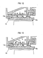
- FIG. 12 is a cross-sectional view showing a seventh embodiment of the structure of the present invention.
- vertical impingement cooling holes first impingement cooling holes 22
- first impingement cooling holes 22 are additionally provided to locally cool a location where the metal temperature increases.
- FIG. 13 is a cross-sectional view showing an eighth embodiment of the structure of the present invention.
- shroud members 10 each have a non-hole fin 18 which divides a cavity 2 into a plurality of sub-cavities.
- the non-hole fin 18 means a fin which does not have the second impingement cooling hole 12a.
- a test piece 5 which simulates a turbine shroud is produced.
- a metal surface temperature Tmg of the mainstream side of the test piece 5 is measured, and cooling efficiency ⁇ is calculated.
- FIG. 14B shows a structure (multiple-stage oblique impingement) of the present invention used in the test
- FIG. 14C shows a conventional example 1 (no pin, fin)
- FIG. 14D shows a conventional example 2 (with pins). Other conditions are the same for all structures.
- FIG. 15 shows test results.
- the horizontal axis represents the ratio (wc/wg) of a cooling air flow rate wc to a hot mainstream air flow rate wg, and the vertical axis represents the cooling efficiency ⁇ .
- the cooling efficiency of the present invention is high compared with the conventional examples 1 and 2.
- wc/wg in the present invention is about 0.6% while wc/wg in the conventional examples is about 1.3%.
- the amount of air required can be reduced to 1/2 or less with the cooling efficiency ⁇ being maintained.
- FIG. 16 is an illustrative diagram showing a relationship between a gap ⁇ h between a radial outward end of a hole fin 12 and an inner surface of a shroud cover 20, and a height h of the hole fin.
- the value ( ⁇ h/h) obtained by dividing the gap ⁇ h between the fin tip and the plate by the fin height h is set to range from 0 (no gap) to 0.2, and a calculation of a cooling air flow rate and a heat transfer analysis are performed.
- FIG. 17 shows the analysis results.
- the horizontal axis represents the axial length and the vertical axis represents the metal temperature of a gas passing surface (metal surface temperature on the mainstream side). Lines in the drawing represent results for ⁇ h/h ranging from 0 to 0.2.
- FIG. 18 is an illustrative diagram showing a relationship between the angle ⁇ of the second impingement cooling hole 12a and the height e of an impingement.
- FIG. 19 shows the test results.
- the horizontal axis represents the cooling air flow rate, and the vertical axis represents the average cooling efficiency.
- Solid circles and open circles in the graph represent the test results for 30° and 45°, respectively.
- FIGS. 20A, 20B, and 20C show the test results.
- the horizontal axis represents the cooling air flow rate and the vertical axis represents the average cooling efficiency.
- Solid circles and open circles in each graph represent the test results for the value of e/L being 0.13 and 0.26, respectively.
- the cooling efficiency when e/L is 0.13 is higher.
- the angle ⁇ preferably stands at or below about 45°.
- the value of e/L is preferably small, preferably 0.26 or less.
- the shroud cover 20 has the first impingement cooling hole 22 which allows cooling air 3 to be jetted in a cavity 2 formed between the shroud cover 20 and the shroud members 10, to cool the inner surface of the cavity by impingement
- the shroud members 10 each have the hole fin 12 which divides the cavity 2 into a plurality of sub-cavities
- the hole fin 12 has a second impingement cooling hole 12a which allows the cooling air 3 having flowed through the first impingement cooling hole 22 to be jetted obliquely toward the bottom surface of the adjacent sub-cavity.
Landscapes
- Engineering & Computer Science (AREA)
- Mechanical Engineering (AREA)
- General Engineering & Computer Science (AREA)
- Turbine Rotor Nozzle Sealing (AREA)
Claims (8)
- Prallgekühlte Struktur, die umfasst:eine Vielzahl von Deckband-Elementen (10), die in einer Umfangsrichtung angeordnet sind und ein ringförmiges Deckband bilden, das einen heißen Gasstrom (1) umschließt; sowieeinen Deckband-Verschluss (20), der an radialen Außenflächen der Deckband-Elemente (10) angebracht ist und einen Hohlraum (2) dazwischen bildet,wobei der Deckband-Verschluss (20) ein erstes Prallkühlungs-Loch (22) aufweist, das mit dem Hohlraum (2) in Verbindung steht und zulässt, dass Kühlluft (3) in einen Innenraum desselben eingeblasen wird, um eine Innenfläche (11) des Hohlraums (2) mittels Aufprall zu kühlen,die Deckband-Elemente (10) jeweils eine Lochrippe (12) aufweisen,die Lochrippe (12) den Hohlraum (2) in eine Vielzahl von Teil-Hohlräumen (2a, 2b, 2c) unterteilt,die Lochrippe (12) ein zweites Prallkühlungs-Loch (12a) aufweist, das zulässt, dass die Kühlluft (3), die durch das erste Prallkühlungs-Loch (22) geströmt ist, schräg auf eine Bodenfläche des daran angrenzenden Teil-Hohlraums (2b, 2c) zu geblasen wird,dadurch gekennzeichnet, dasssich die Lochrippe (12) von der Außenfläche (13), die die Bodenfläche des Hohlraums (2) bildet, in einer Richtung radial nach außen zu einer Innenfläche des Deckband-Verschlusses (20) erstreckt, und so den Hohlraum (2) in die Vielzahl von Teil-Hohlräumen (2a, 2b, 2c) unterteilt, die entlang des heißen Gasstroms (1) aneinandergrenzen.
- Prallgekühlte Struktur nach Anspruch 1, wobei die Deckband-Elemente (10) jeweils aufweisen:eine Innenfläche (11), die sich so an dem heißen Gasstrom (1) entlang erstreckt, dass sie dem heißen Gasstrom (1) direkt ausgesetzt ist; eine Außenfläche (13), die an einer Außenseite der Innenfläche (11) angeordnet ist und eine Bodenfläche des Hohlraums (2) bildet; einen stromauf liegenden Flansch (14), der sich von einer stromauf liegenden Seite des heißen Gasstroms (1) in einer radialen Richtung nach außen erstreckt und an einem Befestigungsabschnitt (33) befestigt ist, sowie einen stromab liegenden Flansch (15), der sich von einer stromab liegenden Seite des heißen Gasstroms (1) in einer radialen Richtung nach außen erstreckt und an dem Befestigungsabschnitt (33) befestigt ist,wobei der stromauf liegende Flansch (14) und der stromab liegende Flansch (15) dazu dienen, eine Kühlluft-Kammer (4) außerhalb des Deckband-Verschlusses (20) zu bilden.
- Prallgekühlte Struktur nach Anspruch 2, wobei der stromauf liegende Flansch (14) und/oder der stromab liegende Flansch (15) ein drittes Prallkühlungs-Loch (14a, 15a) aufweisen, das zulässt, dass die Kühlluft (3) aus dem Hohlraum (2) auf eine Außenfläche des Flansches (14, 15) zu geblasen wird.
- Prallgekühlte Struktur nach Anspruch 2, wobei die Deckband-Elemente (10) jeweils ein Filmkühlungs-Loch (16a, 16b) aufweisen, das zulässt, dass die Kühlluft (3) aus dem Hohlraum (2) auf die Innenfläche (11) des Deckband-Elementes (10) zu geblasen wird.
- Prallgekühlte Struktur nach Anspruch 1, die einen Turbulenzerzeuger (17), einen Vorsprung oder einen Zapfen an der Bodenfläche des Hohlraums (2) umfasst, wobei der Turbulenzerzeuger (17) Turbulenz erzeugt, und der Vorsprung oder der Zapfen eine Wärmeübertragungsfläche vergrößert.
- Prallgekühlte Struktur nach Anspruch 1, wobei die Deckband-Elemente (10) jeweils eine lochlose Rippe (18) aufweisen, die den Hohlraum (2) in eine Vielzahl von Teil-Hohlräumen unterteilt und einen Strömungsweg der Kühlluft (3) in zwei oder mehr Strömungswege unterteilt.
- Prallgekühlte Struktur nach Anspruch 2, wobei ein Spalt zwischen einem radial außenliegenden Ende der Loch-Rippe (12) und der Innenfläche des Deckband-Verschlusses (20) ausgebildet ist und eine Höhe Δh des Spalts 0,2 mal oder weniger so groß ist wie eine Höhe h der Loch-Rippe (12).
- Prallgekühlte Struktur nach Anspruch 2, wobei ein Winkel (θ) des zweiten Prallkühlungs-Lochs (12a) zu einer Bodenfläche eines Teilhohlraums 45° oder weniger beträgt und eine Aufprallhöhe e 0,26-mal oder weniger so groß ist wie eine Länge L des Teil-Hohlraums (2a, 2b, 2c) in einer Strömungsweg-Richtung.
Applications Claiming Priority (2)
| Application Number | Priority Date | Filing Date | Title |
|---|---|---|---|
| JP2006056084 | 2006-03-02 | ||
| PCT/JP2007/053486 WO2007099895A1 (ja) | 2006-03-02 | 2007-02-26 | インピンジメント冷却構造 |
Publications (3)
| Publication Number | Publication Date |
|---|---|
| EP1990507A1 EP1990507A1 (de) | 2008-11-12 |
| EP1990507A4 EP1990507A4 (de) | 2014-04-23 |
| EP1990507B1 true EP1990507B1 (de) | 2015-04-15 |
Family
ID=38459002
Family Applications (1)
| Application Number | Title | Priority Date | Filing Date |
|---|---|---|---|
| EP07714918.5A Ceased EP1990507B1 (de) | 2006-03-02 | 2007-02-26 | Prallkühlungsstruktur |
Country Status (5)
| Country | Link |
|---|---|
| US (1) | US8137056B2 (de) |
| EP (1) | EP1990507B1 (de) |
| JP (1) | JP4845957B2 (de) |
| CA (1) | CA2644099C (de) |
| WO (1) | WO2007099895A1 (de) |
Cited By (2)
| Publication number | Priority date | Publication date | Assignee | Title |
|---|---|---|---|---|
| US10370983B2 (en) | 2017-07-28 | 2019-08-06 | Rolls-Royce Corporation | Endwall cooling system |
| EP3246533B1 (de) * | 2016-05-18 | 2023-06-28 | Raytheon Technologies Corporation | Geformte kühlkanäle für aussendichtung für eine turbinenschaufel |
Families Citing this family (56)
| Publication number | Priority date | Publication date | Assignee | Title |
|---|---|---|---|---|
| US8439629B2 (en) * | 2007-03-01 | 2013-05-14 | United Technologies Corporation | Blade outer air seal |
| US8177492B2 (en) * | 2008-03-04 | 2012-05-15 | United Technologies Corporation | Passage obstruction for improved inlet coolant filling |
| CH699232A1 (de) * | 2008-07-22 | 2010-01-29 | Alstom Technology Ltd | Gasturbine. |
| EP2184445A1 (de) * | 2008-11-05 | 2010-05-12 | Siemens Aktiengesellschaft | Axial segmentierter Leitschaufelträger für einen Gasturbine |
| GB0904118D0 (en) | 2009-03-11 | 2009-04-22 | Rolls Royce Plc | An impingement cooling arrangement for a gas turbine engine |
| US9145779B2 (en) * | 2009-03-12 | 2015-09-29 | United Technologies Corporation | Cooling arrangement for a turbine engine component |
| EP2405103B1 (de) * | 2009-08-24 | 2016-05-04 | Mitsubishi Heavy Industries, Ltd. | Geteiltem ring mit kühlstruktur |
| JP2011208624A (ja) * | 2010-03-31 | 2011-10-20 | Hitachi Ltd | 高温部材の冷却構造 |
| FR2962484B1 (fr) * | 2010-07-08 | 2014-04-25 | Snecma | Secteur d'anneau de turbine de turbomachine equipe de cloison |
| US9458855B2 (en) | 2010-12-30 | 2016-10-04 | Rolls-Royce North American Technologies Inc. | Compressor tip clearance control and gas turbine engine |
| US8876458B2 (en) * | 2011-01-25 | 2014-11-04 | United Technologies Corporation | Blade outer air seal assembly and support |
| US20130028704A1 (en) * | 2011-07-26 | 2013-01-31 | Thibodeau Anne-Marie B | Blade outer air seal with passage joined cavities |
| US8826668B2 (en) * | 2011-08-02 | 2014-09-09 | Siemens Energy, Inc. | Two stage serial impingement cooling for isogrid structures |
| US9238970B2 (en) * | 2011-09-19 | 2016-01-19 | United Technologies Corporation | Blade outer air seal assembly leading edge core configuration |
| US20140130504A1 (en) * | 2012-11-12 | 2014-05-15 | General Electric Company | System for cooling a hot gas component for a combustor of a gas turbine |
| US9719362B2 (en) | 2013-04-24 | 2017-08-01 | Honeywell International Inc. | Turbine nozzles and methods of manufacturing the same |
| EP2835500A1 (de) | 2013-08-09 | 2015-02-11 | Siemens Aktiengesellschaft | Einsatzelement und Gasturbine |
| EP2860358A1 (de) | 2013-10-10 | 2015-04-15 | Alstom Technology Ltd | Anordnung zur Kühlung einer Komponente im Heißgaspfad einer Gasturbine |
| US9657642B2 (en) | 2014-03-27 | 2017-05-23 | Honeywell International Inc. | Turbine sections of gas turbine engines with dual use of cooling air |
| US20160047549A1 (en) * | 2014-08-15 | 2016-02-18 | Rolls-Royce Corporation | Ceramic matrix composite components with inserts |
| US10280785B2 (en) * | 2014-10-31 | 2019-05-07 | General Electric Company | Shroud assembly for a turbine engine |
| EP3023596B1 (de) * | 2014-11-20 | 2019-01-02 | United Technologies Corporation | Innengekühlte turbinenplattform |
| EP3034803A1 (de) | 2014-12-16 | 2016-06-22 | Rolls-Royce Corporation | Hängersystem für eine turbinenmotorkomponente |
| EP3048262A1 (de) * | 2015-01-20 | 2016-07-27 | Alstom Technology Ltd | Wand für einen Heißgaskanal in einer Gasturbine |
| US10221715B2 (en) | 2015-03-03 | 2019-03-05 | Rolls-Royce North American Technologies Inc. | Turbine shroud with axially separated pressure compartments |
| US9849510B2 (en) | 2015-04-16 | 2017-12-26 | General Electric Company | Article and method of forming an article |
| US9976441B2 (en) | 2015-05-29 | 2018-05-22 | General Electric Company | Article, component, and method of forming an article |
| US10641120B2 (en) * | 2015-07-24 | 2020-05-05 | Rolls-Royce Corporation | Seal segment for a gas turbine engine |
| US10739087B2 (en) | 2015-09-08 | 2020-08-11 | General Electric Company | Article, component, and method of forming an article |
| US10087776B2 (en) | 2015-09-08 | 2018-10-02 | General Electric Company | Article and method of forming an article |
| US10253986B2 (en) | 2015-09-08 | 2019-04-09 | General Electric Company | Article and method of forming an article |
| US20170198602A1 (en) * | 2016-01-11 | 2017-07-13 | General Electric Company | Gas turbine engine with a cooled nozzle segment |
| RU2706210C2 (ru) | 2016-01-25 | 2019-11-14 | Ансалдо Энерджиа Свитзерлэнд Аг | Тепловой экран статора для газовой турбины, газовая турбина с таким тепловым экраном статора и способ охлаждения теплового экрана статора |
| US10184343B2 (en) | 2016-02-05 | 2019-01-22 | General Electric Company | System and method for turbine nozzle cooling |
| US10344611B2 (en) | 2016-05-19 | 2019-07-09 | United Technologies Corporation | Cooled hot section components for a gas turbine engine |
| GB201612646D0 (en) * | 2016-07-21 | 2016-09-07 | Rolls Royce Plc | An air cooled component for a gas turbine engine |
| JP6821386B2 (ja) * | 2016-10-21 | 2021-01-27 | 三菱重工業株式会社 | 回転機械 |
| US10767490B2 (en) * | 2017-09-08 | 2020-09-08 | Raytheon Technologies Corporation | Hot section engine components having segment gap discharge holes |
| KR102000830B1 (ko) * | 2017-09-11 | 2019-07-16 | 두산중공업 주식회사 | 가스 터빈 블레이드 |
| US20190218925A1 (en) * | 2018-01-18 | 2019-07-18 | General Electric Company | Turbine engine shroud |
| US11268402B2 (en) * | 2018-04-11 | 2022-03-08 | Raytheon Technologies Corporation | Blade outer air seal cooling fin |
| EP3564484A1 (de) | 2018-05-04 | 2019-11-06 | Siemens Aktiengesellschaft | Bauteilwand eines heissgasbauteils |
| US10934876B2 (en) * | 2018-07-18 | 2021-03-02 | Raytheon Technologies Corporation | Blade outer air seal AFT hook retainer |
| US10989068B2 (en) | 2018-07-19 | 2021-04-27 | General Electric Company | Turbine shroud including plurality of cooling passages |
| US10837315B2 (en) * | 2018-10-25 | 2020-11-17 | General Electric Company | Turbine shroud including cooling passages in communication with collection plenums |
| US10830050B2 (en) * | 2019-01-31 | 2020-11-10 | General Electric Company | Unitary body turbine shrouds including structural breakdown and collapsible features |
| KR102178956B1 (ko) | 2019-02-26 | 2020-11-16 | 두산중공업 주식회사 | 터빈 베인 및 링세그먼트와 이를 포함하는 가스 터빈 |
| CN110145373B (zh) * | 2019-05-10 | 2022-04-15 | 沈阳航空航天大学 | 一种非均匀的横纵槽涡轮外环结构 |
| CN110332023B (zh) * | 2019-07-16 | 2021-12-28 | 中国航发沈阳发动机研究所 | 一种具有冷却功能的端面密封结构 |
| US11035248B1 (en) * | 2019-11-25 | 2021-06-15 | General Electric Company | Unitary body turbine shrouds including shot peen screens integrally formed therein and turbine systems thereof |
| JP6799702B1 (ja) * | 2020-03-19 | 2020-12-16 | 三菱パワー株式会社 | 静翼及びガスタービン |
| US11365645B2 (en) * | 2020-10-07 | 2022-06-21 | Pratt & Whitney Canada Corp. | Turbine shroud cooling |
| KR102502652B1 (ko) * | 2020-10-23 | 2023-02-21 | 두산에너빌리티 주식회사 | 물결 형태 유로를 구비한 배열 충돌제트 냉각구조 |
| CN113123833B (zh) * | 2021-03-26 | 2022-05-10 | 北京航空航天大学 | 一种分腔供气的涡轮外环块供气结构 |
| CN113638777B (zh) * | 2021-09-10 | 2023-09-15 | 中国航发湖南动力机械研究所 | 一种涡轮外环卡箍、涡轮外环的冷却结构、涡轮及发动机 |
| JP7764682B2 (ja) * | 2023-12-26 | 2025-11-06 | ドゥサン エナービリティー カンパニー リミテッド | エアフォイルおよびこれを含むガスタービン |
Family Cites Families (15)
| Publication number | Priority date | Publication date | Assignee | Title |
|---|---|---|---|---|
| CH584833A5 (de) * | 1975-05-16 | 1977-02-15 | Bbc Brown Boveri & Cie | |
| JPS51147805A (en) * | 1975-06-11 | 1976-12-18 | Norio Takahashi | Foundation continuously supporting rails |
| US4526226A (en) | 1981-08-31 | 1985-07-02 | General Electric Company | Multiple-impingement cooled structure |
| FR2724973B1 (fr) * | 1982-12-31 | 1996-12-13 | Snecma | Dispositif d'etancheite d'aubages mobiles de turbomachine avec controle actif des jeux en temps reel et methode de determination dudit dispositif |
| US4650394A (en) * | 1984-11-13 | 1987-03-17 | United Technologies Corporation | Coolable seal assembly for a gas turbine engine |
| US5048288A (en) * | 1988-12-20 | 1991-09-17 | United Technologies Corporation | Combined turbine stator cooling and turbine tip clearance control |
| KR100364183B1 (ko) * | 1994-10-31 | 2003-02-19 | 웨스팅하우스 일렉트릭 코포레이션 | 냉각된플랫폼을구비한가스터빈블레이드 |
| US5584651A (en) * | 1994-10-31 | 1996-12-17 | General Electric Company | Cooled shroud |
| JPH11200805A (ja) * | 1998-01-14 | 1999-07-27 | Toshiba Corp | 構造要素の冷却方法、冷却用流路付構造要素および冷却用流路付ガスタービン翼 |
| US6146091A (en) * | 1998-03-03 | 2000-11-14 | Mitsubishi Heavy Industries, Ltd. | Gas turbine cooling structure |
| JP3631898B2 (ja) * | 1998-03-03 | 2005-03-23 | 三菱重工業株式会社 | ガスタービンにおける分割環の冷却構造 |
| JPH11257003A (ja) * | 1998-03-06 | 1999-09-21 | Mitsubishi Heavy Ind Ltd | インピンジメント冷却装置 |
| EP1124039A1 (de) * | 2000-02-09 | 2001-08-16 | General Electric Company | Vorrichtung zur Prallkühlung des Deckbandes in einer Gasturbine |
| US6779597B2 (en) | 2002-01-16 | 2004-08-24 | General Electric Company | Multiple impingement cooled structure |
| US7033138B2 (en) * | 2002-09-06 | 2006-04-25 | Mitsubishi Heavy Industries, Ltd. | Ring segment of gas turbine |
-
2007
- 2007-02-26 EP EP07714918.5A patent/EP1990507B1/de not_active Ceased
- 2007-02-26 JP JP2008502758A patent/JP4845957B2/ja active Active
- 2007-02-26 WO PCT/JP2007/053486 patent/WO2007099895A1/ja not_active Ceased
- 2007-02-26 CA CA2644099A patent/CA2644099C/en not_active Expired - Fee Related
- 2007-02-26 US US12/281,369 patent/US8137056B2/en active Active
Cited By (2)
| Publication number | Priority date | Publication date | Assignee | Title |
|---|---|---|---|---|
| EP3246533B1 (de) * | 2016-05-18 | 2023-06-28 | Raytheon Technologies Corporation | Geformte kühlkanäle für aussendichtung für eine turbinenschaufel |
| US10370983B2 (en) | 2017-07-28 | 2019-08-06 | Rolls-Royce Corporation | Endwall cooling system |
Also Published As
| Publication number | Publication date |
|---|---|
| US20090035125A1 (en) | 2009-02-05 |
| CA2644099C (en) | 2013-12-31 |
| JP4845957B2 (ja) | 2011-12-28 |
| EP1990507A1 (de) | 2008-11-12 |
| EP1990507A4 (de) | 2014-04-23 |
| US8137056B2 (en) | 2012-03-20 |
| WO2007099895A1 (ja) | 2007-09-07 |
| CA2644099A1 (en) | 2007-09-07 |
| JPWO2007099895A1 (ja) | 2009-07-16 |
Similar Documents
| Publication | Publication Date | Title |
|---|---|---|
| EP1990507B1 (de) | Prallkühlungsstruktur | |
| CA2372984C (en) | Gas turbine segmental ring | |
| US8667682B2 (en) | Method of fabricating a nearwall nozzle impingement cooled component for an internal combustion engine | |
| JP6928995B2 (ja) | 翼のためのテーパした冷却チャネル | |
| EP2825748B1 (de) | Kühlkanal für ein gasturbinentriebwerk und gasturbinentriebwerk | |
| US6283708B1 (en) | Coolable vane or blade for a turbomachine | |
| US8246307B2 (en) | Blade for a rotor | |
| US9896942B2 (en) | Cooled turbine guide vane or blade for a turbomachine | |
| US6746209B2 (en) | Methods and apparatus for cooling gas turbine engine nozzle assemblies | |
| US10787911B2 (en) | Cooling configuration for a gas turbine engine airfoil | |
| JP2013508610A (ja) | 冷却流路を形成するテーパ状冷却構造体を組み込んだ翼 | |
| KR20150110367A (ko) | 냉각된 필릿을 갖는 터빈 베인 | |
| US9163518B2 (en) | Full coverage trailing edge microcircuit with alternating converging exits | |
| GB2301405A (en) | Gas turbine guide nozzle vane | |
| CN106468186A (zh) | 用于涡轮构件的热调节的制品和歧管 | |
| JP6906907B2 (ja) | 固定ブレード用冷却構造体 | |
| JP4234650B2 (ja) | 冷却式ガスタービンエンジン羽根 | |
| JP2001521599A (ja) | タービン翼、その用途ならびにタービン翼の冷却方法 | |
| US11261739B2 (en) | Airfoil with rib communication |
Legal Events
| Date | Code | Title | Description |
|---|---|---|---|
| PUAI | Public reference made under article 153(3) epc to a published international application that has entered the european phase |
Free format text: ORIGINAL CODE: 0009012 |
|
| 17P | Request for examination filed |
Effective date: 20080901 |
|
| AK | Designated contracting states |
Kind code of ref document: A1 Designated state(s): FR GB |
|
| DAX | Request for extension of the european patent (deleted) | ||
| RBV | Designated contracting states (corrected) |
Designated state(s): FR GB |
|
| A4 | Supplementary search report drawn up and despatched |
Effective date: 20140320 |
|
| RIC1 | Information provided on ipc code assigned before grant |
Ipc: F01D 25/24 20060101AFI20140314BHEP Ipc: F01D 11/08 20060101ALN20140314BHEP Ipc: F02C 7/18 20060101ALI20140314BHEP |
|
| 17Q | First examination report despatched |
Effective date: 20140916 |
|
| GRAP | Despatch of communication of intention to grant a patent |
Free format text: ORIGINAL CODE: EPIDOSNIGR1 |
|
| RIC1 | Information provided on ipc code assigned before grant |
Ipc: F01D 11/08 20060101ALN20141010BHEP Ipc: F02C 7/18 20060101ALI20141010BHEP Ipc: F01D 25/24 20060101AFI20141010BHEP |
|
| INTG | Intention to grant announced |
Effective date: 20141104 |
|
| GRAS | Grant fee paid |
Free format text: ORIGINAL CODE: EPIDOSNIGR3 |
|
| GRAA | (expected) grant |
Free format text: ORIGINAL CODE: 0009210 |
|
| AK | Designated contracting states |
Kind code of ref document: B1 Designated state(s): FR GB |
|
| REG | Reference to a national code |
Ref country code: GB Ref legal event code: FG4D |
|
| REG | Reference to a national code |
Ref country code: FR Ref legal event code: PLFP Year of fee payment: 10 |
|
| PLBE | No opposition filed within time limit |
Free format text: ORIGINAL CODE: 0009261 |
|
| STAA | Information on the status of an ep patent application or granted ep patent |
Free format text: STATUS: NO OPPOSITION FILED WITHIN TIME LIMIT |
|
| 26N | No opposition filed |
Effective date: 20160118 |
|
| REG | Reference to a national code |
Ref country code: FR Ref legal event code: PLFP Year of fee payment: 11 |
|
| REG | Reference to a national code |
Ref country code: FR Ref legal event code: PLFP Year of fee payment: 12 |
|
| PGFP | Annual fee paid to national office [announced via postgrant information from national office to epo] |
Ref country code: FR Payment date: 20210113 Year of fee payment: 15 |
|
| PGFP | Annual fee paid to national office [announced via postgrant information from national office to epo] |
Ref country code: GB Payment date: 20210217 Year of fee payment: 15 |
|
| GBPC | Gb: european patent ceased through non-payment of renewal fee |
Effective date: 20220226 |
|
| PG25 | Lapsed in a contracting state [announced via postgrant information from national office to epo] |
Ref country code: FR Free format text: LAPSE BECAUSE OF NON-PAYMENT OF DUE FEES Effective date: 20220228 |
|
| PG25 | Lapsed in a contracting state [announced via postgrant information from national office to epo] |
Ref country code: GB Free format text: LAPSE BECAUSE OF NON-PAYMENT OF DUE FEES Effective date: 20220226 |