EP1990525B1 - Système de moteur et procédé pour le réglage de la commande du rapport air-combustible dans un système de moteur - Google Patents
Système de moteur et procédé pour le réglage de la commande du rapport air-combustible dans un système de moteur Download PDFInfo
- Publication number
- EP1990525B1 EP1990525B1 EP20070107648 EP07107648A EP1990525B1 EP 1990525 B1 EP1990525 B1 EP 1990525B1 EP 20070107648 EP20070107648 EP 20070107648 EP 07107648 A EP07107648 A EP 07107648A EP 1990525 B1 EP1990525 B1 EP 1990525B1
- Authority
- EP
- European Patent Office
- Prior art keywords
- value
- values
- control
- parameter
- gas sensor
- Prior art date
- Legal status (The legal status is an assumption and is not a legal conclusion. Google has not performed a legal analysis and makes no representation as to the accuracy of the status listed.)
- Ceased
Links
Images



Classifications
-
- F—MECHANICAL ENGINEERING; LIGHTING; HEATING; WEAPONS; BLASTING
- F02—COMBUSTION ENGINES; HOT-GAS OR COMBUSTION-PRODUCT ENGINE PLANTS
- F02D—CONTROLLING COMBUSTION ENGINES
- F02D41/00—Electrical control of supply of combustible mixture or its constituents
- F02D41/02—Circuit arrangements for generating control signals
- F02D41/14—Introducing closed-loop corrections
- F02D41/1438—Introducing closed-loop corrections using means for determining characteristics of the combustion gases; Sensors therefor
-
- F—MECHANICAL ENGINEERING; LIGHTING; HEATING; WEAPONS; BLASTING
- F02—COMBUSTION ENGINES; HOT-GAS OR COMBUSTION-PRODUCT ENGINE PLANTS
- F02D—CONTROLLING COMBUSTION ENGINES
- F02D41/00—Electrical control of supply of combustible mixture or its constituents
- F02D41/22—Safety or indicating devices for abnormal conditions
- F02D41/222—Safety or indicating devices for abnormal conditions relating to the failure of sensors or parameter detection devices
-
- F—MECHANICAL ENGINEERING; LIGHTING; HEATING; WEAPONS; BLASTING
- F01—MACHINES OR ENGINES IN GENERAL; ENGINE PLANTS IN GENERAL; STEAM ENGINES
- F01N—GAS-FLOW SILENCERS OR EXHAUST APPARATUS FOR MACHINES OR ENGINES IN GENERAL; GAS-FLOW SILENCERS OR EXHAUST APPARATUS FOR INTERNAL-COMBUSTION ENGINES
- F01N11/00—Monitoring or diagnostic devices for exhaust-gas treatment apparatus
- F01N11/007—Monitoring or diagnostic devices for exhaust-gas treatment apparatus the diagnostic devices measuring oxygen or air concentration downstream of the exhaust apparatus
Definitions
- the present invention relates to an engine system and a method in an engine system comprising an internal combustion engine with at least one cylinder, and air control means and/or fuel injection means, the engine system further comprising an exhaust gas treatment device, an upstream gas sensor, located upstream of the exhaust gas treatment device, and a downstream gas sensor, located downstream of, or at least partly within, the exhaust gas treatment device.
- Modem vehicles are equipped with exhaust gas treatment devices, known as catalytic converters, that convert toxic gases such as hydrocarbons (HC), carbon monoxide (CO) and nitrogen oxides (NOx) into substances such as carbon dioxide (CO2) nitrogen (N2) and water (H2O).
- catalytic converters that convert toxic gases such as hydrocarbons (HC), carbon monoxide (CO) and nitrogen oxides (NOx) into substances such as carbon dioxide (CO2) nitrogen (N2) and water (H2O).
- a gas sensor known as a lambda sensor
- An engine control unit is adapted to determine, based on outputs from the lambda sensor, the oxygen content in the exhaust gases, which is indicative of the lambda value of the air/fuel mixture provided to the engine, which in turn is controlled based partly on the sensor outputs.
- sensors of the same type can present slightly different outputs in identical measurement conditions. An erroneous output from the lambda sensor will affect the sensor output and air/fuel mixture control loop negatively. As a result, the requested lambd
- US5224345 suggests adjusting the measured values from an upstream lambda sensor with integrated measurement values from a lambda sensor located downstream of the catalytic converter.
- the downstream lambda sensor measurement values fluctuate, specially if a so called binary sensor is used, also the integrated measurement values will fluctuate, and this will result in a less than optimal accuracy for the adjustment of the upstream lambda sensor measurement values.
- An object of the invention is to improve the control of the air/fuel ratio in an internal combustion engine.
- a further object of the invention is to decrease variations in emission control qualities between different individual engine systems.
- Determining the adjustment parameter value(s) after the end of the time period during which the control parameter values are determined means that the adjustment parameter value(s) can be determined very accurately, since it is based on information gathered for a certain period of time, thus eliminating miscalculations due to instantaneous fluctuations in the outputs from the downstream gas sensor.
- the less than optimal accuracy for the adjustment of the upstream lambda sensor measurement values provided by the known art continuous adjustment of these values with integrated measurement values from the downstream sensor, will be substantially improved.
- the improved accuracy for the adjustment of the upstream lambda sensor measurement values will improve the control of the air/fuel ratio in the engine, and will decrease variations in emission control qualities between different individual engine systems.
- the finite time period is at least 10 seconds. This will secure that a enough values of the control parameter are obtained for determining the adjustment parameter in order to allow an accurate adjustment of the exhaust control. More preferably, the finite time period is at least 60 seconds. This will provide a substantial amount of values of the control parameter for determining the adjustment parameter, providing a very accurate adjustment of the lambda control.
- control parameter values are determined at least partly based on outputs from the downstream gas sensor.
- the control parameter values can be based on such outputs, e.g. they could be the result of data processing of the outputs. Such processing could for example involve outputs from a further downstream sensor of the engine system.
- the control parameter values could be direct outputs from the downstream gas sensor.
- the method comprises storing at least some of the control parameter values, the at least one value of the adjustment parameter being determined at least partly based on at least some of the stored control parameter values.
- the at least one value of the adjustment parameter is determined as a mean value of at least some of the control parameter values.
- the adjustment parameter value(s) could be obtained by integrating the control parameter values.
- the method comprises
- the method comprises determining the at least one value of the adjustment parameter as a mean value of at least some of the values of the control parameter related to the downstream gas sensor, determining the at least one value of the comparison parameter as a mean value of at least some of the values of the control parameter related to the upstream gas sensor, and determining to not use the adjustment parameter value for adjusting the control of the air control means and/or the fuel injection means if the difference between these mean values is larger than a predetermined deviation threshold value.
- mean values of the control parameter values are used for determining whether to adapt the lambda control of the engine system, the system will not discard the downstream control parameter values due large differences between the control parameter values having relative short duration. Such short duration deviations are not necessarily indicative of a serious malfunction: rather they will be due to temporary parameter fluctuations normally occurring in an exhaust control system.
- Fig. 1 shows a schematic view of parts of a vehicle engine system 1 comprising an internal combustion engine.
- the engine comprises at least one cylinder 2 with a reciprocating piston 3. Communication between the cylinder 2 and an inlet duct 4 is controlled by at least one inlet valve 5, and communication between the cylinder 2 and an exhaust duct 6 is controlled by at least one exhaust valve 7.
- an exhaust gas treatment device 8 in this presentation referred to as a first exhaust gas treatment device 8 or a first catalytic converter 8 is provided.
- a second exhaust gas treatment device 82 here also referred to as a second catalytic converter, is provided.
- the engine system 1 also comprises an engine control unit (ECU) 9, which can be provided as one unit or more than one logically interconnected physical units.
- the ECU 9 is adapted to control air control means 10 comprising a throttle valve 10, and fuel injection means 11 in the inlet duct 4.
- the fuel injection means 11 comprises at least one fuel injector 11 in the inlet duct 4.
- the fuel injection can be controlled individually for each cylinder, by a fuel injector being provided at a separate portion of the inlet duct 4 communicating with the respective cylinder, (so called port fuel injection).
- a fuel injector can be provided in each cylinder 2, (so called direct fuel injection).
- one single fuel injector can be provided for more than one cylinder, or all cylinders, for example at an upstream portion of the inlet duct communicating with more than one cylinder, or all cylinders.
- the fuel injection means 11 communicate with fuel storage means in the form of a fuel tank 20, via a fuel pump 21.
- the ECU 9 is also adapted to receive output signals from a downstream gas sensor 12 located downstream of the first catalytic converter 8, and upstream of the second catalytic converter 82.
- the ECU 9 is further adapted to receive output signals from an upstream gas sensor 13 located in the exhaust duct 6 between the cylinder 2 and the first catalytic converter 8.
- the ECU 9 is adapted to determine, based on outputs from the downstream and upstream sensors 12, 13, the oxygen content in the exhaust gases upstream and downstream, respectively, of the first catalytic converter 8. As is known in the art, the oxygen content in the exhaust gases is indicative of the lambda value of the air/fuel mixture provided to the engine.
- the downstream gas sensor can alternatively be located so as to detect gas directly in the first catalytic converter 8. Thereby, preferably the downstream gas sensor is located downstream of an upstream end of the first catalytic converter 8. As a further alternative the downstream gas sensor can be located so as to detect gas directly in the second catalytic converter 82.
- the gas sensors 12, 13 are provided in the form of lambda or oxygen sensors.
- the downstream gas sensor 12 is a so called narrowband (binary) oxygen sensor, giving a highly non-linear relationship between the oxygen content of the exhaust gas and the output signal voltage.
- the upstream gas sensor 13 is a wideband (linear) sensor, giving a more linear relationship between the oxygen content and the output signal voltage.
- the ECU 9 is also adapted to receive output signals from an air flow sensor 14 located in the inlet duct 4.
- the air flow can be computed based on parameters such as the inlet manifold pressure, throttle position, engine speed, inlet temperature, and atmospheric pressure.
- ignition means 16 comprising a spark plug 16 are provided and controllable individually by the ECU 9.
- the invention is also applicable to internal combustion engines with non-spark ignition, such as diesel engines or HCCI (Homogenous Charge Combustion Ignition) engines.
- the ECU 9 continuously receives 301 outputs U12, in the form of voltage levels, from the downstream gas sensor 12.
- the outputs V12 the binary downstream gas sensor is exemplified in fig. 4a , which is given for the presentation of the invention according to this embodiment.
- the output values of a binary lambda sensor are in practice more erratically distributed than in fig. 4 .
- the engine system is adapted to provide a so called bang-bang control of the air/fuel mixture so as to successively alternate between a rich and a lean mixture.
- a rich mixture will result in a relative high voltage output U12 from the downstream gas sensor 12
- a lean mixture will result in a relative low voltage output U12 from the downstream gas sensor 12.
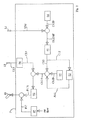
- the downstream sensor outputs U12 are compared 302 to a desired downstream sensor output U12D, and the differences U12Diff between the desired output U12D and the actual outputs U12 are continuously received by a downstream lambda control unit 91.
- the desired output U12D is determined by a desired output determination function 94 in dependence on the engine operational condition, and is based at least partly on the engine speed, engine load, air flow, etc. In this example, as depicted in fig. 4b , the difference U12Diff will alternate between a negative and a positive value.
- the downstream lambda control unit 91 is adapted to continuously determine 303 values of a downstream control parameter C12.
- the downstream control parameter values C12 will be adjusted so as to correspond to a richer air/fuel mixture, and vice versa.
- the resulting downstream control parameter values C12 are depicted in fig. 4c .
- the downstream control parameter values C12 are compared to a desired control parameter value C12D, preferably corresponding to a lambda value of 1. Based on this comparison, adjusted downstream control parameter values C12A are determined 304.
- the desired control parameter value C12D is determined by a desired control parameter value determination function 95, preferably based on the engine operating condition.
- the adjusted downstream control parameter values C12A are depicted in fig. 4d , and it is assumed that the desired control parameter value C12D is set so as to correspond to a lambda value of 1, and the adjusted downstream control parameter values C12A are determined as differences between the downstream control parameter values C12 and the desired control parameter value C12D.
- the ECU 9 continuously receives outputs U13, in the form of voltage levels, from the upstream gas sensor 13.
- the downstream sensor outputs U13 are continuously received by an upstream lambda control unit 96.
- the upstream lambda control unit 96 is adapted to continuously determine, based on the actual outputs U13, values of an upstream control parameter C13, in a manner corresponding to the determination of the downstream control parameter values C12 described above.
- the adjusted downstream control parameter values C12A, as well as the upstream control parameter values C13 are received by a lambda regulator 92.
- the adjusted downstream control parameter values C12A and the upstream control parameter values C13 correspond in this embodiment to desired lambda values, and actual lambda values, respectively.
- differences between the adjusted downstream control parameter values C12A and the upstream control parameter values C13 are determined, and based on these continuously determined differences the lambda regulator 92 is adapted to continuously send 305 fuel injection control adjustments FCA.
- the latter are used to adjust 306 fuel feed forward signals FC, which in turn are determined based on signals from the air flow sensor 14 ( fig. 1 ), by a fuel feed forward determination function 97.
- the air flow is adjusted by the throttle valve 10 at least partly based on requested torque parameter values Treq.
- the fuel injection means 11 is controlled by the fuel feed forward signals FC adjusted by the fuel injection control adjustments FCA.
- An adjustment parameter value A12 is determined 307 as follows:
- the downstream control parameter values C12 are continuously stored accessible to an adjustment unit 93.
- the adjustment unit 93 is adapted to determine a mean value of at least some of the stored downstream control parameter values C12 stored during a finite time period.
- the finite time period can be a predetermined time period, or based on a predetermined amount of gas flowing through the engine.
- the finite time period during which control parameter values C12 are stored is based on a predetermined number of switches of the control parameter values C12 from a lean to a rich mixture and vice versa.
- the finite time period is indicated as extending from the time t1 to the time t2, and corresponds to a time period during which the control parameter values C12 switches six times between a lean and a rich mixture.
- the accuracy of the adjustment parameter value A12 will increase with the number of switches included in the finite time period.
- the duration of the "rich periods" of the downstream gas sensor outputs U12 are longer than the duration of the "lean periods” thereof, periods during which the downstream control parameter values C12 correspond to a lean mixture are longer than the periods during which the downstream control parameter values C12 correspond to a rich mixture. Therefore the mean value of the downstream control parameter values C12 from the time t1 to the time t2 will correspond to a lean mixture. This is taken as an indication that the upstream gas sensor 13 provides values that are offset resulting in the engine control providing an air/fuel mixture that is too rich.
- the downstream control parameter values C12 are compared to the desired control parameter value C12D, and the adjustment parameter value A12.
- the adjusted downstream control parameter values C12A are determined 308 based on these comparisons. More particularly, the adjustment parameter value A12 is added to the difference between the downstream control parameter values C12 and the desired control parameter value C12D, and the resulting adjusted downstream control parameter values C12A are depicted in fig. 4e .
- the adjustment value A12 will provide 309 signals to provide a leaner control to compensate for the rich control caused by the off-set values from the upstream gas sensor 13.
- the adjustment value A12 is reviewed periodically, whereby the steps described above are repeated.
- Determining the adjustment parameter value A12 based on information gathered for a certain period of time, will eliminating miscalculations due to instantaneous fluctuations in the outputs from the downstream gas sensor.
- the adjustment parameter can be calculated by integrating the control parameter values stored during the finite time period.
- the adjustment parameter A12 can be determined as the integral of the control parameter values C12 from the time t1 to the time t2.
- the adjustment parameter A12 can be determined by calculating a mean value of the downstream gas sensor outputs U12 ( fig. 4a ) stored during the finite time period. More specifically, the downstream sensor outputs U12 can be continuously stored accessible to an adjustment unit 93, and a mean value of at least some of the stored downstream sensor outputs U12, stored during the finite time period, can be determined.
- a large difference between the downstream control parameter values C12 and the upstream control parameter values C13 may be an indication of a malfunction of the exhaust control system which is more serious than an off-set of the outputs of the upstream gas sensor 13.
- the adjustment unit 93 is adapted to determine a mean value of the stored downstream control parameter values C12 stored during a finite time period t1-t2 ( fig. 4c ).
- An upstream mean value determination function 961 is adapted to determine a value of a comparison parameter A13 as a mean value of the upstream control parameter values C13 received during the finite time period t1-t2.
- the adjustment unit 93 is adapted to compare the mean value of the downstream control parameter values C12 with the mean value of the upstream control parameter values C13. If the difference between these mean values is larger than a predetermined deviation threshold value, the mean value of the downstream control parameter values C12 will not be used to determine an adjustment parameter A12 for the lambda control.
- the deviation threshold value can be determined based at least partly on the engine speed and engine load.
- the downstream control parameter values C12 may still be used for adaptation of the lambda control.
- mean values of the control parameter values C12, C13 are used for determining whether to adapt the lambda control as described above, the system will not discard the downstream control parameter values C12 due large differences between the control parameter values C12, C13 having short durations Dt. Such short duration deviations are not necessarily indicative of a serious malfunction; rather they will be due to temporary parameter fluctuations normally occurring in an exhaust control system.
Landscapes
- Engineering & Computer Science (AREA)
- Chemical & Material Sciences (AREA)
- Combustion & Propulsion (AREA)
- Mechanical Engineering (AREA)
- General Engineering & Computer Science (AREA)
- Electrical Control Of Air Or Fuel Supplied To Internal-Combustion Engine (AREA)
Claims (10)
- Procédé dans un système de moteur (1) comprenant un moteur à combustion interne avec au moins un cylindre (2) et des moyens de commande de l'air (10) et/ou des moyens d'injection de carburant (11), le système de moteur comprenant en outre un dispositif de traitement (8) des gaz d'échappement, un capteur de gaz amont (13), situé en amont du dispositif de traitement (8) des gaz d'échappement, et un capteur de gaz aval (12), situé en aval du dispositif de traitement (8) des gaz d'échappement, ou au moins partiellement à l'intérieur de celui-ci, le procédé comprenant :- la détermination (301, 302, 303), au cours d'une période déterminée (t1-t2), d'une pluralité de valeurs d'un paramètre de commande (U12, U12Diff, C12) associées au détecteur de gaz aval (12),- la détermination (307), après la fin de la période déterminée (t1-t2), d'au moins une valeur d'un paramètre de réglage (A12) au moins partiellement basée sur au moins certaines des valeurs de paramètre de commande, et- le réglage (309) de la commande des moyens de commande de l'air (10) et/ou des moyens d'injection de carburant (11) au moins partiellement basé sur au moins une de la au moins une valeur de paramètre de réglage (A12), caractérisé en ce que la au moins une valeur du paramètre de réglage (A12) est déterminée (307) en tant que valeur moyenne d'au moins certaines des valeurs du paramètre de commande (U12, U12Diff, C12) et en ce que le procédé comprend en outre- la détermination, au cours de la période déterminée (t1-t2), d'une pluralité de valeurs d'un paramètre de commande (U13, C13) associées au capteur de gaz amont (13),- la détermination, après la fin de la période déterminée (t1-t2), d'au moins une valeur d'un paramètre de comparaison (A13) basée au moins partiellement sur au moins certaines des valeurs du paramètre de commande (U13, C13) associées au capteur de gaz amont (13),- la comparaison de la au moins une valeur du paramètre de comparaison (A13) avec la valeur du paramètre de réglage (A12), et- la détermination, basée au moins partiellement sur la comparaison entre la valeur du paramètre de comparaison (A13) et la valeur du paramètre de réglage (A12), s'il faut utiliser la valeur du paramètre de réglage (A12) pour régler (309) la commande des moyens de commande de l'air (10) et/ou des moyens d'injection de carburant (11).
- Procédé selon la revendication 1, dans lequel la période déterminée est d'au moins 10 secondes, de préférence d'au moins 60 secondes.
- Procédé selon l'une quelconque des revendications précédentes, dans lequel au moins certaines des valeurs du paramètre de commande (C12) sont déterminées (303) en se basant au moins partiellement sur les sorties (U12) du capteur de gaz aval (12).
- Procédé selon l'une quelconque des revendications précédentes, comprenant la mémorisation d'au moins certaines des valeurs du paramètre de commande (U12, U12Diff, C12), la au moins une valeur du paramètre de réglage (A12) étant déterminée (307) en se basant au moins partiellement sur au moins certaines des valeurs mémorisées du paramètre de commande (U12, U12Diff, C12).
- Procédé selon l'une quelconque des revendications 1 à 4, comprenant la détermination (307) de la au moins une valeur du paramètre de réglage (A12) en tant que valeur moyenne d'au moins certaines des valeurs du paramètre de commande (U12, U12Diff, C12) associées au capteur de gaz aval (12), la détermination de la au moins une valeur du paramètre de comparaison (A13) en tant que valeur moyenne d'au moins certaines des valeurs du paramètre de commande (U13, C13) associées au capteur de gaz amont (13) et la détermination du fait de ne pas utiliser la valeur du paramètre de réglage (A12) pour régler (309) la commande des moyens de commande de l'air (10) et/ou des moyens d'injection de carburant (11) si la différence entre ces valeurs moyennes (A12, A13) est plus grande qu'une la valeur seuil d'écart prédéterminée.
- Système de moteur comprenant un moteur à combustion interne avec au moins un cylindre (2) et des moyens de commande de l'air (10) et/ou des moyens d'injection de carburant (11), le système de moteur comprenant en outre un dispositif de traitement (8) des gaz d'échappement, un capteur de gaz amont (13) situé en amont du dispositif de traitement (8) des gaz d'échappement, un capteur de gaz aval (12) situé en aval du dispositif de traitement (8) des gaz d'échappement, ou au moins partiellement à l'intérieur de celui-ci, et un calculateur moteur (9), le calculateur moteur (9) étant adapté- pour déterminer (301, 302, 303), au cours d'une période déterminée (t1-t2), une pluralité de valeurs d'un paramètre de commande (U12, U12Diff, C12) associées au détecteur de gaz aval (12),- pour déterminer (307), après la fin de la période déterminée (t1-t2), au moins une valeur d'un paramètre de réglage (A12) au moins partiellement basée sur au moins certaines des valeurs de paramètre de commande,
et- pour régler (309) la commande des moyens de commande de l'air (10) et/ou des moyens d'injection de carburant (11) en se basant au moins partiellement sur au moins une de la au moins une valeur de paramètre du réglage (A12), caractérisé en ce que le calculateur moteur (9) est adapté pour déterminer (307) la au moins une valeur du paramètre de réglage (A12) en tant que valeur moyenne d'au moins certaines des valeurs du paramètre de commande (U12, U12Diff, C12) et en ce que le calculateur moteur (9) est adapté- pour déterminer, au cours de la période déterminée (t1-t2), une pluralité de valeurs d'un paramètre de commande (U13, C13) associées au capteur de gaz amont (13),- pour déterminer, après la fin de la période déterminée (t1-t2), au moins une valeur d'un paramètre de comparaison (A13) basée au moins partiellement sur au moins certaines des valeurs du paramètre de commande (U13, C13) associées au capteur de gaz amont (13),- pour comparer la au moins une valeur du paramètre de comparaison (A13) avec la valeur du paramètre de réglage (A12), et- pour déterminer, en se basant au moins partiellement sur la comparaison entre la valeur du paramètre de comparaison (A13) et la valeur du paramètre de réglage (A12), s'il faut utiliser la valeur du paramètre de réglage (A12) pour régler (309) la commande des moyens de commande de l'air (10) et/ou des moyens d'injection de carburant (11). - Système de moteur selon la revendication 6, dans lequel la période déterminée est d'au moins 10 secondes, de préférence d'au moins 60 secondes.
- Système de moteur selon l'une quelconque des revendications 6 et 7, dans lequel le calculateur moteur (9) est adapté pour déterminer (303) au moins certaines des valeurs du paramètre de commande (C12) basées au moins partiellement sur les sorties (U12) du capteur de gaz aval (12).
- Système de moteur selon l'une quelconque des revendications 6 à 8, dans lequel le calculateur moteur (9) est adapté pour mémoriser au moins certaines des valeurs du paramètre de commande (U12, U12Diff, C12) et pour déterminer (307) la au moins une valeur du paramètre de réglage (A12) basée au moins partiellement sur au moins certaines des valeurs mémorisées du paramètre de commande (U12, U12Diff, C12).
- Système de moteur selon l'une quelconque des revendications 6 à 9, dans lequel le calculateur moteur (9) est adapté pour déterminer (307) la au moins une valeur du paramètre de réglage (A12) en tant que valeur moyenne d'au moins certaines des valeurs du paramètre de commande (U12, U12Diff, C12) associées au capteur de gaz aval (12), pour déterminer la au moins une valeur du paramètre de comparaison (A13) en tant que valeur moyenne d'au moins certaines des valeurs du paramètre de commande (U13, C13) associées au capteur de gaz amont (13) et pour déterminer le fait de ne pas utiliser la valeur du paramètre de réglage (A12) pour régler (309) la commande des moyens de commande de l'air (10) et/ou des moyens d'injection de carburant (11) si la différence entre ces valeurs moyennes (A12, A13) est plus grande qu'une valeur seuil d'écart prédéterminée.
Priority Applications (1)
| Application Number | Priority Date | Filing Date | Title |
|---|---|---|---|
| EP20070107648 EP1990525B1 (fr) | 2007-05-07 | 2007-05-07 | Système de moteur et procédé pour le réglage de la commande du rapport air-combustible dans un système de moteur |
Applications Claiming Priority (1)
| Application Number | Priority Date | Filing Date | Title |
|---|---|---|---|
| EP20070107648 EP1990525B1 (fr) | 2007-05-07 | 2007-05-07 | Système de moteur et procédé pour le réglage de la commande du rapport air-combustible dans un système de moteur |
Publications (2)
| Publication Number | Publication Date |
|---|---|
| EP1990525A1 EP1990525A1 (fr) | 2008-11-12 |
| EP1990525B1 true EP1990525B1 (fr) | 2013-07-10 |
Family
ID=38430572
Family Applications (1)
| Application Number | Title | Priority Date | Filing Date |
|---|---|---|---|
| EP20070107648 Ceased EP1990525B1 (fr) | 2007-05-07 | 2007-05-07 | Système de moteur et procédé pour le réglage de la commande du rapport air-combustible dans un système de moteur |
Country Status (1)
| Country | Link |
|---|---|
| EP (1) | EP1990525B1 (fr) |
Family Cites Families (4)
| Publication number | Priority date | Publication date | Assignee | Title |
|---|---|---|---|---|
| DE3827978A1 (de) * | 1987-11-10 | 1989-05-18 | Bosch Gmbh Robert | Verfahren und vorrichtung fuer stetige lambdaregelung |
| WO1990005240A1 (fr) | 1988-11-09 | 1990-05-17 | Robert Bosch Gmbh | Procede et dispositif pour le reglage de la valeur de lambda |
| DE4125154C2 (de) * | 1991-07-30 | 2001-02-22 | Bosch Gmbh Robert | Verfahren und Einrichtung zur Lambdasonden-Überwachung bei einer Brennkraftmaschine |
| JP3372723B2 (ja) * | 1995-08-01 | 2003-02-04 | 本田技研工業株式会社 | 内燃機関の空燃比制御装置 |
-
2007
- 2007-05-07 EP EP20070107648 patent/EP1990525B1/fr not_active Ceased
Also Published As
| Publication number | Publication date |
|---|---|
| EP1990525A1 (fr) | 2008-11-12 |
Similar Documents
| Publication | Publication Date | Title |
|---|---|---|
| US8805609B2 (en) | Apparatus and method for detecting abnormal air-fuel ratio variation | |
| US8548718B2 (en) | Air/fuel ratio variation abnormality detection apparatus, and abnormality detection method | |
| US5533332A (en) | Method and apparatus for self diagnosis of an internal combustion engine | |
| US9043121B2 (en) | Air-fuel ratio variation abnormality detecting device and air-fuel ratio variation abnormality detecting method | |
| US5983714A (en) | System for detecting failure of fuel pressure sensor | |
| US6155242A (en) | Air/fuel ratio control system and method | |
| US8024105B2 (en) | Apparatus and method for detecting abnormal air-fuel ratio variation among cylinders of multi-cylinder internal combustion engine | |
| US5568725A (en) | Apparatus and method for controlling the air-fuel ratio of an internal combustion engine | |
| EP1705359A1 (fr) | Methode de correction précursive d'un moteur à combustion multicylindre et système de correction précursive correspondant de contrôle de l'injection | |
| US8249794B2 (en) | Inter-cylinder air-fuel ratio imbalance judgment device for multi-cylinder internal combustion engine | |
| US20130006505A1 (en) | Diagnostic apparatus for internal combustion engine | |
| US20130197786A1 (en) | Control apparatus and control method for multi-cylinder internal combustion engine | |
| JP4697201B2 (ja) | 内燃機関の異常検出装置 | |
| US8649956B2 (en) | Apparatus for acquiring responsibility of oxygen concentration sensor | |
| EP0597232A2 (fr) | (Dispositif) et méthode de commande pour moteur à combustion interne et à combustion pauvre | |
| US20120303248A1 (en) | Abnormality detection apparatus and abnormality detection method for multi-cylinder internal combustion engine | |
| US5390489A (en) | Air-fuel ratio control system for internal combustion engine | |
| JP2012092803A (ja) | 多気筒内燃機関の気筒間空燃比ばらつき異常検出装置 | |
| US8725389B2 (en) | Control device for multi-cylinder internal combustion engine | |
| US6684869B2 (en) | System and method for detecting an air leak in an engine | |
| US20060235604A1 (en) | Method of feedforward controlling a multi-cylinder internal combustion engine and associated feedforward fuel injection control system | |
| US9664096B2 (en) | Control apparatus for internal combustion engine | |
| US10443520B2 (en) | Control apparatus for internal combustion engine | |
| US7568476B2 (en) | Air-fuel ratio control system for internal combustion engine | |
| EP1990525B1 (fr) | Système de moteur et procédé pour le réglage de la commande du rapport air-combustible dans un système de moteur |
Legal Events
| Date | Code | Title | Description |
|---|---|---|---|
| PUAI | Public reference made under article 153(3) epc to a published international application that has entered the european phase |
Free format text: ORIGINAL CODE: 0009012 |
|
| AK | Designated contracting states |
Kind code of ref document: A1 Designated state(s): AT BE BG CH CY CZ DE DK EE ES FI FR GB GR HU IE IS IT LI LT LU LV MC MT NL PL PT RO SE SI SK TR |
|
| AX | Request for extension of the european patent |
Extension state: AL BA HR MK RS |
|
| 17P | Request for examination filed |
Effective date: 20090511 |
|
| AKX | Designation fees paid |
Designated state(s): DE GB SE |
|
| 17Q | First examination report despatched |
Effective date: 20100226 |
|
| RAP1 | Party data changed (applicant data changed or rights of an application transferred) |
Owner name: VOLVO CAR CORPORATION |
|
| GRAP | Despatch of communication of intention to grant a patent |
Free format text: ORIGINAL CODE: EPIDOSNIGR1 |
|
| GRAS | Grant fee paid |
Free format text: ORIGINAL CODE: EPIDOSNIGR3 |
|
| GRAA | (expected) grant |
Free format text: ORIGINAL CODE: 0009210 |
|
| AK | Designated contracting states |
Kind code of ref document: B1 Designated state(s): DE GB SE |
|
| REG | Reference to a national code |
Ref country code: GB Ref legal event code: FG4D |
|
| REG | Reference to a national code |
Ref country code: DE Ref legal event code: R096 Ref document number: 602007031517 Country of ref document: DE Effective date: 20130905 |
|
| REG | Reference to a national code |
Ref country code: SE Ref legal event code: TRGR |
|
| PLBE | No opposition filed within time limit |
Free format text: ORIGINAL CODE: 0009261 |
|
| STAA | Information on the status of an ep patent application or granted ep patent |
Free format text: STATUS: NO OPPOSITION FILED WITHIN TIME LIMIT |
|
| 26N | No opposition filed |
Effective date: 20140411 |
|
| REG | Reference to a national code |
Ref country code: DE Ref legal event code: R097 Ref document number: 602007031517 Country of ref document: DE Effective date: 20140411 |
|
| PGFP | Annual fee paid to national office [announced via postgrant information from national office to epo] |
Ref country code: SE Payment date: 20190515 Year of fee payment: 13 |
|
| PGFP | Annual fee paid to national office [announced via postgrant information from national office to epo] |
Ref country code: GB Payment date: 20190508 Year of fee payment: 13 |
|
| PG25 | Lapsed in a contracting state [announced via postgrant information from national office to epo] |
Ref country code: SE Free format text: LAPSE BECAUSE OF NON-PAYMENT OF DUE FEES Effective date: 20200508 |
|
| GBPC | Gb: european patent ceased through non-payment of renewal fee |
Effective date: 20200507 |
|
| PG25 | Lapsed in a contracting state [announced via postgrant information from national office to epo] |
Ref country code: GB Free format text: LAPSE BECAUSE OF NON-PAYMENT OF DUE FEES Effective date: 20200507 |
|
| PGFP | Annual fee paid to national office [announced via postgrant information from national office to epo] |
Ref country code: DE Payment date: 20230419 Year of fee payment: 17 |
|
| REG | Reference to a national code |
Ref country code: DE Ref legal event code: R119 Ref document number: 602007031517 Country of ref document: DE |
|
| PG25 | Lapsed in a contracting state [announced via postgrant information from national office to epo] |
Ref country code: DE Free format text: LAPSE BECAUSE OF NON-PAYMENT OF DUE FEES Effective date: 20241203 |