EP1990565B1 - Bague d'étanchéité et dispositif de joint comprenant la bague d'étanchéité - Google Patents
Bague d'étanchéité et dispositif de joint comprenant la bague d'étanchéité Download PDFInfo
- Publication number
- EP1990565B1 EP1990565B1 EP20070009010 EP07009010A EP1990565B1 EP 1990565 B1 EP1990565 B1 EP 1990565B1 EP 20070009010 EP20070009010 EP 20070009010 EP 07009010 A EP07009010 A EP 07009010A EP 1990565 B1 EP1990565 B1 EP 1990565B1
- Authority
- EP
- European Patent Office
- Prior art keywords
- spring
- sealing ring
- sealing
- sealed
- sealing lip
- Prior art date
- Legal status (The legal status is an assumption and is not a legal conclusion. Google has not performed a legal analysis and makes no representation as to the accuracy of the status listed.)
- Active
Links
Images


Classifications
-
- F—MECHANICAL ENGINEERING; LIGHTING; HEATING; WEAPONS; BLASTING
- F16—ENGINEERING ELEMENTS AND UNITS; GENERAL MEASURES FOR PRODUCING AND MAINTAINING EFFECTIVE FUNCTIONING OF MACHINES OR INSTALLATIONS; THERMAL INSULATION IN GENERAL
- F16J—PISTONS; CYLINDERS; SEALINGS
- F16J15/00—Sealings
- F16J15/16—Sealings between relatively-moving surfaces
- F16J15/32—Sealings between relatively-moving surfaces with elastic sealings, e.g. O-rings
- F16J15/3204—Sealings between relatively-moving surfaces with elastic sealings, e.g. O-rings with at least one lip
- F16J15/3208—Sealings between relatively-moving surfaces with elastic sealings, e.g. O-rings with at least one lip provided with tension elements, e.g. elastic rings
- F16J15/3212—Sealings between relatively-moving surfaces with elastic sealings, e.g. O-rings with at least one lip provided with tension elements, e.g. elastic rings with metal springs
-
- F—MECHANICAL ENGINEERING; LIGHTING; HEATING; WEAPONS; BLASTING
- F16—ENGINEERING ELEMENTS AND UNITS; GENERAL MEASURES FOR PRODUCING AND MAINTAINING EFFECTIVE FUNCTIONING OF MACHINES OR INSTALLATIONS; THERMAL INSULATION IN GENERAL
- F16F—SPRINGS; SHOCK-ABSORBERS; MEANS FOR DAMPING VIBRATION
- F16F1/00—Springs
- F16F1/02—Springs made of steel or other material having low internal friction; Wound, torsion, leaf, cup, ring or the like springs, the material of the spring not being relevant
- F16F1/04—Wound springs
- F16F1/12—Attachments or mountings
Definitions
- the invention relates to a sealing ring comprising at least one dynamically stressed sealing lip which can be applied under elastic prestressing sealing to a sealed surface of a machine element to be sealed, wherein the sealing lip is radially outer peripheral side enclosed by an annular spring, wherein the spring has the shape of a helical compression spring, with Windings, which are associated with each other in the circumferential direction at a distance adjacent.
- Sealing rings are well known.
- the previously known sealing rings are formed for example as radial shaft seals, arranged in a relatively immovable housings stationary and dense rotating waves.
- the necessary for the sealing function of a radial shaft seal contact pressure of the sealing lip to the surface to be sealed is achieved in these cases by the radial expansion of the elastic sealing lip, which usually consists of an elastomeric material, and also by a tension spring which surrounds the outer edge of the sealing lip.
- the elastic sealing lip which usually consists of an elastomeric material
- a tension spring which surrounds the outer edge of the sealing lip.
- tension springs can be used with increased rigidity, the contact pressure of the spring by the winding ratio w (mean coil diameter of the spring to wire diameter) limits are set. Even with maximum utilization of this ratio, a lifting of the sealing lip at speeds greater than 5000 min -1 can no longer be prevented.
- seals which have at least one statically stressed sealing bead and are mounted with this stationary on the axis.
- the dynamically stressed sealing lip points radially outward and seals the inner peripheral side wall of a rotating housing.
- the necessary contact pressure of the sealing lip to the housing is achieved by a compression spring, wherein such a seal arrangement has an undesirably high friction between the sealing lip and housing due to the compression of the sealing lip and the compression spring.
- a helical spring having a number of interconnected connections which are spaced apart from one another. Each turn is at a predetermined acute angle to the center line of the Coil spring, so that the coil spring of its deflection in a loading direction, which extends approximately perpendicular to the center line of the coil spring, in a predetermined range opposes a substantially constant force.
- the ends of the spring may be connected to a ring. The object to be achieved is seen in compensating for changing conditions, such as dimensional changes due to wear, temperature and pressure change, with constant force of the coil spring.
- the helical spring can be used in a sealing ring made of elastomeric material, wherein a distance between the windings of about 0.2 mm is described for the illustrated embodiment.
- the sealing ring seals rotating or oscillating waves and is arranged in a stationary housing.
- a sealing ring is known, with a dynamically stressed sealing lip, which can be applied under elastic prestressing sealing to a sealed surface of an axis to be sealed.
- the sealing lip is held by a tension spring on the surface to be sealed, wherein the object of the prior art sealing ring is seen therein to keep the sealing lip on the surface to be sealed at high speeds of the sealing ring.
- the tension spring be held by holding devices on the surface to be sealed. These holding devices may be formed, for example, in that the tension spring is largely embedded in the elastomeric material of the sealing lip.
- the tension spring is in Fig. 3 schematically illustrated, which is described in the figure description that the tension spring is enclosed by a rubber body.
- the tension spring has a coil diameter of 4 mm, the wire diameter being 0.9 mm. According to another embodiment, the Winding diameter 3 mm, while the wire diameter is 0.45 mm. The winding ratio is therefore in one case about 4.5 in the other case 6.7.
- sealing ring which has a spring-loaded sealing lip.
- the previously known sealing ring is designed as a radial shaft seal, for sealing a rotating shaft, wherein the friction between the sealing lip and the machine element to be sealed is to be reduced to a minimum. Under dynamic conditions, the static sealing lip should be lifted off the surface to be sealed.
- the invention has the object of providing a simple standard sealing ring of the type mentioned in such a way that even at speeds of the sealing ring> 5000 min -1 secure sealing of the dynamically stressed sealing lip on the surface to be sealed is given to be sealed axis, that is, a lifting of the sealing lip of the surface to be sealed and / or jumping off the tension spring of the sealing lip under the conditions mentioned is avoided.
- a sealing ring in which the spring to compensate for operational centrifugal forces has adjacent turns having a pitch of 1.5 mm to 2.3 mm, wherein adjacent turns neither in the manufacturing condition nor during the Touch as directed.
- a spring has, based on conventional springs, in which adjacent turns in the condition of the condition of the sealing ring (unloaded state) abut each other at least on the inner circumference side, the advantage that adjacent turns of the spring of the sealing ring according to the invention by the same circumference by its configuration on the inner peripheral side are always arranged with a circumferential distance from each other and that such a spring has a much lower mass. Since the centrifugal force acting on the spring is proportional to the mass of the spring and the number of revolutions squared, a spring in which adjacent turns are always arranged circumferentially adjacent to each other can have up to 80% less mass.
- the spring has the shape of a helical compression spring.
- the adjacent turns of the annular spring have a pitch of at least 1.5 mm.
- the spring characteristic can under Others also be influenced by the slope of the spring winding. The greater the pitch of the spring coil, the higher the stiffness of the spring.
- sealing rings according to the invention can also be used arrive when in rotating cases with speeds of z. B. 12000 min -1 and more are operated. Even at these high speeds, a reliable contact pressure of the sealing lip is achieved on the surface to be sealed by the special design of the spring.
- the two front ends of the production-related straight spring may be formed together as a spring lock. It is advantageous that the ends of the spring can be easily and inexpensively connect to each other, for example, the fact that the spring for connecting the two ends together is first turned on something that the two ends then connected together and connect the spin automatically reversed becomes. Subsequently, the spring is annular.
- the spring may have a winding ratio w ⁇ 4.
- the winding ratio w describes the ratio of the mean winding diameter of the spring to the wire diameter. Winding ratios w ⁇ 4.5 are conventional
- the sealing lip is preferably made of an elastomeric material. Sealing rings with sealing lips made of elastomeric materials can be particularly easily adapted to the particular circumstances of the application and are simple and inexpensive to produce.
- the invention also relates to a sealing arrangement, comprising a sealing ring as described above, wherein the sealing ring with its sealing lip sealingly seals a sealed surface of an axis to be sealed under radial prestress, wherein the sealing ring is stationary in a housing and rotatably disposed together with the housing about the axis ,
- a seal arrangement is used, for example, for sealing hubs in cars or trucks or for sealing centrifuges or retarders.
- Such a seal assembly is tight even at speeds in the range of 12000 min -1 , since the sealing lip does not stand out from the surface to be sealed by the special, previously described spring even at such high speeds; In addition, the high stiffness of the spring, the risk that it jumps, reduced to a minimum.
- the invention relates to the use of a helical compression spring as a spring of a sealing ring and a sealing arrangement, each as described above.
- a helical compression spring as a spring of a sealing ring and a sealing arrangement, each as described above.
- Sealing rings with sealing lips made of elastomeric materials are also used when they rotate at speeds of more than 5000 min -1 around an axis. Expensive special designs for sealing under these operating conditions are therefore not required. Sealing rings, which have excellent performance characteristics for a long service life for this particular application, are easy and inexpensive to produce.
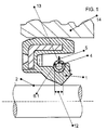
- FIG. 1 an embodiment of the seal assembly according to the invention is shown.
- the sealing arrangement comprises the sealing ring, which is designed as a radial shaft seal and has a dynamically stressed sealing lip 1.
- the dynamically stressed sealing lip 1 surrounds the sealed surface 2 of the sealed axis 3 under elastic prestressing sealing, wherein the sealing lip 1 is radially outer peripheral side of the annular spring 4 is enclosed.
- the sealing ring is pressed in place in the housing 14 and runs together with the housing 14 about the axis 3.
- the spring 4 is corresponding to the Figures 2 and 3 educated.
- FIG. 2 and 3 is the spring 4 off FIG. 1 shown as a single part.
- the spring 4 has turns 6.1, 6.2,. FIG. 2 ) / peripheral ( FIG. 3 ) Distance 7 are assigned adjacent.
- the spring 4 has the shape of a helical compression spring, wherein the adjacent turns 6.1, 6.2; 6.2, 6.3; ... have a pitch 8 of 1.5 mm in the exemplary embodiment shown here. Neither in the manufacturing condition ( FIG. 2 ), during the intended use ( FIG. 1 and FIG. 3 ) adjacent turns 6.1, 6.2; 6.2, 6.3; ....
- the two ends 9, 10 of the spring 4 are formed such that they, as in FIG. 3 shown, form a spring lock 11.
- the spring 4 has in the embodiment shown here, a winding ratio w of 3.8.
- a stiffness of the spring is achieved, which is proportional to the slope, wherein the spring has a lower mass, the greater the slope.
- FIGS. 4 and 5 conventional tension springs are shown as they are used in the prior art.
- the adjacent turns 6.1, 6.2, 6.3, ... are directly adjacent to each other and the number of turns 6.1, 6.2, 6.3, ... is comparatively large, whereby a high mass is conditional.
Landscapes
- Engineering & Computer Science (AREA)
- General Engineering & Computer Science (AREA)
- Mechanical Engineering (AREA)
- Sealing With Elastic Sealing Lips (AREA)
- Sealing Devices (AREA)
Claims (6)
- Bague d'étanchéité, comprenant au moins une lèvre d'étanchéité (1) à contrainte dynamique, qui peut être appliquée par précontrainte élastique de manière hermétique contre une surface (2) à étanchéifier d'un élément de machine à étanchéifier, la lèvre d'étanchéité (1) étant entourée radialement du côté de la périphérie extérieure par un ressort annulaire (4), le ressort (4) présentant la forme d'un ressort de compression à boudin, comprenant des spires (6.1, 6.2, ...) qui sont associées les unes aux autres dans la direction périphérique à distance (7) les unes à côté des autres, caractérisée en ce que l'élément de machine est réalisé sous forme d'axe (3), en ce que le ressort (4) présente, pour compenser des forces centrifuges (5) dues au fonctionnement, des spires mutuellement adjacentes (6.1, 6.2 ; 6.2, 6.3 ; ...), qui présentent un pas (8) de 1,5 mm à 2,3 mm et en ce que les spires mutuellement adjacentes (6.1, 6.2 ; 6.2, 6.3 ; ...) ne sont pas en contact dans l'état de fabrication ni pendant l'utilisation conforme.
- Bague d'étanchéité selon la revendication 1, caractérisée en ce que les deux extrémités (9, 10) du côté frontal du ressort droit (4) à l'état de fabrication sont réalisées ensemble sous forme de fermeture à ressort (11).
- Bague d'étanchéité selon l'une quelconque des revendications 1 ou 2, caractérisée en ce que le ressort (4) présente un index de ressort de w < 4.
- Bague d'étanchéité selon l'une quelconque des revendications 1 à 3, caractérisée en ce que la lèvre d'étanchéité (1) se compose d'un matériau élastomère.
- Agencement d'étanchéité, comprenant une bague d'étanchéité selon l'une quelconque des revendications 1 à 4, dans lequel la bague d'étanchéité entoure de manière hermétique avec précontrainte radiale, avec sa lèvre d'étanchéité (1), une surface à étanchéifier (2) d'un axe (3) à étanchéifier, la bague d'étanchéité étant disposée de manière fixe dans un boîtier (14) et de manière à pouvoir tourner avec le boîtier (14) autour de l'axe (3).
- Utilisation d'un ressort de compression à boudin en tant que ressort d'une bague d'étanchéité selon l'une quelconque des revendications 1 à 4, dans un agencement d'étanchéité selon la revendication 5.
Priority Applications (1)
| Application Number | Priority Date | Filing Date | Title |
|---|---|---|---|
| EP20070009010 EP1990565B1 (fr) | 2007-05-04 | 2007-05-04 | Bague d'étanchéité et dispositif de joint comprenant la bague d'étanchéité |
Applications Claiming Priority (1)
| Application Number | Priority Date | Filing Date | Title |
|---|---|---|---|
| EP20070009010 EP1990565B1 (fr) | 2007-05-04 | 2007-05-04 | Bague d'étanchéité et dispositif de joint comprenant la bague d'étanchéité |
Publications (2)
| Publication Number | Publication Date |
|---|---|
| EP1990565A1 EP1990565A1 (fr) | 2008-11-12 |
| EP1990565B1 true EP1990565B1 (fr) | 2014-07-16 |
Family
ID=38268827
Family Applications (1)
| Application Number | Title | Priority Date | Filing Date |
|---|---|---|---|
| EP20070009010 Active EP1990565B1 (fr) | 2007-05-04 | 2007-05-04 | Bague d'étanchéité et dispositif de joint comprenant la bague d'étanchéité |
Country Status (1)
| Country | Link |
|---|---|
| EP (1) | EP1990565B1 (fr) |
Cited By (1)
| Publication number | Priority date | Publication date | Assignee | Title |
|---|---|---|---|---|
| KR102053062B1 (ko) * | 2018-10-22 | 2019-12-06 | 대구보건대학교산학협력단 | 향상된 조립 안정성을 갖는 가터 스프링과, 이를 제조하는 가터 스프링 조립장치 |
Family Cites Families (4)
| Publication number | Priority date | Publication date | Assignee | Title |
|---|---|---|---|---|
| DE1159226B (de) | 1963-05-20 | 1963-12-12 | Goetzewerke | Zugfederring fuer Wellendichtringe |
| US3256027A (en) | 1965-05-14 | 1966-06-14 | Univ Oklahoma State | Fluid seal |
| GB8325427D0 (en) | 1983-09-22 | 1983-10-26 | Fenner Co Ltd J H | Lip seals |
| US4655462A (en) | 1985-01-07 | 1987-04-07 | Peter J. Balsells | Canted coiled spring and seal |
-
2007
- 2007-05-04 EP EP20070009010 patent/EP1990565B1/fr active Active
Cited By (1)
| Publication number | Priority date | Publication date | Assignee | Title |
|---|---|---|---|---|
| KR102053062B1 (ko) * | 2018-10-22 | 2019-12-06 | 대구보건대학교산학협력단 | 향상된 조립 안정성을 갖는 가터 스프링과, 이를 제조하는 가터 스프링 조립장치 |
Also Published As
| Publication number | Publication date |
|---|---|
| EP1990565A1 (fr) | 2008-11-12 |
Similar Documents
| Publication | Publication Date | Title |
|---|---|---|
| EP2872793B1 (fr) | Direction électromécanique de véhicule avec entraînement de la broche et ressort Belleville agissant sur l'écrou à billes d'un roulement à rouleaux de l'entraînement de la broche, le ressort ayant des caractéristiques partiellement linéaires | |
| DE10324621A1 (de) | Elektrische Maschine | |
| DE102011003704A1 (de) | Labyrinthdichtung eines Radiallagers mit Radialflansch | |
| EP2603708A1 (fr) | Ensemble d'étanchéité pour palier de roulement | |
| EP2625047B1 (fr) | Ensemble de roulement de roue | |
| EP3458746B1 (fr) | Ensemble à joint d'étanchéité rotatif comprenant un joint d'étanchéité rotatif pouvant être activé par la pression et joint d'étanchéité rotatif | |
| EP2090801A1 (fr) | Soufflet roulant d'un ressort pneumatique | |
| WO2009156260A1 (fr) | Joint d’étanchéité à cassette | |
| EP3032148A1 (fr) | Bague axiale d'etancheite d'arbre | |
| WO2018202386A1 (fr) | Clapet d'amortissement pour amortisseur de vibrations | |
| EP1992849B1 (fr) | Arrangement d'étanchéité | |
| EP3218618B1 (fr) | Valve d'amortissement pour amortisseur de vibrations | |
| EP1990565B1 (fr) | Bague d'étanchéité et dispositif de joint comprenant la bague d'étanchéité | |
| DE102014219859A1 (de) | Kreuzgelenk | |
| DE10325522A1 (de) | Generator | |
| DE2600946A1 (de) | Dynamisch beanspruchte wellenfeder, insbesondere von hydraulischen teleskopschwingungsdaempfern fuer kraftfahrzeuge | |
| DE102007016729A1 (de) | Radialflexibles Wälzlager | |
| EP2708387B1 (fr) | Roulement | |
| DE2716737A1 (de) | Sicherheits-reifenabstuetzung fuer eine radfelge | |
| EP2466172B1 (fr) | Bague d'étanchéité | |
| EP2647889A2 (fr) | Agencement dýétanchéification | |
| DE102017111996A1 (de) | Lageranordnung | |
| EP1795787A1 (fr) | Dispositif d'étanchéité | |
| DE102018121558A1 (de) | Dichtungsanordnung und Motorradachse mit einer solchen | |
| EP4239229B1 (fr) | Bague d'étanchéité axiale |
Legal Events
| Date | Code | Title | Description |
|---|---|---|---|
| PUAI | Public reference made under article 153(3) epc to a published international application that has entered the european phase |
Free format text: ORIGINAL CODE: 0009012 |
|
| 17P | Request for examination filed |
Effective date: 20080620 |
|
| AK | Designated contracting states |
Kind code of ref document: A1 Designated state(s): AT BE BG CH CY CZ DE DK EE ES FI FR GB GR HU IE IS IT LI LT LU LV MC MT NL PL PT RO SE SI SK TR |
|
| AX | Request for extension of the european patent |
Extension state: AL BA HR MK RS |
|
| AKX | Designation fees paid |
Designated state(s): AT BE BG CH CY CZ DE DK EE ES FI FR GB GR HU IE IS IT LI LT LU LV MC MT NL PL PT RO SE SI SK TR |
|
| 17Q | First examination report despatched |
Effective date: 20130917 |
|
| GRAP | Despatch of communication of intention to grant a patent |
Free format text: ORIGINAL CODE: EPIDOSNIGR1 |
|
| INTG | Intention to grant announced |
Effective date: 20140218 |
|
| GRAS | Grant fee paid |
Free format text: ORIGINAL CODE: EPIDOSNIGR3 |
|
| GRAA | (expected) grant |
Free format text: ORIGINAL CODE: 0009210 |
|
| AK | Designated contracting states |
Kind code of ref document: B1 Designated state(s): AT BE BG CH CY CZ DE DK EE ES FI FR GB GR HU IE IS IT LI LT LU LV MC MT NL PL PT RO SE SI SK TR |
|
| REG | Reference to a national code |
Ref country code: GB Ref legal event code: FG4D Free format text: NOT ENGLISH |
|
| REG | Reference to a national code |
Ref country code: CH Ref legal event code: EP |
|
| REG | Reference to a national code |
Ref country code: IE Ref legal event code: FG4D Free format text: LANGUAGE OF EP DOCUMENT: GERMAN |
|
| REG | Reference to a national code |
Ref country code: AT Ref legal event code: REF Ref document number: 677865 Country of ref document: AT Kind code of ref document: T Effective date: 20140815 |
|
| REG | Reference to a national code |
Ref country code: DE Ref legal event code: R096 Ref document number: 502007013279 Country of ref document: DE Effective date: 20140828 |
|
| REG | Reference to a national code |
Ref country code: NL Ref legal event code: VDEP Effective date: 20140716 |
|
| REG | Reference to a national code |
Ref country code: LT Ref legal event code: MG4D |
|
| PG25 | Lapsed in a contracting state [announced via postgrant information from national office to epo] |
Ref country code: LT Free format text: LAPSE BECAUSE OF FAILURE TO SUBMIT A TRANSLATION OF THE DESCRIPTION OR TO PAY THE FEE WITHIN THE PRESCRIBED TIME-LIMIT Effective date: 20140716 Ref country code: PT Free format text: LAPSE BECAUSE OF FAILURE TO SUBMIT A TRANSLATION OF THE DESCRIPTION OR TO PAY THE FEE WITHIN THE PRESCRIBED TIME-LIMIT Effective date: 20141117 Ref country code: FI Free format text: LAPSE BECAUSE OF FAILURE TO SUBMIT A TRANSLATION OF THE DESCRIPTION OR TO PAY THE FEE WITHIN THE PRESCRIBED TIME-LIMIT Effective date: 20140716 Ref country code: GR Free format text: LAPSE BECAUSE OF FAILURE TO SUBMIT A TRANSLATION OF THE DESCRIPTION OR TO PAY THE FEE WITHIN THE PRESCRIBED TIME-LIMIT Effective date: 20141017 Ref country code: BG Free format text: LAPSE BECAUSE OF FAILURE TO SUBMIT A TRANSLATION OF THE DESCRIPTION OR TO PAY THE FEE WITHIN THE PRESCRIBED TIME-LIMIT Effective date: 20141016 Ref country code: SE Free format text: LAPSE BECAUSE OF FAILURE TO SUBMIT A TRANSLATION OF THE DESCRIPTION OR TO PAY THE FEE WITHIN THE PRESCRIBED TIME-LIMIT Effective date: 20140716 Ref country code: ES Free format text: LAPSE BECAUSE OF FAILURE TO SUBMIT A TRANSLATION OF THE DESCRIPTION OR TO PAY THE FEE WITHIN THE PRESCRIBED TIME-LIMIT Effective date: 20140716 |
|
| PG25 | Lapsed in a contracting state [announced via postgrant information from national office to epo] |
Ref country code: CY Free format text: LAPSE BECAUSE OF FAILURE TO SUBMIT A TRANSLATION OF THE DESCRIPTION OR TO PAY THE FEE WITHIN THE PRESCRIBED TIME-LIMIT Effective date: 20140716 Ref country code: LV Free format text: LAPSE BECAUSE OF FAILURE TO SUBMIT A TRANSLATION OF THE DESCRIPTION OR TO PAY THE FEE WITHIN THE PRESCRIBED TIME-LIMIT Effective date: 20140716 Ref country code: PL Free format text: LAPSE BECAUSE OF FAILURE TO SUBMIT A TRANSLATION OF THE DESCRIPTION OR TO PAY THE FEE WITHIN THE PRESCRIBED TIME-LIMIT Effective date: 20140716 Ref country code: NL Free format text: LAPSE BECAUSE OF FAILURE TO SUBMIT A TRANSLATION OF THE DESCRIPTION OR TO PAY THE FEE WITHIN THE PRESCRIBED TIME-LIMIT Effective date: 20140716 Ref country code: IS Free format text: LAPSE BECAUSE OF FAILURE TO SUBMIT A TRANSLATION OF THE DESCRIPTION OR TO PAY THE FEE WITHIN THE PRESCRIBED TIME-LIMIT Effective date: 20141116 |
|
| REG | Reference to a national code |
Ref country code: DE Ref legal event code: R097 Ref document number: 502007013279 Country of ref document: DE |
|
| PG25 | Lapsed in a contracting state [announced via postgrant information from national office to epo] |
Ref country code: DK Free format text: LAPSE BECAUSE OF FAILURE TO SUBMIT A TRANSLATION OF THE DESCRIPTION OR TO PAY THE FEE WITHIN THE PRESCRIBED TIME-LIMIT Effective date: 20140716 Ref country code: RO Free format text: LAPSE BECAUSE OF FAILURE TO SUBMIT A TRANSLATION OF THE DESCRIPTION OR TO PAY THE FEE WITHIN THE PRESCRIBED TIME-LIMIT Effective date: 20140716 Ref country code: SK Free format text: LAPSE BECAUSE OF FAILURE TO SUBMIT A TRANSLATION OF THE DESCRIPTION OR TO PAY THE FEE WITHIN THE PRESCRIBED TIME-LIMIT Effective date: 20140716 Ref country code: IT Free format text: LAPSE BECAUSE OF FAILURE TO SUBMIT A TRANSLATION OF THE DESCRIPTION OR TO PAY THE FEE WITHIN THE PRESCRIBED TIME-LIMIT Effective date: 20140716 Ref country code: CZ Free format text: LAPSE BECAUSE OF FAILURE TO SUBMIT A TRANSLATION OF THE DESCRIPTION OR TO PAY THE FEE WITHIN THE PRESCRIBED TIME-LIMIT Effective date: 20140716 Ref country code: EE Free format text: LAPSE BECAUSE OF FAILURE TO SUBMIT A TRANSLATION OF THE DESCRIPTION OR TO PAY THE FEE WITHIN THE PRESCRIBED TIME-LIMIT Effective date: 20140716 |
|
| PLBE | No opposition filed within time limit |
Free format text: ORIGINAL CODE: 0009261 |
|
| STAA | Information on the status of an ep patent application or granted ep patent |
Free format text: STATUS: NO OPPOSITION FILED WITHIN TIME LIMIT |
|
| 26N | No opposition filed |
Effective date: 20150417 |
|
| PG25 | Lapsed in a contracting state [announced via postgrant information from national office to epo] |
Ref country code: SI Free format text: LAPSE BECAUSE OF FAILURE TO SUBMIT A TRANSLATION OF THE DESCRIPTION OR TO PAY THE FEE WITHIN THE PRESCRIBED TIME-LIMIT Effective date: 20140716 |
|
| REG | Reference to a national code |
Ref country code: CH Ref legal event code: PL |
|
| GBPC | Gb: european patent ceased through non-payment of renewal fee |
Effective date: 20150504 |
|
| PG25 | Lapsed in a contracting state [announced via postgrant information from national office to epo] |
Ref country code: CH Free format text: LAPSE BECAUSE OF NON-PAYMENT OF DUE FEES Effective date: 20150531 Ref country code: LI Free format text: LAPSE BECAUSE OF NON-PAYMENT OF DUE FEES Effective date: 20150531 Ref country code: LU Free format text: LAPSE BECAUSE OF FAILURE TO SUBMIT A TRANSLATION OF THE DESCRIPTION OR TO PAY THE FEE WITHIN THE PRESCRIBED TIME-LIMIT Effective date: 20150504 Ref country code: MC Free format text: LAPSE BECAUSE OF FAILURE TO SUBMIT A TRANSLATION OF THE DESCRIPTION OR TO PAY THE FEE WITHIN THE PRESCRIBED TIME-LIMIT Effective date: 20140716 |
|
| REG | Reference to a national code |
Ref country code: IE Ref legal event code: MM4A |
|
| REG | Reference to a national code |
Ref country code: FR Ref legal event code: ST Effective date: 20160129 |
|
| PG25 | Lapsed in a contracting state [announced via postgrant information from national office to epo] |
Ref country code: GB Free format text: LAPSE BECAUSE OF NON-PAYMENT OF DUE FEES Effective date: 20150504 Ref country code: IE Free format text: LAPSE BECAUSE OF NON-PAYMENT OF DUE FEES Effective date: 20150504 |
|
| PG25 | Lapsed in a contracting state [announced via postgrant information from national office to epo] |
Ref country code: FR Free format text: LAPSE BECAUSE OF NON-PAYMENT OF DUE FEES Effective date: 20150601 |
|
| REG | Reference to a national code |
Ref country code: AT Ref legal event code: MM01 Ref document number: 677865 Country of ref document: AT Kind code of ref document: T Effective date: 20150504 |
|
| PG25 | Lapsed in a contracting state [announced via postgrant information from national office to epo] |
Ref country code: AT Free format text: LAPSE BECAUSE OF NON-PAYMENT OF DUE FEES Effective date: 20150504 |
|
| PG25 | Lapsed in a contracting state [announced via postgrant information from national office to epo] |
Ref country code: MT Free format text: LAPSE BECAUSE OF FAILURE TO SUBMIT A TRANSLATION OF THE DESCRIPTION OR TO PAY THE FEE WITHIN THE PRESCRIBED TIME-LIMIT Effective date: 20140716 |
|
| PG25 | Lapsed in a contracting state [announced via postgrant information from national office to epo] |
Ref country code: HU Free format text: LAPSE BECAUSE OF FAILURE TO SUBMIT A TRANSLATION OF THE DESCRIPTION OR TO PAY THE FEE WITHIN THE PRESCRIBED TIME-LIMIT; INVALID AB INITIO Effective date: 20070504 |
|
| PG25 | Lapsed in a contracting state [announced via postgrant information from national office to epo] |
Ref country code: BE Free format text: LAPSE BECAUSE OF NON-PAYMENT OF DUE FEES Effective date: 20150531 |
|
| PG25 | Lapsed in a contracting state [announced via postgrant information from national office to epo] |
Ref country code: TR Free format text: LAPSE BECAUSE OF FAILURE TO SUBMIT A TRANSLATION OF THE DESCRIPTION OR TO PAY THE FEE WITHIN THE PRESCRIBED TIME-LIMIT Effective date: 20140716 |
|
| PGFP | Annual fee paid to national office [announced via postgrant information from national office to epo] |
Ref country code: DE Payment date: 20250528 Year of fee payment: 19 |