EP1990594A1 - Wärmetauscher für Sauerstoff und dessen Verwendung - Google Patents
Wärmetauscher für Sauerstoff und dessen Verwendung Download PDFInfo
- Publication number
- EP1990594A1 EP1990594A1 EP07301030A EP07301030A EP1990594A1 EP 1990594 A1 EP1990594 A1 EP 1990594A1 EP 07301030 A EP07301030 A EP 07301030A EP 07301030 A EP07301030 A EP 07301030A EP 1990594 A1 EP1990594 A1 EP 1990594A1
- Authority
- EP
- European Patent Office
- Prior art keywords
- oxygen
- exchanger according
- exchanger
- heat
- gas
- Prior art date
- Legal status (The legal status is an assumption and is not a legal conclusion. Google has not performed a legal analysis and makes no representation as to the accuracy of the status listed.)
- Withdrawn
Links
Images
Classifications
-
- F—MECHANICAL ENGINEERING; LIGHTING; HEATING; WEAPONS; BLASTING
- F28—HEAT EXCHANGE IN GENERAL
- F28F—DETAILS OF HEAT-EXCHANGE AND HEAT-TRANSFER APPARATUS, OF GENERAL APPLICATION
- F28F21/00—Constructions of heat-exchange apparatus characterised by the selection of particular materials
- F28F21/08—Constructions of heat-exchange apparatus characterised by the selection of particular materials of metal
-
- F—MECHANICAL ENGINEERING; LIGHTING; HEATING; WEAPONS; BLASTING
- F23—COMBUSTION APPARATUS; COMBUSTION PROCESSES
- F23L—SUPPLYING AIR OR NON-COMBUSTIBLE LIQUIDS OR GASES TO COMBUSTION APPARATUS IN GENERAL ; VALVES OR DAMPERS SPECIALLY ADAPTED FOR CONTROLLING AIR SUPPLY OR DRAUGHT IN COMBUSTION APPARATUS; INDUCING DRAUGHT IN COMBUSTION APPARATUS; TOPS FOR CHIMNEYS OR VENTILATING SHAFTS; TERMINALS FOR FLUES
- F23L15/00—Heating of air supplied for combustion
- F23L15/04—Arrangements of recuperators
-
- F—MECHANICAL ENGINEERING; LIGHTING; HEATING; WEAPONS; BLASTING
- F23—COMBUSTION APPARATUS; COMBUSTION PROCESSES
- F23L—SUPPLYING AIR OR NON-COMBUSTIBLE LIQUIDS OR GASES TO COMBUSTION APPARATUS IN GENERAL ; VALVES OR DAMPERS SPECIALLY ADAPTED FOR CONTROLLING AIR SUPPLY OR DRAUGHT IN COMBUSTION APPARATUS; INDUCING DRAUGHT IN COMBUSTION APPARATUS; TOPS FOR CHIMNEYS OR VENTILATING SHAFTS; TERMINALS FOR FLUES
- F23L7/00—Supplying non-combustible liquids or gases, other than air, to the fire, e.g. oxygen, steam
- F23L7/007—Supplying oxygen or oxygen-enriched air
-
- F—MECHANICAL ENGINEERING; LIGHTING; HEATING; WEAPONS; BLASTING
- F28—HEAT EXCHANGE IN GENERAL
- F28D—HEAT-EXCHANGE APPARATUS, NOT PROVIDED FOR IN ANOTHER SUBCLASS, IN WHICH THE HEAT-EXCHANGE MEDIA DO NOT COME INTO DIRECT CONTACT
- F28D7/00—Heat-exchange apparatus having stationary tubular conduit assemblies for both heat-exchange media, the media being in contact with different sides of a conduit wall
- F28D7/16—Heat-exchange apparatus having stationary tubular conduit assemblies for both heat-exchange media, the media being in contact with different sides of a conduit wall the conduits being arranged in parallel spaced relation
-
- Y—GENERAL TAGGING OF NEW TECHNOLOGICAL DEVELOPMENTS; GENERAL TAGGING OF CROSS-SECTIONAL TECHNOLOGIES SPANNING OVER SEVERAL SECTIONS OF THE IPC; TECHNICAL SUBJECTS COVERED BY FORMER USPC CROSS-REFERENCE ART COLLECTIONS [XRACs] AND DIGESTS
- Y02—TECHNOLOGIES OR APPLICATIONS FOR MITIGATION OR ADAPTATION AGAINST CLIMATE CHANGE
- Y02E—REDUCTION OF GREENHOUSE GAS [GHG] EMISSIONS, RELATED TO ENERGY GENERATION, TRANSMISSION OR DISTRIBUTION
- Y02E20/00—Combustion technologies with mitigation potential
- Y02E20/32—Direct CO2 mitigation
-
- Y—GENERAL TAGGING OF NEW TECHNOLOGICAL DEVELOPMENTS; GENERAL TAGGING OF CROSS-SECTIONAL TECHNOLOGIES SPANNING OVER SEVERAL SECTIONS OF THE IPC; TECHNICAL SUBJECTS COVERED BY FORMER USPC CROSS-REFERENCE ART COLLECTIONS [XRACs] AND DIGESTS
- Y02—TECHNOLOGIES OR APPLICATIONS FOR MITIGATION OR ADAPTATION AGAINST CLIMATE CHANGE
- Y02E—REDUCTION OF GREENHOUSE GAS [GHG] EMISSIONS, RELATED TO ENERGY GENERATION, TRANSMISSION OR DISTRIBUTION
- Y02E20/00—Combustion technologies with mitigation potential
- Y02E20/34—Indirect CO2mitigation, i.e. by acting on non CO2directly related matters of the process, e.g. pre-heating or heat recovery
Definitions
- the present invention relates to heat exchangers for heating oxygen or an oxygen-rich gas for combating combustion in an industrial furnace, excluding glass melting furnaces. use of these heat exchangers to supply this combustion with oxygen or hot oxygen-rich gas and the corresponding combustion processes.
- preheating oxygen nevertheless requires new solutions for the constitution of these facilities as for their driving.
- preheating only concerns the air of the burners, and is obtained by means of regenerative or recuperative devices.
- these cavities are mostly adjoining or integral parts of the burners and it is not possible in practice to use them to heat the oxygen because the regenerators are systematically the seat of particle deposits carried by the combustion gases, even if these are previously dusted. The contact of hot oxygen with these deposits is not without risks. It is also difficult to guarantee perfect sealing of these regenerators.
- recuperators the air is preheated by exchange with the combustion gases, at temperatures generally lower than those reached with the regenerative devices.
- the recuperators are also most of the time detached from the burners they feed and can not be used as such for the preheating of oxygen.
- Another possibility is the preheating of the combustion air by direct exchange with the furnace charge at the outlet of the installation.
- the purpose of the invention is therefore to propose solutions that make the use of oxygen, or hot oxygen-rich gases, attractive for combustion in an industrial furnace and in particular in industrial furnace burners, with the exclusion of glass melting furnaces.
- the invention also proposes to provide solutions which make this use sufficiently safe, despite the particular technical requirements which are attached to the implementation of oxygen at high temperature.
- the above considerations relating to the use of hot oxygen also apply to gaseous mixtures, in particular with air, in which the oxygen content is sufficiently high.
- their oxygen content is not less than 30%. This condition applies to the invention presented below.
- the invention is applicable to gas mixtures whose oxygen content is at least 50%, and more preferably at least 80%.
- the heating of oxygen, or oxygen rich gas, for the combustion oxidant feed of the industrial furnace, and in particular for the combustion of industrial furnace burners, at the exception of glass melting furnaces, is conducted in heat exchangers of exchange is deliberately limited, without minimizing the temperature at which the oxygen or the oxygen-rich gas is carried.
- non-glass industrial furnaces concerned by this invention there is a large number of non-glass plants whose combustion gases have a temperature of at least 700 ° C., more generally greater than 900 ° C., especially electric arc, reheating furnaces, cement kilns and precalcinerators, non-ferrous metal recycling or remelting furnaces, non-ferrous metal ore processing furnaces and ceramics furnaces.
- the temperature of the oxygen or of the oxygen-rich gas at the outlet of the exchanger is not less than 300 ° C. and preferably not less than 400 ° C. and the power exchanged in the exchanger to bring oxygen to these temperatures according to the invention is between 20 and 300kW, preferably between 40 and 250kW and particularly preferably between 80 and 170kW.
- the burners used develop significant powers of the order of 500 kW to 10 MW leading to an oxygen consumption of the order of 100 to 2000 Nm 3 of oxygen per hour.
- each exchanger feeds into hot oxygen, or oxygen-rich gas, only advantageously and simultaneously, at most three separate burners, each burner may comprise several injection nozzles according to the modalities as they are presented for example in EP 1194 719 .
- each exchanger feeds in hot oxygen, or in hot gas rich in oxygen, advantageously and simultaneously, at most three separate lances.
- the use of the exchangers according to the invention should preferably lead to limited dimensions, which implies a well-defined mode of operation and in particular, the fact that their conduct makes it possible to develop the power required while keeping the exchange surface as small as possible.
- the exchangers for heating the oxygen, or the oxygen-rich gas advantageously have a power per oxygen contact surface unit with the exchange walls of between 5 and 15 kW / m 2 , and preferably between 7 and 12kW / m 2 .
- the surface considered is that of the wall which separates the oxygen or the oxygen-rich gas from the heat-transfer gas.
- the construction of the exchangers used according to the invention must have a structure as simple as possible to avoid the risk of erosion and leakage, because of the aggressiveness of hot oxygen vis-à-vis materials used.
- the exchangers according to the invention are preferably of the tubular type, the oxygen, or the oxygen-rich gas, circulates in a bundle of tubes outside which the heat-transfer gas circulates.
- a first way to promote this exchange is to increase the speed of circulation of gases and in particular oxygen, or oxygen-rich gas. From this perspective, however, it is necessary once again to take into account that increasing speed is a risk factor. The risk is all the more significant as hot oxygen is likely to cause particles that can react with oxygen and / or whose impact on the walls promotes a rapid erosion that is added to that resulting from the friction of the oxygen itself.
- the dimensions of the elements of the exchanger are advantageously fixed so that to obtain the necessary power, the speed of oxygen or oxygen-rich gas is not greater than 120m / s at any point of the exchanger, and preferably not more than 100m / s.
- the exchangers according to the invention are also dimensioned such that, for the powers sought, the pressure of the oxygen or oxygen-rich gas in the exchanger does not exceed 3 bars and preferably 2 bar and particularly preferably 1.5 bar.
- the energy supply for heating the oxygen or the oxygen-rich gas can come from the hot products leaving the oven, such as, as the case may be, the metals, the cement, the ores or the ceramic products, which are cooled by a intermediate fluid that then transmits energy to oxygen or oxygen-rich gas.
- the energy supply for heating the oxygen or the oxygen-rich gas may also come from the combustion gases, either directly by circulation in the exchanger, or preferably indirectly via a fluid that has itself been heated. previously by an exchange with the combustion gases.
- the intermediate gas in the event of this double exchange is advantageously inert vis-à-vis the oxygen. It is preferably air, nitrogen, CO 2 , water vapor or a mixture of these gases.
- the intermediate gas may consist of a mixture of the inert gases indicated above and a part of the previously dust-free combustion gases.
- the temperature of the fumes can be up to 1550 ° C and is most often between 1250 and 1450 ° C, and are higher than the temperatures at which oxygen can be carried without degrading too intensely the material of the walls with which it to be in contact.
- the temperature of the latter after heating by the combustion gases is preferably between 450 and 1000 ° C, and particularly preferably between 600 and 800 ° C.
- the temperature of the hot oxygen, or gases rich in oxygen, as it results from heat exchange remains within limits for which the choice of materials made according to the invention makes it possible to avoid excessive corrosion of installation.
- This temperature does not usually exceed 900 ° C, and preferably is at most 700 ° C.
- the materials constituting the exchanger, and in the first place those in contact with the hot oxygen must be selected so as to ensure good resistance to oxidation by gases and in particular oxygen in these temperature conditions.
- the resistance sought has several aspects. It is not only a question of preventing a violent oxidation of the materials in the form of combustion of these, it is also to prevent an alteration of the surface in contact with the oxygen, alteration which not only eventually can lead to perforation walls but more, it is appropriate in some cases to prevent the tearing of particles that are likely to disrupt the subsequent reaction and / or pollute the products prepared by means of the combustion maintained with this hot oxygen.
- the exchanger to receive gases as described above comprising at least 30% oxygen at a temperature of not less than 300 ° C.
- the exchanger to receive gases as described above comprising at least 30% oxygen at a temperature of not less than 300 ° C.
- a metal alloy that satisfies the following test protocol.
- the feeding of the burners or lances is preferably carried out with a gas whose oxygen content is not less than 30 and is preferably greater than 50%, see 80%, and can reach 100%, the test indicated above must advantageously be satisfied for these oxygen contents
- the metal alloy chosen supports the same test but whose target temperature is at least 500 ° C, and to meet the extreme conditions envisaged, the alloy satisfies the test in this highest test temperature is at least 600 ° C, and can pass this test even for temperatures of 800 ° C.
- the most suitable alloys for producing the exchanger according to the invention in a self-combustion test in an oxidizing atmosphere, a test corresponding to the ASTM G-124 standard, resist this combustion at least until pressures of 3 bar, and preferably at least up to pressures of 10 bar.
- alloys advantageously used and responding positively to the corrosion test when used in temperature ranges greater than 550 ° C., are stainless ferritic alloys, the Cr content of which is between 12 and 30% by weight. weight, and which simultaneously contain Al at 1 to 8%.
- Parts of the exchanger exposed to hot oxygen can also be made in alloys rich in Ni and Cr, and comprising Ni contents greater than 25% by weight and simultaneously comprising from 10 to 30% of Cr.
- the Ni content can be up to 75% or more.
- alloys differ from each other in particular in their mechanical properties. Moreover, in their choice, it may be necessary to take into account limitations specific to the intended use.
- Ni-rich alloys meeting the stated requirements are those commonly referred to as Inconel 600H, 600L, Incoloy 800H
- Ni-rich alloys meeting the stated requirements are those commonly referred to as Inconel 600H, 600L, 601, 617, 625, Incoloy 800HT.
- the rate of circulation of the highly oxidizing gases at high temperature is a risk factor for erosion, this can be increased by particles carried by these gases. Initially the gases are well free of solid particles, but these can come from the installation itself. The walls of the pipes and heat exchangers subjected to the corrosion of these gases can indeed release particles whose impact on the downstream elements is also generating erosion and the stronger the higher the velocity of the gases. .
- the surface condition of the walls of the exchanger is likely to influence the corrosion resistance.
- the surfaces of the walls of the exchanger according to the invention in contact with oxygen-rich gases are polished and do not have a roughness of more than 6 micrometers ( ⁇ ).
- ⁇ micrometers
- the roughness is less than 4 ⁇ and most advantageously is at most equal to 2 ⁇ .
- the present invention also relates to the use of an exchanger according to any one of the embodiments described above for heating oxygen or a gaseous mixture comprising at least 30% oxygen up to a temperature at outlet of the exchanger which is not less than 300 ° C and preferably greater than 400 ° C, oxygen or oxygen-rich gas and heated fueling a combustion in a non-glass industrial furnace.
- the non-glass industrial furnace may be chosen from electric arc furnaces, reheating furnaces, cement kilns and precalcinerators, non-ferrous metal recycling or remelting furnaces, non-ferrous metal ore processing furnaces and kilns for ceramics.
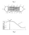
- the general structure of the exchanger is of the traditional type for gas exchangers. It comprises an enclosure 1 enclosing a bundle of tubes 2. The tubes are fixed inside the enclosure by plates 3, 4.
- the plates form a sealed wall defining the zone of the enclosure in which circulates the heat transfer gas.
- caps 5 At its ends the enclosure is closed by two caps 5, 6. These caps are attached to the enclosure in a sealed manner, by means of flanges 7, 8, 9, 10 and joints. These flanges can be disassembled to give access where appropriate to the ends of the tubes 2.
- the circulation of the heat-carrying gas and the oxygen or the gas rich in oxygen advantageously takes place countercurrently.
- the hot heat transfer gas enters the enclosure via the conduit 11, and leaves via the conduit 12 after having traveled through the circuit formed by baffles 13, 14, 15 inside the enclosure.
- the oxygen or oxygen-rich gas circulates in the tubes 2 along a substantially straight path. It enters cold end 16, and hot spring at the end 17 to be led to the burners.
- these tubes end with a flared portion.
- This arrangement facilitates the flow of oxygen and its expansion and consequently a certain slowdown.
- this flare is of frustoconical shape with an opening angle ⁇ .
- the caps, and especially the 6 disposed at the oxygen outlet are located at a distance from the ends of the tubes 2. In this way the speed of the oxygen along the walls of the cap is significantly reduced compared with to that which it presents at the exit of the tubes.
- this cap 6 is also chosen so that the progression of the hot oxygen meets the wall of the cap following a low incidence minimizing the impact.
- the wall of the cap is, for example, at an angle of approximately 20 to 30 degrees with respect to the direction of the tubes 2.
- the section of the cap is gradually reduced to the connection with the outlet pipe.
- the sizing of the tubes and their distribution are such that the speed and pressure conditions indicated above are fulfilled for the flow rates used.
- the heat exchanger to be operated continuously for very long periods, despite the precautions to avoid wear of the elements that constitute it, it may happen that a tube no longer has the necessary seal.
- the exchanger is assembled in such a way that the faulty tube can be obstructed at both ends. The operation requires the removal of hats. After the defective tube is taken out of service, the heat exchanger is again usable with a little modified efficiency in proportion to the number of active tubes remaining.
- the sealing at the flanges of the caps 9, 10, the exchanger, or the connection of these hats with the oxygen supply or outlet pipes, is advantageously obtained by means of a metal ring seal 18, lined with an oxygen resistant material 19, 20.
- the material in question is for example mica or a compressible mineral material. Seals of this type are produced in particular by Garlock under the trade name "Vitaflex"
- the samples consist of metal alloy plates 2mm thick and 20x20mm.
- the surface condition of the samples shows a certain importance as regards the sensitivity to oxidation. For this reason one face of each of these plates is polished with an abrasive sheet of SiC up to 1200 grain. The other face is left in its original state, that resulting from industrial rolling.
- the preceding measurements simultaneously comprise the oxidation of the two faces of the sample. Since only one side is polished, the measurement of the oxidation obtained is consequently greater than that which would be observed in practice, when the surface in contact with oxygen is polished.
- the analysis of the modification of the compositions on the surface, and in particular the reduction of the Cr content, is a means of assessing the risk of formation of detachable particles.
- the presence of Cr at a content of not less than 7% guarantees the formation of a protective layer preventing the formation of scales.
- the thickness of the walls may be relatively less thick than was suggested by the prior art. Longevity simulations based on these results lead to walls for the tubes of the exchangers according to the invention, the thickness of which may not be greater than 3 mm. This thickness can even be equal to or less than 2.5mm.
- the relatively small thickness of the walls of the tubes of the exchanger promotes heat transfer and therefore increases the power available for the same exchange surface.
- an exchanger according to the invention is constituted as follows. It consists of a bundle of 40 Inconel 600 tubes. The outer diameter of the tubes is 17.2mm and the wall thickness is 2.3mm. The tubes have a length of 4000mm.
- the exchange surface in contact with oxygen is then 8.4 m 2 .
- the heat-transfer gas (from the dust-free air) enters the exchanger at a temperature of 650 ° C.
- the heat transfer gas flow rate is set at 750 Nm 3 / h.
- the oxygen flow rate is 400 Nm 3 / h. Entering at room temperature the oxygen is heated to 550 ° C.
- the speed of the oxygen in the pipes is 67 m / s, and the pressure drop in the exchanger is less than 0.15 bar.
- a safety system comprising a pressure switch, maintains the pressure in the exchanger less than 1 bar.
- the nominal power of the exchanger is 84kW, that per unit area is 9.7kW / m 2 .
- the exchanger supplies oxygen to a non-glass industrial furnace burner with a power of 2MW.
- the complete furnace is supplied with oxygen by exchangers similarly sized.
- the power of each of these exchangers is adapted to best distribute the total power required for driving the oven.
Landscapes
- Engineering & Computer Science (AREA)
- Mechanical Engineering (AREA)
- General Engineering & Computer Science (AREA)
- Chemical & Material Sciences (AREA)
- Combustion & Propulsion (AREA)
- Physics & Mathematics (AREA)
- Thermal Sciences (AREA)
- Heat-Exchange Devices With Radiators And Conduit Assemblies (AREA)
Priority Applications (2)
| Application Number | Priority Date | Filing Date | Title |
|---|---|---|---|
| EP07301030A EP1990594A1 (de) | 2007-05-10 | 2007-05-10 | Wärmetauscher für Sauerstoff und dessen Verwendung |
| PCT/EP2008/055610 WO2008141937A1 (fr) | 2007-05-10 | 2008-05-07 | Echangeur de chaleur pour oxygene et son utilisation |
Applications Claiming Priority (1)
| Application Number | Priority Date | Filing Date | Title |
|---|---|---|---|
| EP07301030A EP1990594A1 (de) | 2007-05-10 | 2007-05-10 | Wärmetauscher für Sauerstoff und dessen Verwendung |
Publications (1)
| Publication Number | Publication Date |
|---|---|
| EP1990594A1 true EP1990594A1 (de) | 2008-11-12 |
Family
ID=38596404
Family Applications (1)
| Application Number | Title | Priority Date | Filing Date |
|---|---|---|---|
| EP07301030A Withdrawn EP1990594A1 (de) | 2007-05-10 | 2007-05-10 | Wärmetauscher für Sauerstoff und dessen Verwendung |
Country Status (2)
| Country | Link |
|---|---|
| EP (1) | EP1990594A1 (de) |
| WO (1) | WO2008141937A1 (de) |
Families Citing this family (1)
| Publication number | Priority date | Publication date | Assignee | Title |
|---|---|---|---|---|
| US9851102B2 (en) | 2012-09-26 | 2017-12-26 | L'Air Liquide Société Anonyme Pour L'Étude Et L'Exploitation Des Procedes Georges Claude | Method and system for heat recovery from products of combustion and charge heating installation including the same |
Citations (6)
| Publication number | Priority date | Publication date | Assignee | Title |
|---|---|---|---|---|
| EP0068057A2 (de) * | 1981-06-26 | 1983-01-05 | Societe Chimique De La Grande Paroisse, Azote Et Produits Chimiques | Nitrationsreaktor für Kohlenwasserstoffe in der Gasphase |
| US4518811A (en) * | 1979-03-28 | 1985-05-21 | Societe Chimique De La Grande Paroisse - Azote Et Products Chimiques | Reactor for nitration of hydrocarbons in the gaseous phase under pressure |
| US6139315A (en) * | 1996-12-19 | 2000-10-31 | Sandvik Ab | Recuperator for furnaces |
| US6250916B1 (en) * | 1997-04-15 | 2001-06-26 | American Air Liquide, Inc. | Heat recovery apparatus and methods of use |
| EP1338848A2 (de) * | 2002-02-25 | 2003-08-27 | L'Air Liquide S. A. à Directoire et Conseil de Surveillance pour l'Etude et l'Exploitation des Procédés Georges Claude | Verfahren und Vorrichtung zur integrierten Luftzerlegung und Wärmerückgewinnung in einem Ofen |
| US6620969B1 (en) * | 1999-03-11 | 2003-09-16 | Nippon Shokubai Co. , Ltd. | Shell-and-tube heat exchanger and method for inhibiting polymerization in the shell-and-tube heat exchanger |
-
2007
- 2007-05-10 EP EP07301030A patent/EP1990594A1/de not_active Withdrawn
-
2008
- 2008-05-07 WO PCT/EP2008/055610 patent/WO2008141937A1/fr not_active Ceased
Patent Citations (6)
| Publication number | Priority date | Publication date | Assignee | Title |
|---|---|---|---|---|
| US4518811A (en) * | 1979-03-28 | 1985-05-21 | Societe Chimique De La Grande Paroisse - Azote Et Products Chimiques | Reactor for nitration of hydrocarbons in the gaseous phase under pressure |
| EP0068057A2 (de) * | 1981-06-26 | 1983-01-05 | Societe Chimique De La Grande Paroisse, Azote Et Produits Chimiques | Nitrationsreaktor für Kohlenwasserstoffe in der Gasphase |
| US6139315A (en) * | 1996-12-19 | 2000-10-31 | Sandvik Ab | Recuperator for furnaces |
| US6250916B1 (en) * | 1997-04-15 | 2001-06-26 | American Air Liquide, Inc. | Heat recovery apparatus and methods of use |
| US6620969B1 (en) * | 1999-03-11 | 2003-09-16 | Nippon Shokubai Co. , Ltd. | Shell-and-tube heat exchanger and method for inhibiting polymerization in the shell-and-tube heat exchanger |
| EP1338848A2 (de) * | 2002-02-25 | 2003-08-27 | L'Air Liquide S. A. à Directoire et Conseil de Surveillance pour l'Etude et l'Exploitation des Procédés Georges Claude | Verfahren und Vorrichtung zur integrierten Luftzerlegung und Wärmerückgewinnung in einem Ofen |
Also Published As
| Publication number | Publication date |
|---|---|
| WO2008141937A1 (fr) | 2008-11-27 |
Similar Documents
| Publication | Publication Date | Title |
|---|---|---|
| EP2824409B1 (de) | Verfahren zum Versorgen von Brennern eines Glasschmelzofens | |
| EP2294019B1 (de) | Einspeisung für heissen sauerstoffbrenner | |
| EP1920192B1 (de) | Verfahren zum vorwärmen von brennstoff und treibstoff und brennstoff für sauerstoff-brenner mit anlagen zum vorwärmen von verbrennungsluft | |
| EP3166717A1 (de) | In einem additivverfahren hergestellter austauscher und/oder reaktoraustauscher | |
| EP3087041B1 (de) | Verbrennung mit verbesserter wärmerückgewinnung | |
| FR2917155A1 (fr) | Combustion diluee | |
| EP2935133B1 (de) | Energierückgewinnung aus rauchgas aus einem schmelzofen mit einer gasturbine und wärmetauschern | |
| WO2008141937A1 (fr) | Echangeur de chaleur pour oxygene et son utilisation | |
| EP1001237A1 (de) | Beheizungsverfahren eines kontinuierlich arbeitenden Ofens für Stahl Produkte und kontinuierlich arbeitender Ofen | |
| FR3039888A1 (fr) | Echangeur comprenant des canaux presentant une faible epaisseur de paroi entre eux | |
| EP3482131B1 (de) | Verfahren zum vorheizen eines fluids vor einem ofen | |
| EP3389883A1 (de) | Verfahren und anlage zur abfallbehandlung | |
| EP2705003B1 (de) | Verfahren zum glasschmelzen in einem ofen | |
| EP2705002B1 (de) | Verfahren zum glasschmelzen in einem ofen | |
| WO2010000762A2 (fr) | Oxy-bruleur a combustion etagee | |
| FR2675399A1 (fr) | Reacteur-echangeur de chaleur sous pression comportant des moyens de combustion controlee. | |
| FR2675499A1 (fr) | Procede et dispositif de vapocraquage d'une charge hydrocarbonee comportant un generateur a gaz et un reacteur echangeur de chaleur. | |
| FR2675498A1 (fr) | Procede et dispositif de vapocraquage d'une charge hydrocarbonee comportant une phase de chauffage dans un reacteur echangeur de chaleur. |
Legal Events
| Date | Code | Title | Description |
|---|---|---|---|
| PUAI | Public reference made under article 153(3) epc to a published international application that has entered the european phase |
Free format text: ORIGINAL CODE: 0009012 |
|
| AK | Designated contracting states |
Kind code of ref document: A1 Designated state(s): AT BE BG CH CY CZ DE DK EE ES FI FR GB GR HU IE IS IT LI LT LU LV MC MT NL PL PT RO SE SI SK TR |
|
| AX | Request for extension of the european patent |
Extension state: AL BA HR MK RS |
|
| 17P | Request for examination filed |
Effective date: 20090512 |
|
| AKX | Designation fees paid |
Designated state(s): AT BE BG CH CY CZ DE DK EE ES FI FR GB GR HU IE IS IT LI LT LU LV MC MT NL PL PT RO SE SI SK TR |
|
| 17Q | First examination report despatched |
Effective date: 20090619 |
|
| STAA | Information on the status of an ep patent application or granted ep patent |
Free format text: STATUS: THE APPLICATION IS DEEMED TO BE WITHDRAWN |
|
| 18D | Application deemed to be withdrawn |
Effective date: 20091230 |