EP1990606A1 - Appareil de photo stero - Google Patents
Appareil de photo stero Download PDFInfo
- Publication number
- EP1990606A1 EP1990606A1 EP07714902A EP07714902A EP1990606A1 EP 1990606 A1 EP1990606 A1 EP 1990606A1 EP 07714902 A EP07714902 A EP 07714902A EP 07714902 A EP07714902 A EP 07714902A EP 1990606 A1 EP1990606 A1 EP 1990606A1
- Authority
- EP
- European Patent Office
- Prior art keywords
- camera
- stay
- openings
- attachment portion
- stereo camera
- Prior art date
- Legal status (The legal status is an assumption and is not a legal conclusion. Google has not performed a legal analysis and makes no representation as to the accuracy of the status listed.)
- Granted
Links
Images



Classifications
-
- H—ELECTRICITY
- H04—ELECTRIC COMMUNICATION TECHNIQUE
- H04N—PICTORIAL COMMUNICATION, e.g. TELEVISION
- H04N13/00—Stereoscopic video systems; Multi-view video systems; Details thereof
- H04N13/20—Image signal generators
- H04N13/204—Image signal generators using stereoscopic image cameras
-
- G—PHYSICS
- G01—MEASURING; TESTING
- G01C—MEASURING DISTANCES, LEVELS OR BEARINGS; SURVEYING; NAVIGATION; GYROSCOPIC INSTRUMENTS; PHOTOGRAMMETRY OR VIDEOGRAMMETRY
- G01C3/00—Measuring distances in line of sight; Optical rangefinders
- G01C3/10—Measuring distances in line of sight; Optical rangefinders using a parallactic triangle with variable angles and a base of fixed length in the observation station, e.g. in the instrument
- G01C3/18—Measuring distances in line of sight; Optical rangefinders using a parallactic triangle with variable angles and a base of fixed length in the observation station, e.g. in the instrument with one observation point at each end of the base
-
- G—PHYSICS
- G01—MEASURING; TESTING
- G01S—RADIO DIRECTION-FINDING; RADIO NAVIGATION; DETERMINING DISTANCE OR VELOCITY BY USE OF RADIO WAVES; LOCATING OR PRESENCE-DETECTING BY USE OF THE REFLECTION OR RERADIATION OF RADIO WAVES; ANALOGOUS ARRANGEMENTS USING OTHER WAVES
- G01S11/00—Systems for determining distance or velocity not using reflection or reradiation
- G01S11/12—Systems for determining distance or velocity not using reflection or reradiation using electromagnetic waves other than radio waves
-
- G—PHYSICS
- G03—PHOTOGRAPHY; CINEMATOGRAPHY; ANALOGOUS TECHNIQUES USING WAVES OTHER THAN OPTICAL WAVES; ELECTROGRAPHY; HOLOGRAPHY
- G03B—APPARATUS OR ARRANGEMENTS FOR TAKING PHOTOGRAPHS OR FOR PROJECTING OR VIEWING THEM; APPARATUS OR ARRANGEMENTS EMPLOYING ANALOGOUS TECHNIQUES USING WAVES OTHER THAN OPTICAL WAVES; ACCESSORIES THEREFOR
- G03B17/00—Details of cameras or camera bodies; Accessories therefor
- G03B17/56—Accessories
-
- G—PHYSICS
- G03—PHOTOGRAPHY; CINEMATOGRAPHY; ANALOGOUS TECHNIQUES USING WAVES OTHER THAN OPTICAL WAVES; ELECTROGRAPHY; HOLOGRAPHY
- G03B—APPARATUS OR ARRANGEMENTS FOR TAKING PHOTOGRAPHS OR FOR PROJECTING OR VIEWING THEM; APPARATUS OR ARRANGEMENTS EMPLOYING ANALOGOUS TECHNIQUES USING WAVES OTHER THAN OPTICAL WAVES; ACCESSORIES THEREFOR
- G03B35/00—Stereoscopic photography
- G03B35/08—Stereoscopic photography by simultaneous recording
Definitions
- the invention relates to a stereo camera which estimates a distance to a preceding object while processing an azimuth difference of the two images taken by right and left cameras.
- a stereo camera which estimates a distance from a vehicle to a preceding object while processing the azimuth difference of the two images taken by the right and left cameras that are arranged in the front portion of the vehicle with the optical axes set apart at a predetermined distance (base length).
- This stereo camera is mounted on a vehicle as a distance measuring system for measuring a distance to a target and used as a collision avoidance system for warning of a distance between two vehicles and warning of an obstacle.
- Fig. 7 is a perspective view of the conventional stereo camera.
- the conventional stereo camera has right camera 21, left camera 22, camera stay 23 which holds right camera 21 and left camera 22 at predetermined positions, and attachment portion 24 for fixing camera stay 23 to attached body portion 25.
- the stereo camera is fixed to attached body portion 25 by means of three screws through openings 26, 27, and 28 bored in the attachment portion 24.
- an error of a measured distance depends on the accurate disposition of two cameras on the both sides of a stereo camera.
- the position of the two cameras changes or the optical axis of the camera is deviated from a predetermined position, there occurs an error of a measured distance, which deteriorates reliability in a collision avoidance system (for example, refer to Patent Document 1).
- Attached body portion 25 of a vehicle with the stereo camera mounted is easy to rise in temperature because of receiving direct sunlight, for example, during parking. Since the conventional stereo camera is fixed to a vehicle with two screws on the side close to camera stay 23, the portion fixed to the attached body portion by openings 26 and 27 bored in attachment portion 24 is restrained by the interval of opening 29 and opening 30 of attached body portion 25. Since camera stay 23 is not directly fixed to a car body and it spontaneously expands, a difference of expansion between attachment portion 24 and camera stay 23 integrally formed causes a deformation of the portion of camera stay 23 and a deviation of the base length and the optical axis in the right and left cameras, which deteriorates distance measurement accuracy.
- Patent Document 1 Japanese Patent Unexamined Publication No. 2001-88623
- the invention provides a stereo camera capable of keeping measurement accuracy while preventing deviation in the base length and the optical axis of a camera under a sever environment.
- the stereo camera according to the invention has: a right camera and a left camera, a camera stay which holds the right camera and the left camera at predetermined positions, and an attachment portion having openings for fixing the camera stay to a vehicle, in which the respective centers of the openings are positioned at a plurality of virtual lines parallel to a base line connecting the right camera and the left camera, a plurality of the openings are arranged on a virtual parallel line far from the camera stay, and one opening is arranged on a virtual parallel line closer to the camera stay than the faraway virtual parallel line.
- the number of the plural openings is two, which forms an isosceles triangle with the one opening, and the center of the one opening is positioned at an apex of the isosceles triangle having two sides of equal length.
- the center of the one opening is positioned in the middle of the base length connecting the right camera and the left camera.
- the camera stay and the attachment portion are integrally formed.
- Fig. 1 is a perspective view of the stereo camera according to the embodiment of the invention.
- the stereo camera of the invention comprises right camera 1, left camera 2, camera stay 3 for holding right camera 1 and left camera 2 at predetermined positions, and attachment portion 4 having openings for fixing camera stay 3 to a vehicle.
- the centers of openings 5, 6, and 7 are positioned on a plurality of virtual lines (in Fig. 1 , two dotted lines AA' and BB') parallel to the base line connecting right camera 1 and left camera 2.
- a plural number of openings are arranged on the virtual parallel line AA' far away from camera stay 3 and one opening is arranged on the virtual parallel line BB' closer to camera stay 3 than the faraway virtual parallel line AA'.
- Camera stay 3 is a rectangular plate, having attachment portion 4 protruding from the rear end surface in the middle portion. Camera stay 3 and attachment portion 4 are integrally formed by light, rigid, and good heat conductive aluminum base alloy.
- This integral form realizes a stereo camera having an accuracy of attachment free from error at the assembling time compared with the case of forming camera stay 3 and attachment portion 4 separately.
- Use of good heat conductive aluminum base alloy contributes to save the weight of the stereo camera. It is effective in releasing heat from a photographing circuit board installed within camera stay 3, thereby realizing a reliable stereo camera.
- Pitch shows the rotation around the base line connecting right camera 1 and left camera 2.
- Roll shows the rotation of right camera 1 and left camera 2 in the direction of optical axis.
- Yaw shows the rotation around the direction vertical to the plain surface formed by the base line and the optical axes of right camera 1 and left camera 2.
- Attachment portion 4 has openings 5, 6, and 7 for passing the screws.
- openings 6 and 7 are positioned at a predetermined space and opening 5 is positioned in the middle of opening 6 and opening 7 in the direction of the base line. Openings 5, 6, and 7 are arranged to form an isosceles triangle having two sides of equal length around the center of opening 5.
- Fixing attachment portion 4 to camera stay 3 through this arrangement of the openings prevents from rotation in three directions; Pitch, Roll, and Yaw and deviation of the base length and the optical axis in the right and left cameras, thereby keeping measurement accuracy.
- the centers of openings 5, 6, and 7 are positioned on the two virtual lines parallel to the base line connecting right camera 1 and left camera 2.
- the number of openings arranged on the virtual parallel line AA' far from camera stay 3 is two and the number of opening arranged on the virtual parallel line BB' closer to camera stay 3 than the faraway virtual parallel line AA' is one.
- attachment portion 4 is not restrained by the attachment pitch on the side of attached car body portion 11 nor affected by the thermal expansion on attached car body portion 11 described later. Since attachment portion 4 expands integrally with camera stay 3 and camera stay 3 is not deformed, there occurs no deviation of the base length and the optical axis in the right and left cameras and accuracy of distance measurement can be kept.
- the center of opening 5 on the side of camera stay 3 in the direction of the camera base length is positioned in the middle of right camera 1 and left camera 2 on the camera base line. Since this arrangement can support right camera 1 and left camera 2 equally, it is possible to secure stability against vibration and impact at a running time.
- Fig. 2 is a view showing the state of attaching the stereo camera to a car body according to the embodiment of the invention.
- attached car body portion 11 has openings 12, 13, and 14 on the side of car body.
- the stereo camera is screwed up and fastened to attached car body portion 11 by three screws 8, 9, and 10 through openings 5, 6, and 7 provided on attachment portion 4.
- the stereo camera mounted on a vehicle takes in the images of a preceding object through respective image pickup devices inside right camera 1 and left camera 2.
- An image processing substrate (not illustrated) installed inside camera stay 3 takes in the images at a predetermined timing through the two image pickup devices inside the right and left cameras and processes deviation of the images taken at the both sides, hence to calculate a distance to the preceding object.
- the stereo camera detects a distance between the preceding vehicle and itself and also detects a distance to a preceding obstacle.
- the vehicle runs within reach of a predetermined distance, it issues a warning through sound or light to a driver.
- Fig. 3 is an arrangement view of opening 5 on attachment portion 4 of the stereo camera according to the embodiment of the invention for use in the experiment. Opening 5 is positioned near camera stay 3 and openings 6 and 7 are positioned far from camera stay 3. Openings 6 and 7 are positioned at an interval and opening 5 is positioned in the middle of openings 6 and 7 in the base line direction.
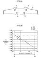
- Fig. 5 is an arrangement view of openings 15 to 18 on attachment portion 14 of the stereo camera of the comparison example.
- the shape and size of attachment portion 14 is the same as that of attachment portion 4 according to the embodiment of the invention.
- Openings 17 and 18 are disposed at the same positions as openings 6 and 7 on attachment portion 4 according to the embodiment of the invention.
- the comparison example is different from attachment portion 4 according to the embodiment of the invention in that two openings 15 and 16 are positioned near the camera stay, but the other conditions are the same.
- Fig. 4 is a view showing a relation between the surrounding temperature and the displacement amount of angle of the both cameras when the stereo camera according to the embodiment of the invention in Fig. 3 is attached to a vehicle.
- a horizontal axis indicates the surrounding temperature of the stereo camera.
- a vertical axis indicates the angle displacement amount in the directions of Yaw, Pitch, and Roll between right camera 1 and left camera 2 with the position of right camera 1 used as a reference point.
- the same rotation of the both cameras with respect to the direction of the base line direction and the optical axis causes no deviation in the base line and the optical axis, in a relative positional relation.
- the rotational direction is different between the both cameras and there occurs some angle displacement amount, there also occurs deviation in the base line and the optical axis, which deteriorates the accuracy of distance measurement.
- the angle displacement amount of the both cameras is used as a parameter to estimate distance measurement accuracy.
- the stereo camera according to the embodiment of the invention uses image pickup device 1 of 1/3 size and 40 hundred thousand pixels.
- One pixel pitch is 6.35 ⁇ m and in order to secure the distance measurement accuracy, it is necessary to suppress the deviation between the two images taken through the both cameras below 6.35 ⁇ m corresponding to the pitch for one pixel of image pickup device 1. Since the angle of view of the both cameras used for the stereo camera according to the embodiment of the invention is 43° and the length of acceptance surface of image pickup device 1 is 4.9 mm, the focal length of the lens is 6.2 mm. When the pitch for one pixel is converted into the angle in the Yaw direction, the pitch 6.35 ⁇ m is divided by the focal length of the lens 6.2 mm, to get 0.06°.
- the angle displacement amount in the Yaw direction has to be suppressed below 0.06° in the range of -40°C to 85°C as illustrated by the dotted line in Fig. 4 .
- the angle displacement amount at this time is adjusted to 0°.
- left camera 2 changes in the direction of increasing the rotation angle shown by the arrow in the Yaw direction in Fig. 1 (the axis direction vertical to the plain surface formed by the base line and the optical axis of the stereo camera).
- left camera 2 changes in the direction of increasing the rotation angle in the inverse direction to the arrow of the Yaw direction in Fig. 1 , with right camera 1 as a reference point.
- the angle displacement amount of the both has a linear characteristic varying at a constant ratio according to the surrounding temperature.
- the displacement amount of the rotation in the Yaw direction at the surrounding temperature -40°C is 0.0464° as shown in Fig. 4 and this becomes no problem practically.
- the angle displacement amount has a linear relation with the surrounding temperature, varying at a constant ratio. Therefore, even at 85°C which is symmetric to 25°C in the temperature change, it is assumed that the angle displacement amount of Yaw in the both cameras is almost the same.
- Fig. 6 is a view showing the relation between the surrounding temperature and the angle displacement amount of the both cameras in the case of attaching the stereo camera of the comparison example in Fig. 5 to a vehicle.
- the scale of the horizontal axis and the vertical axis in Fig. 6 is the same as that in Fig. 4 .
- the angle displacement amount between right camera 1 and left camera 2 in the Yaw direction at -40°C with the position of right camera 1 as a reference point is 0.0605°.
- This angle displacement amount is about 1.3 times as much as that in the case of attaching the stereo camera according to the embodiment of the invention to a vehicle, which decreases the measurement accuracy extremely.
- the respective centers of openings are positioned at a plurality of virtual lines parallel to the base line connecting right camera and left camera, the number of openings arranged on the virtual parallel line AA' far from the camera stay is set at two, and the number of openings arranged on the virtual parallel line BB' close to the camera stay is set at one. Therefore, positional deviation between the two cameras can be suppressed and accurate distance measurement can be realized.
- the stereo camera according to the invention can prevent the camera stay from deforming due to a difference of expansion between the attachment portion and the camera stay and prevent from deviation in the base length and the optical axis of the both cameras, hence to keep the distance measurement accuracy. It is useful as a stereo camera for estimating a distance to a preceding object while processing an azimuth difference between the two images taken by the cameras on the both sides.
Landscapes
- Physics & Mathematics (AREA)
- General Physics & Mathematics (AREA)
- Engineering & Computer Science (AREA)
- Electromagnetism (AREA)
- Radar, Positioning & Navigation (AREA)
- Remote Sensing (AREA)
- Multimedia (AREA)
- Signal Processing (AREA)
- Measurement Of Optical Distance (AREA)
- Stereoscopic And Panoramic Photography (AREA)
- Accessories Of Cameras (AREA)
- Length Measuring Devices By Optical Means (AREA)
Applications Claiming Priority (2)
| Application Number | Priority Date | Filing Date | Title |
|---|---|---|---|
| JP2006049673A JP4848795B2 (ja) | 2006-02-27 | 2006-02-27 | ステレオカメラ |
| PCT/JP2007/053470 WO2007097444A1 (fr) | 2006-02-27 | 2007-02-26 | appareil de photo stero |
Publications (3)
| Publication Number | Publication Date |
|---|---|
| EP1990606A1 true EP1990606A1 (fr) | 2008-11-12 |
| EP1990606A4 EP1990606A4 (fr) | 2010-09-22 |
| EP1990606B1 EP1990606B1 (fr) | 2012-01-25 |
Family
ID=38437479
Family Applications (1)
| Application Number | Title | Priority Date | Filing Date |
|---|---|---|---|
| EP07714902A Ceased EP1990606B1 (fr) | 2006-02-27 | 2007-02-26 | Appareil de photo stereo |
Country Status (6)
| Country | Link |
|---|---|
| US (1) | US20090135246A1 (fr) |
| EP (1) | EP1990606B1 (fr) |
| JP (1) | JP4848795B2 (fr) |
| KR (1) | KR100917514B1 (fr) |
| CN (1) | CN101326424B (fr) |
| WO (1) | WO2007097444A1 (fr) |
Cited By (1)
| Publication number | Priority date | Publication date | Assignee | Title |
|---|---|---|---|---|
| CN110546041B (zh) * | 2017-04-19 | 2023-07-21 | 五十铃自动车株式会社 | 车载用照相机 |
Families Citing this family (28)
| Publication number | Priority date | Publication date | Assignee | Title |
|---|---|---|---|---|
| US20080001727A1 (en) * | 2004-11-15 | 2008-01-03 | Hitachi, Ltd. | Stereo Camera |
| JP2009068906A (ja) * | 2007-09-11 | 2009-04-02 | Panasonic Corp | 距離測定装置 |
| DE102009031650B4 (de) * | 2009-07-03 | 2024-05-29 | Volkswagen Ag | Verfahren zur Erweiterung eines Kamerasystems, Kamerasystem, Fahrerassistenzsysem und entsprechendes Fahrzeug |
| JP5440927B2 (ja) * | 2009-10-19 | 2014-03-12 | 株式会社リコー | 測距カメラ装置 |
| JP2011221506A (ja) * | 2010-03-26 | 2011-11-04 | Panasonic Corp | 撮像装置 |
| JP2013545347A (ja) * | 2010-10-04 | 2013-12-19 | ティ.ケイ.ホールディングス、インコーポレイテッド | カメラシステム |
| WO2012132086A1 (fr) * | 2011-03-25 | 2012-10-04 | 三洋電機株式会社 | Dispositif d'acquisition d'informations et dispositif de détection d'objet ayant un dispositif d'acquisition d'informations monté dans celui-ci |
| WO2013014717A1 (fr) * | 2011-07-26 | 2013-01-31 | パナソニック株式会社 | Dispositif de formation d'images |
| CN103052915B (zh) * | 2011-07-26 | 2015-09-30 | 松下电器产业株式会社 | 摄像装置 |
| JP5792126B2 (ja) * | 2012-06-21 | 2015-10-07 | 住友建機株式会社 | 建設機械 |
| JP5793122B2 (ja) | 2012-07-31 | 2015-10-14 | 日立オートモティブシステムズ株式会社 | 車載画像処理装置 |
| DE102013104163A1 (de) * | 2013-04-24 | 2014-10-30 | Conti Temic Microelectronic Gmbh | Stereokamerasystem |
| CN104570574A (zh) * | 2013-10-18 | 2015-04-29 | 宁夏先锋软件有限公司 | 一种利用2d图像自动成像的3d成像仪 |
| KR101698783B1 (ko) * | 2013-12-16 | 2017-01-23 | 엘지전자 주식회사 | 스테레오 카메라 및 이를 구비한 차량 |
| JP2016014564A (ja) * | 2014-07-01 | 2016-01-28 | 株式会社リコー | 撮像ユニット |
| KR101668834B1 (ko) * | 2014-10-02 | 2016-10-25 | 씨제이씨지브이 주식회사 | 다중 카메라 촬영용 리그 |
| JP6158258B2 (ja) * | 2015-08-07 | 2017-07-05 | 日立オートモティブシステムズ株式会社 | 車載画像処理装置 |
| KR102316448B1 (ko) | 2015-10-15 | 2021-10-25 | 삼성전자주식회사 | 이미지 장치 및 그것의 뎁쓰 계산 방법 |
| JP6621716B2 (ja) * | 2016-08-02 | 2019-12-18 | 日立オートモティブシステムズ株式会社 | ステレオカメラ |
| JP7020844B2 (ja) | 2017-09-29 | 2022-02-16 | 株式会社デンソー | 車載カメラ装置 |
| JP6939353B2 (ja) | 2017-09-29 | 2021-09-22 | 株式会社デンソー | 車載カメラ装置 |
| JP7027844B2 (ja) | 2017-11-29 | 2022-03-02 | 株式会社デンソー | カメラモジュール |
| JP1610727S (fr) | 2018-03-21 | 2018-08-06 | ||
| JP1610726S (fr) * | 2018-03-21 | 2018-08-06 | ||
| JP1613901S (fr) * | 2018-03-21 | 2018-09-18 | ||
| JP2021103268A (ja) * | 2019-12-25 | 2021-07-15 | 株式会社リコー | 支持装置及び撮像装置 |
| US11740078B2 (en) * | 2020-07-21 | 2023-08-29 | Argo AI, LLC | Enhanced sensor alignment |
| CN113306497B (zh) * | 2021-05-27 | 2023-08-01 | 新石器慧通(北京)科技有限公司 | 一种摄像头固定支架和无人车 |
Family Cites Families (7)
| Publication number | Priority date | Publication date | Assignee | Title |
|---|---|---|---|---|
| CN2157530Y (zh) * | 1993-02-13 | 1994-02-23 | 江门雄霸立体光学器材有限公司 | 小型四镜头立体照相机 |
| CN1176403A (zh) * | 1996-09-06 | 1998-03-18 | 稻叶稔 | 立体摄影机 |
| JP3603929B2 (ja) * | 1998-04-17 | 2004-12-22 | 京セラ株式会社 | 車載用ステレオカメラの支持装置 |
| JP3877475B2 (ja) * | 1999-09-22 | 2007-02-07 | 富士重工業株式会社 | 車載カメラの取付構造 |
| JP2003335180A (ja) * | 2002-05-17 | 2003-11-25 | Fuji Heavy Ind Ltd | センサの支持構造およびその組付方法 |
| DE10237481A1 (de) * | 2002-08-16 | 2004-04-01 | Hella Kg Hueck & Co. | Kameraanordnung für Kraftfahrzeuge |
| JP4265756B2 (ja) * | 2003-07-02 | 2009-05-20 | 富士重工業株式会社 | 車載カメラの取り付け構造 |
-
2006
- 2006-02-27 JP JP2006049673A patent/JP4848795B2/ja not_active Expired - Fee Related
-
2007
- 2007-02-26 KR KR1020077029733A patent/KR100917514B1/ko not_active Expired - Fee Related
- 2007-02-26 WO PCT/JP2007/053470 patent/WO2007097444A1/fr not_active Ceased
- 2007-02-26 CN CN200780000561XA patent/CN101326424B/zh not_active Expired - Fee Related
- 2007-02-26 US US11/915,672 patent/US20090135246A1/en not_active Abandoned
- 2007-02-26 EP EP07714902A patent/EP1990606B1/fr not_active Ceased
Cited By (1)
| Publication number | Priority date | Publication date | Assignee | Title |
|---|---|---|---|---|
| CN110546041B (zh) * | 2017-04-19 | 2023-07-21 | 五十铃自动车株式会社 | 车载用照相机 |
Also Published As
| Publication number | Publication date |
|---|---|
| JP4848795B2 (ja) | 2011-12-28 |
| EP1990606B1 (fr) | 2012-01-25 |
| JP2007225543A (ja) | 2007-09-06 |
| CN101326424A (zh) | 2008-12-17 |
| CN101326424B (zh) | 2010-06-09 |
| EP1990606A4 (fr) | 2010-09-22 |
| WO2007097444A1 (fr) | 2007-08-30 |
| US20090135246A1 (en) | 2009-05-28 |
| KR100917514B1 (ko) | 2009-09-16 |
| KR20080009761A (ko) | 2008-01-29 |
Similar Documents
| Publication | Publication Date | Title |
|---|---|---|
| EP1990606B1 (fr) | Appareil de photo stereo | |
| US9854225B2 (en) | Imaging unit including a chassis and heat transfer member | |
| EP3518033B1 (fr) | Dispositif d'imagerie | |
| US11203313B2 (en) | Sensor attachment structure and moving body | |
| US10931932B2 (en) | Supporting housing for stereo camera and circuit board | |
| US11067875B2 (en) | Stereo camera device | |
| JP2009068906A (ja) | 距離測定装置 | |
| EP1086859A1 (fr) | Chassis de montage de caméras sur un véhicule | |
| US11543616B2 (en) | In-vehicle image pickup device | |
| EP2952388A1 (fr) | Appareil de montage pour le montage d'un capteur automobile | |
| JP3603929B2 (ja) | 車載用ステレオカメラの支持装置 | |
| WO2014050282A1 (fr) | Dispositif de caméra stéréoscopique | |
| JP2014065393A (ja) | ステレオカメラ装置 | |
| EP3796085A1 (fr) | Dispositif pour appareil de prise de vues | |
| JP7575636B1 (ja) | 撮像装置 | |
| JP7382272B2 (ja) | 撮像装置の製造方法および撮像装置 | |
| JP3235652U (ja) | 回路板アセンブリー、画像受信装置及びレーザーレーダー | |
| EP4589970A1 (fr) | Appareil de commande, appareil de capture d'image, système de commande, appareil mobile, procédé de commande et programme | |
| CN214728535U (zh) | 传感器固定装置及行驶设备 | |
| EP4130833B1 (fr) | Structure de module de caméra | |
| JPH1163964A (ja) | 移動体の挙動検出方法および検出装置 | |
| JP7382271B2 (ja) | 撮像装置 | |
| JP2026063631A (ja) | センサ装置 |
Legal Events
| Date | Code | Title | Description |
|---|---|---|---|
| PUAI | Public reference made under article 153(3) epc to a published international application that has entered the european phase |
Free format text: ORIGINAL CODE: 0009012 |
|
| 17P | Request for examination filed |
Effective date: 20071122 |
|
| AK | Designated contracting states |
Kind code of ref document: A1 Designated state(s): DE FR GB IT |
|
| RAP1 | Party data changed (applicant data changed or rights of an application transferred) |
Owner name: PANASONIC CORPORATION |
|
| DAX | Request for extension of the european patent (deleted) | ||
| RBV | Designated contracting states (corrected) |
Designated state(s): DE FR GB IT |
|
| A4 | Supplementary search report drawn up and despatched |
Effective date: 20100825 |
|
| RIC1 | Information provided on ipc code assigned before grant |
Ipc: G03B 17/56 20060101ALI20110413BHEP Ipc: G01C 3/06 20060101AFI20110413BHEP Ipc: B60R 1/00 20060101ALI20110413BHEP Ipc: G03B 35/08 20060101ALI20110413BHEP Ipc: B60R 21/00 20060101ALI20110413BHEP |
|
| GRAP | Despatch of communication of intention to grant a patent |
Free format text: ORIGINAL CODE: EPIDOSNIGR1 |
|
| RIN1 | Information on inventor provided before grant (corrected) |
Inventor name: MATSUSHIMA,YUKIHIRO C/O PANASONIC CORPORATION Inventor name: INAGAKI,TATSUHIKO C/O PANASONIC CORPORATION Inventor name: UCHIYAMA, HIROO C/O PANASONIC CORPORATION |
|
| GRAS | Grant fee paid |
Free format text: ORIGINAL CODE: EPIDOSNIGR3 |
|
| GRAA | (expected) grant |
Free format text: ORIGINAL CODE: 0009210 |
|
| AK | Designated contracting states |
Kind code of ref document: B1 Designated state(s): DE FR GB IT |
|
| REG | Reference to a national code |
Ref country code: GB Ref legal event code: FG4D |
|
| REG | Reference to a national code |
Ref country code: DE Ref legal event code: R096 Ref document number: 602007020227 Country of ref document: DE Effective date: 20120322 |
|
| PG25 | Lapsed in a contracting state [announced via postgrant information from national office to epo] |
Ref country code: IT Free format text: LAPSE BECAUSE OF FAILURE TO SUBMIT A TRANSLATION OF THE DESCRIPTION OR TO PAY THE FEE WITHIN THE PRESCRIBED TIME-LIMIT Effective date: 20120125 |
|
| PLBE | No opposition filed within time limit |
Free format text: ORIGINAL CODE: 0009261 |
|
| STAA | Information on the status of an ep patent application or granted ep patent |
Free format text: STATUS: NO OPPOSITION FILED WITHIN TIME LIMIT |
|
| GBPC | Gb: european patent ceased through non-payment of renewal fee |
Effective date: 20120425 |
|
| 26N | No opposition filed |
Effective date: 20121026 |
|
| PG25 | Lapsed in a contracting state [announced via postgrant information from national office to epo] |
Ref country code: GB Free format text: LAPSE BECAUSE OF NON-PAYMENT OF DUE FEES Effective date: 20120425 |
|
| REG | Reference to a national code |
Ref country code: DE Ref legal event code: R097 Ref document number: 602007020227 Country of ref document: DE Effective date: 20121026 |
|
| REG | Reference to a national code |
Ref country code: FR Ref legal event code: PLFP Year of fee payment: 10 |
|
| REG | Reference to a national code |
Ref country code: FR Ref legal event code: PLFP Year of fee payment: 11 |
|
| REG | Reference to a national code |
Ref country code: FR Ref legal event code: PLFP Year of fee payment: 12 |
|
| REG | Reference to a national code |
Ref country code: DE Ref legal event code: R084 Ref document number: 602007020227 Country of ref document: DE |
|
| PGFP | Annual fee paid to national office [announced via postgrant information from national office to epo] |
Ref country code: FR Payment date: 20210429 Year of fee payment: 16 |
|
| PGFP | Annual fee paid to national office [announced via postgrant information from national office to epo] |
Ref country code: DE Payment date: 20210429 Year of fee payment: 16 |
|
| REG | Reference to a national code |
Ref country code: DE Ref legal event code: R119 Ref document number: 602007020227 Country of ref document: DE |
|
| PG25 | Lapsed in a contracting state [announced via postgrant information from national office to epo] |
Ref country code: FR Free format text: LAPSE BECAUSE OF NON-PAYMENT OF DUE FEES Effective date: 20230228 Ref country code: DE Free format text: LAPSE BECAUSE OF NON-PAYMENT OF DUE FEES Effective date: 20230901 |