EP1990624B1 - Vorrichtung und Verfahren zur Bewertung eines optischen Systems - Google Patents
Vorrichtung und Verfahren zur Bewertung eines optischen Systems Download PDFInfo
- Publication number
- EP1990624B1 EP1990624B1 EP08008432.0A EP08008432A EP1990624B1 EP 1990624 B1 EP1990624 B1 EP 1990624B1 EP 08008432 A EP08008432 A EP 08008432A EP 1990624 B1 EP1990624 B1 EP 1990624B1
- Authority
- EP
- European Patent Office
- Prior art keywords
- image
- point
- optical system
- distribution
- relative distance
- Prior art date
- Legal status (The legal status is an assumption and is not a legal conclusion. Google has not performed a legal analysis and makes no representation as to the accuracy of the status listed.)
- Active
Links
Images





Classifications
-
- G—PHYSICS
- G01—MEASURING; TESTING
- G01M—TESTING STATIC OR DYNAMIC BALANCE OF MACHINES OR STRUCTURES; TESTING OF STRUCTURES OR APPARATUS, NOT OTHERWISE PROVIDED FOR
- G01M11/00—Testing of optical apparatus; Testing structures by optical methods not otherwise provided for
- G01M11/02—Testing optical properties
- G01M11/0228—Testing optical properties by measuring refractive power
-
- G—PHYSICS
- G01—MEASURING; TESTING
- G01M—TESTING STATIC OR DYNAMIC BALANCE OF MACHINES OR STRUCTURES; TESTING OF STRUCTURES OR APPARATUS, NOT OTHERWISE PROVIDED FOR
- G01M11/00—Testing of optical apparatus; Testing structures by optical methods not otherwise provided for
- G01M11/02—Testing optical properties
- G01M11/0242—Testing optical properties by measuring geometrical properties or aberrations
- G01M11/0257—Testing optical properties by measuring geometrical properties or aberrations by analyzing the image formed by the object to be tested
Definitions
- the present invention relates to an optical system evaluation apparatus, which evaluates optical characteristics of an optical system to be evaluated on the basis of an image forming position of a point image formed through the optical system and an optical system evaluation method.
- the optical system when an image imaged by using an optical system is used for length measurement, the optical system is required to have high telecentricity.
- the telecentricity represents a state in which all main beams at the object side or an image side are parallel to an optical axis, regardless of the distance from the optical axis.
- an object-side telecentric optical system is used in a length measuring microscope. In this case, even if an object to be imaged is moved away from the focus position, the image forming position corresponding to an arbitrary point on the object is not changed. Thus, it is possible to measure the distance between two points on the object with high accuracy without depending on the focusing state or a placement position of the object.
- FIG. 11 shows an example of evaluating an image-side telecentric optical system.
- a pin-hole 71 as a point light source is provided on an object surface of an optical system 72 to be evaluated, and is illuminated from behind by an illumination means (not shown).
- a point image 73 as the aerial image of the pin-hole 71 is formed on the image surface of the optical system 72 to be evaluated.
- this point image 73 is small, it is difficult to measure the image forming position with the maximum intensity with high accuracy even if the point image 73 is directly imaged by an imaging device. Therefore, the image enlarged by an enlargement optical system 74 is imaged by the imaging device 75.
- the image forming position of the point image 73 can be determined by retrieving a pixel with the maximum brightness from the image region in which the enlarged image is imaged.
- images are sequentially imaged while moving the enlargement optical system 74 and the imaging device 75 in the optical axis direction (Z axis direction) of the optical system 72 to be evaluated and a pixel with the maximum brightness is retrieved from each image sequentially imaged, whereby it is possible to detect the lateral shift of the X and Y coordinates of the image forming position accompanying the change of the Z coordinates. Further, the tendency of the change of the lateral shift with respect to the Z coordinates is calculated, whereby the telecentricity corresponding to the point image 73 can be evaluated. Moreover, this measurement is applied to a plurality of the point images 73, whereby the distribution of image-side telecentricity of the optical system 72 to be evaluated can be evaluated.
- the respective positions of the enlargement optical system 74 and the imaging device 75 should be monitored by a triaxial measuring instrument.
- the image should be measured while moving the pin-hole 71 to a plurality of positions on the object surface.
- the X and Y coordinates of the pin-hole 71 should also be monitored by the length measuring instrument.
- the coma aberration influences the tendency of the change of the lateral shift of the image forming position with respect to the Z coordinates.
- the lateral shift of the image forming position is linearly changed with respect to the Z coordinates, while as the coma aberration is increased, the lateral shift is changed in a curved line.
- WO 2003/091685 A1 discloses a method and apparatus for testing optical characteristics of a Device-Under-Test (DUT).
- a wavefront from a light source is directed through a Hartmann plate, and the location of intersection of the rays of light passing through the Hartmann plate onto a measurement plane are measured at a plurality of optical path locations. Then, the DUT is located in the system and the locations of the rays on the measurement plane are again measured with the DUT forming part of the system at each of the plurality of optical paths.
- the transverse aberration due to the DUT for the ray at each measurement plane is determined by comparing the measurements of the rays for each location with and without the DUT.
- the system is video based and is under the control of a computer which uses a windowing software program to provide the user with a graphical user interface by which the various components of the system and test lenses may be characterized and operated on through functions available via the interface.
- Lens performance measurements such as line spread and modulation transfer functions can be graphically and numerically displayed in real-time and/or recorded on other output devices or as files in computer memory.
- US 5402224 discloses a method for inspecting distortion characteristics of a projection optical system to be inspected by arranging a mask formed with measurement patterns at a plurality of predetermined positions on the object surface side of the projection optical system, transferring projected images of the plurality of measurement patterns onto a photosensitive substrate arranged on the image surface side of the projection optical system, and detecting transfer images of the measurement-patterns, including: the step of exposing a mask, on which pairs of first and second measurement patterns are arranged adjacent to each other to be separated by a predetermined interval delta T in one direction at positions on the mask corresponding to a plurality of points at which distortion amounts are to be inspected in a projection view field of the projection optical system, onto the photosensitive substrate via the projection optical system; the step of exposing the mask onto the photosensitive substrate via the projection optical system after the mask and the photosensitive substrate are moved relative to each other by an amount determined by the interval delta T with respect to the state in the preceding step; the step of measuring relative displacements between overlapping images of the first and second measurement patterns at
- US 2004212680 discloses a device for determining an intensity and/or color and/or sharpness profile in each case of an optical lens system, which projects a test pattern consisting of measuring fields, wherein the projection is directed indirectly or directly in each case toward a sensor area of electronic color and brightness sensors of high resolution, whose measured signals, which are correlated to the measuring fields, are sent to a computer, which determines from these the intensity and/or color and/or sharpness profile and/or distortion propagation profile, outputs them to an image processing system for an electronic image flaw correction of images that were generated by an identical lens system, and stores them or temporarily stores them on a data.
- US 6788401 discloses a lens inspection apparatus and an inspection sheet for evaluating the resolution of a lens at low cost.
- a lens inspection apparatus can include an inspection sheet having a test pattern, a sliding holding portion for holding the inspection sheet, a light source for introducing a light beam into the test pattern of the inspection sheet held by the sliding holding portion, a rotary holding portion for holding the sliding holding portion so that the sliding holding portion can rotate in a plane, and a measuring section for capturing an image projected on a screen through the inspection sheet and a projection lens to be inspected, and subjecting the image to image processing.
- the test pattern has a measuring region in which linear light-shielding portions are arranged in stripes so as to achieve a predetermined spatial frequency. By rotating the rotary holding portion, the resolution of the test pattern in which the light-shielding portions extend in different directions can be easily evaluated.
- US 6195159 discloses a system which determines one or more properties of a lens, which includes a light source and a target pattern illuminated by the light source, which illuminates and which is substantially positioned at a first conjugate position of the lens.
- a detector including an active surface, is positioned at a second conjugate position of the lens such that an image of the target pattern is formed on the active surface.
- the detector generates an analog electrical signal based on the image and the a generator converts the electrical signal to a representative digital signal for processing.
- the detector is movable relative to the lens to test the lens at plural focus positions, and plural detector output signals correspond to a feature of the target pattern at plural focus positions.
- a memory stores computer-executable process steps
- a processor executes the process steps stored in the memory so as to obtain a modulation transfer function value of the lens based on a position of the detector with respect to the lens, a rotational orientation of the lens about its optical axis, a color of the light and the lens distortion measured at a plurality of field positions.
- DE 10328145 discloses an imaging characteristics measuring method having a measured transparent object inserted in an imaging system, wherein the light is transmitted through the object used for providing images of relatively spaced raster structures at a receiver, and evaluating of the obtained images using the known relative positions of the raster structures and the receiver and the imaging characteristics of the imaging system.
- JP 2006195790 discloses a lens distortion estimation apparatus comprising: a feature point observation part for observing an image coordinate value showing an amount of time change of each image in an image coordinate system set time-series image of the subject acquired with a camera means; a factorization processing part for creating the matrix data from the image coordinate value to restore a camera viewpoint motion of the camera means and a three-dimensional form of the subject; and a parameter estimation part for acquiring a re-projection coordinate value from a restored camera viewpoint motion and three-dimensional form to estimate a lens distortion parameter of the camera means from the re-projection coordinate value and observed image coordinate value.
- An apparatus is for evaluating optical characteristics of an optical system based on an image forming position of a point image formed through the optical system.
- the apparatus includes a point image producing unit that has a plurality of point light sources arranged in a planar form, and forms a point image through the optical system in each of the point light sources; an imaging unit that images a plurality of the point images to produce a point image distribution image; and a moving unit that changes relative distance between the optical system and the point light source or the imaging unit in an optical axis direction of the optical system.
- the apparatus also includes an imaging control unit that controls the moving unit to change the relative distance, and controls the imaging unit to image the point image distribution image in every change of the relative distance; an image axis shape calculation unit (15) that performs processing of detecting an image forming position in each different relative distance of the point image based on image information of a plurality of the point image distribution images imaged at the different relative distance, the processing including calculating a regression expression for a plurality of detected image forming positions to obtain a shape parameter of the image axis determined by the regression expression in each of the plurality of point images; and an evaluation value calculation unit that fits a characteristic distribution model function representing distribution of the optical characteristics to the shape parameter in each of the plurality of point images, and calculates an evaluation value of the optical characteristics based on the fitting characteristics distribution model function.
- a method for evaluating optical characteristics of an optical system based on an image forming position of a point image formed through the optical system.
- the method includes forming a point image through the optical system in each of a plurality of point light sources arranged in a planar form; imaging a plurality of the point images by an imaging unit to produce a point image distribution image; changing relative distance between the optical system and the point light source or the imaging unit in an optical axis direction of the optical system; and controlling the imaging unit to image the point image distribution image in every change of the relative distance.
- the method also includes performing, in each of the plurality of point images, processing for detecting an image forming position in each different relative distance of the point image based on image information of a plurality of the point image distribution images imaged at the different relative distance, the processing including calculating a regression expression for a plurality of detected image forming positions to obtain a shape parameter of the image axis determined by the regression expression in each of the plurality of point images; fitting a characteristic distribution model function representing distribution of the optical characteristics to the shape parameter; and calculating an evaluation value of the optical characteristics based on the fitting characteristics distribution model function.
- a computer program product causes a computer to perform the method according to the present invention.
- the distribution of the optical characteristics of the optical system to be evaluated can be evaluated in a short time with high accuracy, and especially, at least one distribution of the telecentricity and the coma aberration of the optical system to be evaluated can be evaluated in a short time with high accuracy.
- FIG. 1 shows relevant parts of a lens evaluation apparatus 100, which is the optical system evaluation apparatus according to the first embodiment.
- the lens evaluation apparatus 100 is provided with a sample 4 in which a plurality of pin-holes are arranged in a planar form, a light source 1 as an illumination means for illuminating the sample 4, an optical fiber 2, a light intensity uniformization part 3, a Z axis stage 5 which is a movement means for holding the sample 4 and moving the sample 4 in the Z axis direction, and an XY stage 6 for moving the sample 4 in the X axis direction and the Y axis direction.
- the lens evaluation apparatus 100 is further provided with an image forming lens 7b which constitutes a microscope optical system 7 with an objective lens 7a as an optical system to be evaluated and forms an observation image of the sample 4, a lens barrel 11 holding the image forming lens 7b therein, a rotation part 8 which is provided in a bottom part of the lens barrel 11 and rotatably holds the objective lens 7a around an optical axis 9 thereof, an imaging device 10 which is provided in an upper part of the lens barrel 11 and images the observation image of the sample 4 formed by the microscope optical system 7, an up/down movable stage 12 which supports the lens barrel 11 movably in an up and down direction, and a mirror substrate 13 which supports the up/down movable stage 12.
- an image forming lens 7b which constitutes a microscope optical system 7 with an objective lens 7a as an optical system to be evaluated and forms an observation image of the sample 4
- a lens barrel 11 holding the image forming lens 7b therein a rotation part 8 which is provided in a bottom part of the lens barrel 11 and rotat
- the light source 1 includes a white light source (not shown), a wavelength selection mechanism, and a light intensity adjustment mechanism.
- a white light source for example a halogen lamp, a xenon lamp, an LED, or the like is used.
- the wavelength selection mechanism holds a plurality of interference filters, and is constituted by using a rotation holder which can selectively provide one of the interference filters in a light path.
- the light intensity adjustment mechanism is constituted by using for example a rotatable ND filter in which the transmittance can be continuously changed within a range of 0 to 100%.
- the wavelength selection mechanism and the light intensity adjustment mechanism are driven and controlled on the basis of a control signal from a control device 14 to be described later, and can arbitrarily set (select and switch) the central wave length of the light emitted from the light source 1 and the intensity within a predetermined range.
- the wavelength selection mechanism can be constituted by using other spectroscopic device.
- the light source 1 can be constituted by using a plurality of light sources emitting light having different wavelengths.
- the light emitted by the light source 1 is guided through the optical fiber 2, and thereafter uniformed in the intensity position and the angle distribution by the light intensity uniformization part 3 to trans-illuminate the sample 4.
- the light intensity uniformization part 3 is configured by using a rod glass, a diffusion plate, or the like in which internal reflection is repeated.
- the sample 4 is a pin-hole array specimen in which a plurality of pin-holes 4a are two-dimensionally arranged as shown in FIG. 2 .
- the pin-holes 4a arranged in a lattice pattern at an equal interval in the lateral and longitudinal directions are opened on an opaque metal film 4b evaporated on a glass substrate.
- the diameters of all the pin-holes 4a are the same and are smaller than the refraction limit of the objective lens 7a. Specifically, it is equivalent to or less than the resolution of the optical system to be evaluated.
- each pin-hole 4a acts as the point light source.
- the distribution range of the pin-holes 4a is made wider than the view field of the objective lens 7a as the optical system to be evaluated.
- the Z axis stage 5 moves the sample 4 up and down in the direction of the optical axis 9 of the microscope optical system 7.
- the optical axis 9 of the microscope optical system 7 is parallel to the Z axis.
- the Z axis stage 5 is constituted by using a piezo stage including an electrostatic capacity sensor for monitoring the amount of displacement and driven and controlled on the basis of a control signal from a control device 14 to be described later, and therefore can move the sample 4 to an arbitrary Z axis position in a predetermined range.
- An XY stage 6 is a manual stage which can move the Z axis stage 5 and the sample 4 in a direction perpendicular to the optical axis 9 of the microscopic optical system 7.
- the microscopic optical system 7 forms the observation image of the sample 4 on the imaging surface of an imaging device 10.
- the imaging device 10 is a two-dimensional imaging device, such as a two-dimensional CCD having an imaging surface which is larger than the image forming range of the observation image of the sample 4 formed by the microscopic optical system 7 or can image most part of the image forming range.
- the rotation part 8 can rotate and fix the objective lens 7a at an arbitrary angle using the optical axis 9 as the rotation axis.
- the lens evaluation apparatus 100 is further provided with the control device 14 which controls the entire processing and operation of the lens evaluation apparatus 100.
- the control device 14 is provided with an image axis shape calculation unit 15, an evaluation value calculation unit 16, a storage unit 17, and a control unit 18.
- the image axis shape calculation unit 15 calculates a shape parameter of an image axis to be described later in each pin-hole image, which is the observation image of the pin-holes 4a formed by the microscope optical system 7.
- the evaluation value calculation unit 16 fits a model function representing the distribution of the optical characteristics to be evaluated to the shape parameter of the image axis in each pin-hole image and calculates the evaluation value of the optical characteristics on the basis of the fitting model function.
- the storage unit 17 stores various information.
- the control unit 18 controls the processing and operation of each unit electrically connected to each other.
- the control unit 18 is electrically connected to the image axis shape calculation unit 15, the evaluation value calculation unit 16, and the storage unit 17, and in addition, electrically connected to the light source 1, the Z axis stage 5, the imaging device 10, and the like through an interface (not shown).
- the image axis shape calculation unit 15 is provided with a fitting range setting unit 15a and an intensity distribution fitting unit 15b.
- the fitting range setting unit 15a sets a fitting range where the intensity distribution model function for detecting the maximum intensity position in each pin-hole image is fitted.
- the intensity distribution fitting unit 15b fits the intensity distribution model function to a point image region on which the pin-hole image as the point image is imaged.
- the image axis shape calculation unit 15 is further provided with an intensity position calculation unit 15c and a curve fitting unit 15d.
- the intensity position calculation unit 15c detects a planar coordinate on the observation image with the maximum intensity distribution model function and calculates the maximum intensity position of the pin-hole image on the basis of the planar coordinate.
- the curve fitting unit 15d fits a curve model function to a plurality of the maximum intensity positions calculated at different positions in the Z axis direction and obtains a coefficient of the fitting curve model function as the shape parameter of the image axis determined by the fitting curve model function.
- the storage unit 17 stores image data of the observation image imaged by the imaging device 10 and the various information such as various processing parameters used for processing performed by the control unit 18. Especially, the storage unit 17 is provided with a control program storage unit 17a in which various control programs executed by the control unit 18 are stored and a model function storage unit 17b in which various model functions used for processing performed by the image axis shape calculation unit 15 or the evaluation value calculation unit 16 are stored.
- the control unit 18 executes the control program stored in the control program storage unit 17a and thereby controls the processing and operation of each unit. Specifically, the control unit 18 changes sequentially the relative distance between the sample 4 and the microscope optical system 7 in the direction of the optical axis 9 with the aid of the Z axis stage 5 to make the imaging device 10 image the pin-hole image of each pin-hole 4a in every change of the relative distance, and, thus, to control the production of the observation image. In addition, the control unit 18 controls the calculation of the evaluation value of the optical characteristics of the microscope optical system 7 by the image axis shape calculation unit 15 and the evaluation value calculation unit 16 on the basis of the image information of the observation images imaged at a different relative distance.
- the control device 14 is provided as a computer.
- the image axis shape calculation unit 15, the evaluation value calculation unit 16, and the control unit 18 are realized by a CPU.
- the storage unit 17 is realized by using a hard disk, ROM, RAM, and the like.
- the control device 14 further includes an input unit, a display unit, and an output unit which respectively perform the input, display, and output of various information.
- an operator mounts the objective lens 7a to be evaluated on the rotation part 8, and mounts the sample 4, in which the pin-holes 4a with a pin-hole diameter suitable for the objective lens 7a are formed, on the Z axis stage 5. Then, while the image to be imaged by the imaging device 10 is monitored on the screen of the display unit of the control device 14, positioning of the sample 4 on the XY stage 6 and focusing by the up/down movable stage 12 or the Z axis stage 5 are performed. This focusing may not be performed manually, but may be performed automatically by providing, for example, an automatic focusing unit in the lens evaluation apparatus 100.
- the control unit 18 of the control device 14 controls the automatic imaging of a stack image in each wavelength.
- the stack image represents a series of the observation images (observation image group), which have been sequentially imaged at a different relative distance by the imaging device 10 while the Z axis stage 5 changes sequentially the relative distance between the sample 4 and the objective lens 7a.
- the plurality of wavelengths represent a reference wavelength, which is a reference in the evaluation of the telecentricity and a coma aberration as the optical characteristics of the microscope optical system 7, and a plurality of evaluation wavelengths to be evaluated.
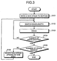
- FIG. 3 is a flowchart showing an imaging processing procedure for obtaining the stack image of a plurality of wavelengths by the execution of the imaging program by the control unit 18.
- the control unit 18 first moves the Z axis stage 5 from the focusing position (the above-mentioned position after focusing) to the bottom of the imaging range (step S101).
- the imaging range in the Z axis direction is desirably set to be several times of focal depth in such a way as to include the respective ranges of the field curvature and chromatic aberration in the longitudinal direction of the objective lens 7a to be evaluated.
- the control unit 18 switches an interference filter of the wavelength selection mechanism in the light source 1 and switches the illumination light to one wavelength in which the observation image is not imaged yet in the current Z axis stage position, among the plurality of wavelengths (step S102).
- the control unit 18 switches the light amount of the illumination light, applied to the sample 4, to an appropriate light amount by an ND filter (light amount adjustment mechanism) in the light source 1. This light amount is set in advance in such a way that the respective brightness of the stack image by the plurality of wavelengths is matched to the same level.
- control unit 18 makes the imaging device 10 image the observation image of the sample 4, and the imaging device 10 then transfers the image file to the control device 14 (step S103).
- the transferred image file is stored in the storage unit 17 in the control device 14.
- control unit 18 determines whether the steps S102 and S103 are applied to all of the plurality of wavelengths in the current Z axis stage position, in other words, determines whether the number of the wavelength used for imaging has reached a predetermined number (step S104).
- the control unit 18 proceeds to a step S105, while when the number has not reached the predetermined number (S104: No), the processing from the step S102 is repeated.
- the processings in the steps S102 and S103 are repeated until the number of the wavelength used for imaging has reached the predetermined number, whereby the image file of the observation image of each of the plurality of wavelengths in the current Z axis stage position is transferred to the control device 14 to be stored in the storage unit 17.
- the control unit 18 determines whether the number of the image file of each wavelength stored in the storage unit 17 has reached the number of the stack image covering a predetermined imaging range in the Z axis direction (step S105).
- the control unit 18 terminates the imaging processing, while when the number has not reached the number of the stack image (S105: No), the control unit 18 moves the Z axis stage 5 upward by one step (step S106), and thereafter, repeats the processing from the step S102.
- the movement amount of one step is desirably about 1/5 to 1/10 of the focal depth of the objective lens 7a to be evaluated.
- the steps S102 through S104 and S106 are repeated until the step S105 is satisfied, whereby, as the stack images, all the image files of the plurality of wavelengths for the number of stack images covering the predetermined imaging range in the Z axis direction are stored in the storage unit 17.
- the processing for sequentially switching the plurality of wavelengths every time the Z axis stage 5 is moved upward by one step to image the observation image of each wavelength is repeated, whereby the stack images with the plurality of wavelengths are simultaneously imaged.
- the drift of the position of the sample 4 progressing within a series of imaging processing time due to the change of environmental temperature or the like becomes almost the same in each wavelength. This is effective in reducing an error in the calculation of the telecentricity and the coma aberration, which is described later.
- This analysis program is a part of the control program stored in the control program storage unit 17a and controls to automatically calculate the evaluation value between the telecentricity and the coma aberration, which are the optical characteristics of the microscopic optical system 7 including the objective lens 7a, from the image file of the stack image stored in the storage unit 17.
- FIG. 4 is a flowchart showing an analysis processing procedure for calculating the evaluation values of the telecentricity and the coma aberration of the microscope optical system 7 by the execution of the analysis program by the control unit 18.
- the control unit 18 first reads the stack image of one length, in which the shape of the image axis is not obtained yet in the plurality of wavelengths, from the image file stored in the storage unit 17 (step S111).
- the control unit 18 makes the image axis shape calculation unit 15 calculate the shape of the image axis from one pin-hole image within the imaging range of the stack image of one wavelength, in which the shape of the image axis is not obtained yet (step S112).
- the shape of the image axis represents a relational expression of the movement amount of the pin-hole image in the X and Y axes directions in the imaging position to the movement amount in the Z axis direction of the sample 4.
- a sampling interval of imaging (a pixel interval of the imaging device 10) is approximately 1/5 to 1/10 of the size of the pin-hole image, the shape of the image axis cannot be obtained with high accuracy simply by retrieving for a pixel position with the maximum brightness. Therefore, in the step S112, the shape of the image axis is calculated according to the procedure shown in FIG. 5 .
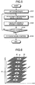
- FIG. 5 is a flowchart showing a calculation processing procedure for calculating the shape of the image axis.
- the fitting range setting unit 15a first sets a range where an intensity distribution model function is fitted to a pin-hole image as the aerial image (step S121).
- to fit means to apply.
- the intensity of the pin-hole image gradually decreases as the pin-hole image is farther from the maximum intensity position.
- the fitting range of the longitudinal direction (Z axis direction) is assumed to be the focal depth of the objective lens 7a.
- the fitting range of the lateral direction (X and Y axes directions) is assumed to be within 1/2 of the radius of an airy disk.
- the fitting range setting unit 15a retrieves a pixel with the maximum brightness from the image region where the pin-hole image is imaged on the stack image.
- a sampling point included within the cylindrical fitting range with the pixel position as the center is made a fitting target, which is described below.
- the fitting range may also be finely adjusted by increasing or reducing the values.
- the intensity distribution fitting unit 15b fits the intensity distribution model function I(x, y) (step S122).
- the leaf image means each observation image included in the stack image.
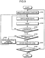
- FIG. 6 is a view showing the stack image in one pin-hole image.
- a cross section 22 of the pin-hole image is sampled (imaged) in each leaf image 23 for each Z axis position.
- the intensity distribution model function I(x, y) of the cross section 22 is fitted to the sampling point within the fitting range of one leaf image 23 by the least square method.
- the rotation-symmetrical two-dimensional Gaussian distribution function represented by the following equation (1), is adopted as the intensity distribution model function which can be easily fitted to the intensity distribution in the neighborhood of the maximum intensity position.
- I x y I max ⁇ exp ⁇ b 2 x ⁇ x c 2 + y ⁇ y c 2
- the intensity position calculation unit 15c calculates the maximum intensity position (x c , y c ) of one leaf image 23 from the fitting intensity distribution model function I(x, y) (step S123).
- the calculated maximum intensity position (x c , y c ) is also planar coordinates of the maximum value of the fitting intensity distribution model function I(x, y).
- the maximum intensity position (x c , y c ) of one leaf image can be obtained with higher accuracy than the sampling interval in the original X and Y axes directions.
- the sampling interval in the original X and Y axes directions is, for example, a sampling interval on the object side, which is determined by the pixel interval of the imaging device 10 and the lateral magnification of an optical system to be evaluated.
- the intensity position calculation unit 15c calculates the maximum intensity position (x c , y c ), alternatively a pixel with the maximum brightness value is retrieved from the sampling points within the fitting range of one leaf image, and the position of the brightness value is calculated.
- the control unit 18 determines whether the intensity distribution model function I(x, y) is fitted to all the leaf images included in the fitting range of the longitudinal direction, in other words, whether the number of the leaf images to which the intensity distribution model function I(x, y) is fitted has reached a predetermined fitting number (step S124).
- the control unit 18 proceeds to a step S125, while when the number has not reached the predetermined fitting number (S124: No), the processing from the step 122 is repeated.
- the maximum intensity position (x c , y c ) of each of the leaf images included in the fitting range of the longitudinal direction can be calculated.
- a position 24 of each leaf image 23 represents the maximum intensity position (x c , y c ) of each obtained leaf image.
- the curve fitting unit 15d fits a linear model function, which is a curve model function and represented by the following equations (2) and (3), to each component of the maximum intensity position (x c (z), y c (z)) of each leaf image as a function of Z axis coordinates by the least square method and calculates a straight line corresponding to the regression expression defining the image axis corresponding to the telecentricity (step S125).
- a linear model function which is a curve model function and represented by the following equations (2) and (3), to each component of the maximum intensity position (x c (z), y c (z)) of each leaf image as a function of Z axis coordinates by the least square method and calculates a straight line corresponding to the regression expression defining the image axis corresponding to the telecentricity (step S125).
- the inclination of the image axis by nontelecentricity can be approximated by the above straight line:
- x c z a x ⁇ z + b
- the curve fitting unit 15d fits a quadratic curve model function, which is a curve model function and represented by the following equations (4) and (5), to each component of the maximum intensity position (x c (z), y c (z)) of each leaf image by the least square method and calculates the quadratic curve corresponding to the regression expression defining the image axis corresponding to the coma aberration.
- the quadratic coefficients c x , c y of the respective quadratic curves represent the curvature of the image axis. When the coma aberration is small, the curvature of the image axis is approximately proportional to the coma aberration.
- the curve fitting unit 15d converts the inclination of the image axis a x and a y as the shape parameter of the image axis and the curvatures c x and c y which have been calculated as above described to the real coordinates on the object side or the image side, according to need.
- the sampling interval in the Z axis direction is converted into the step movement interval (unit: ⁇ m) of the Z axis stage 5.
- the sampling interval in the X and Y axes directions is converted into a value obtained by dividing the pixel interval (unit: ⁇ m) of the imaging device 10 by the lateral magnification of the microscope optical system 7. It is usually sufficient for this lateral magnification to be a design value of the microscope optical system 7. The same applies to the conversion to the real coordinates on the image side. Thereby, the calculation of one shape of the axis image is terminated.
- one shape of the image axis can be obtained with higher accuracy than the original sampling interval in the lens evaluation apparatus 100.
- the calculation processing procedure of the shape of the image axis shown in FIG. 5 has an advantage that such a complex transformation can be absorbed by the combination of relatively simple intensity distribution model functions.
- the control unit 18 determines whether the shape of the axis image is obtained in all the pin-hole images within the imaging range of the stack image of one wavelength, in other words, whether the number of the pin-hole images in which the shape of the image axis has been obtained, has reached the predetermined number (step S113).
- the control unit 18 proceeds to a step S114, while when the number has not reached the predetermined number (S113: No), the step 112 is repeated.
- S112 by repeating S112 until the step 113 is satisfied, all the shape of the image axis are calculated from all the pin-holes within the imaging range of the stack image with one wavelength.
- the control unit 18 determines whether the shape of the image axis corresponding to each pin-hole image is calculated for all of a plurality of wavelengths, in other words, whether the number of the wavelength in which the shape of the image axis of each pin-hole image is obtained has reached the predetermined number (step S114).
- the control unit 18 proceeds to a step S115, while when the number has not reached the predetermined number (S114: No), the processing from the step S111 is repeated.
- all the shapes of the image axis within the imaging range of each of the stack images with a plurality of wavelengths can be calculated. In other words, the distribution of the shape of the image axis of each wavelength can be calculated.
- control unit 18 makes the evaluation value calculation unit 16 calculate the evaluation equation showing each distribution of the telecentricity and the coma aberration, and accordingly calculates the evaluation value of the telecentricity and the coma aberration on the basis of the obtained evaluation equation (step S115).
- FIGS. 7A and 7B show an object side telecentric optical system as the optical system to be evaluated.
- a diaphragm 32 of an optical system 31 to be evaluated is disposed on a rear focal surface 35.
- FIG. 7A when a center position 33 of the diaphragm 32 is sifted from an optical axis 34 in the lateral direction (X and Y axes directions), a main beam 40 connecting the corresponding object point 38 and image point 39 is tilted to the optical axis 34 on the object side.
- the position of the image point 39 on the image surface 37 is not changed (however, this movement causes the blur of the image).
- the position of the image point 39 on the image surface 37 is shifted in the lateral direction.
- the shift in the lateral direction causes the inclination of the image axis.
- the relation between a lateral shift amount ⁇ and a vertical shift amount ⁇ of the center position 33 of the diaphragm 32 and inclination a on the object side of the main beam 40 is represented by the following equation (6) using the inclination a on the image side of the main beam 40, a position r of the object point 38, and focal length f of the optical system 31 to be evaluated.
- the inclination a and the position r are respectively represented by the following equations (7) and (8).
- the lateral shift amount ⁇ is represented by the following equation (9) using its X component ⁇ and Y component ⁇ .
- the inclination on the object side of the main beam 40 in other words, the inclination of the image axis a x and a y is represented by the primary expression in the X and Y axes directions.
- the linear model functions as characteristic distribution model functions represented by the following equations (10-1) and (10-2) are respectively fitted to the combination of the corresponding object point coordinates (x, y) and the inclination of the image axis ( a x , a y ) by the least square method, whereby the evaluation equation showing the distribution of the telecentricity can be obtained.
- a x Ax + B
- a y Ay + D
- the vertical shift amount ⁇ is preferably the average between the coefficients A and C for example.
- A ⁇ ⁇ / f 2
- D ⁇ / f
- the evaluation value calculation unit 16 calculates the evaluation value of the inclination of the image axis ( a x , a y ) corresponding to an arbitrary object coordinates (x, y) from the evaluation equation, obtained as above described, showing the distribution of the telecentricity.
- the evaluation value calculation unit 16 further can calculate the lateral shift amount ⁇ and the vertical shift amount ⁇ of the diaphragm of the objective lens 7a as the optical system to be evaluated by using the focal length f of the objective lens 7a.
- the distribution of the coma aberration is represented by the primary expression in the X and Y axes directions.
- the linear model functions as the characteristic distribution model functions represented by the following equations (12-1) and (12-2) are respectively fitted to the combination of the object point coordinates (x, y) and the curvature of the image axis (c x , c y ) by the least square method, whereby the evaluation equation showing the distribution of the coma aberration can be obtained.
- the evaluation value calculation unit 16 can obtain the evaluation value of the curvature of the image axis (c x , c y ) corresponding to the arbitrary object point coordinates (x, y) from the evaluation equation, obtained as above described, showing the distribution of the coma aberration.
- the evaluation value calculation unit 16 subtracts the shape of the image axis with the reference wavelength, obtained by the steps S111 to S114, from one shape of the image axis with the evaluation wavelength obtained by the steps S111 to S114. This calculation is applied to all the shapes of the image axis. Thereby, the evaluation value calculation unit 16 calculates the distributions of a difference of the inclination of the image axis ⁇ a x (x, y) and ⁇ a y (x, y) and the distributions of a difference of the curvature of the image axis ⁇ c x (x, y) and ⁇ c y (x, y) as the function of the object coordinates (x, y) (step S116).
- the distributions of the difference of the inclination of the image axis ⁇ a x (x, y) and ⁇ a y (x, y) and the distributions of the difference of the curvature of the image axis ⁇ c x (x, y) and ⁇ c y (x, y) are represented by the primary expression in the X and Y axes directions.
- the evaluation value calculation unit 16 fits the linear model function represented by the equations (10-1) and (10-2) to the combination of the corresponding object point coordinates (x, y) and the difference of the inclination of the image axis ( ⁇ a x , ⁇ a y ) by the least square method to obtain the evaluation equation of the difference of the telecentricity.
- the evaluation value calculation unit 16 fits the linear model function represented by the equations (12-1) and (12-2) to the combination of the corresponding object point coordinates (x, y) and the difference of the curvature of the image axis ( ⁇ c x , ⁇ c y ) by the least square method to obtain the evaluation equation of the difference of the coma aberration.
- the evaluation value calculation unit 16 can calculate the evaluation value of the difference of the inclination of the image axis and the evaluation value of the difference of the curvature of the image axis respectively corresponding to the arbitrary object point coordinates (x, y).
- a drift component such as a sample position progressing in the imaging time of the stack image is measured as the shape of the image axis.
- this drift component is eliminated by averaging the above-mentioned difference, whereby only the wavelength dependence of the telecentricity and the coma aberration is evaluated.
- the evaluation equation of each difference of the telecentricity and the coma aberration may be calculated by the difference of each evaluation equation of the telecentricity and the coma aberration calculated by the step S115.
- the control unit 18 determines whether the steps S115 and S116 are applied to all the plurality of wavelengths, in other words, whether the number of the wavelength used for the calculation of the evaluation equation has reached the predetermined number (step S117).
- the control unit 18 terminates the analysis processing, while when the number has not reached the predetermined number (S117: No), the processing from the step S115 is repeated.
- the steps S115 and S116 are repeated until the S117 is satisfied, whereby the respective evaluation equations of the telecentricity and the coma aberration with respect to the plurality of wavelengths can be calculated.
- Each shape of the image axis has measurement errors due to the error in the amount of movement of the Z axis stage 5, the error of imaging position calculation, and the like.
- the measurement errors of each shape of the image axis are balanced out by each other, whereby the respective evaluation equations of the telecentricity and the coma aberration can be obtained with high accuracy.
- the lens evaluation apparatus 100 in order to evaluate the distribution of the telecentricity and the distribution of the coma aberration in a single objective lens 7a, it is effective to add the following procedure.
- a component attributable to the objective lens 7a is rotated and moved upon the rotation of the objective lens 7a.
- the operation is described below with reference to FIG. 8 .
- the movement of the X and Y coordinates accompanying the rotation of the objective lens 7a draws the locus of a circle 45.
- the center 46 of the circle 45 does not always coincide with the center 47 of the view field.
- the difference 48 between both is a component attributable to the errors in the disposition of the optical system other than the objective lens 7a and devices.
- the radius 49 of the circle 45 is a component attributable to the objective lens 7a.
- steps S107 and S109 are added in a flowchart shown in FIG. 3 , whereby the stack images while the objective lens 7a is rotated is obtained.
- the objective lens 7a is rotated by 180° by the rotation part 8, and the same measurement is then performed.
- the average of the parameters of the X and Y coordinates of both is a component attributable to other than the objective lens 7a. 1/2 of the difference between both is a component attributable to the objective lens 7a.
- the rotation angle is divided, and the measurement is performed, for example, the center 46 and radius 49 of the circle 45 are calculated at four rotation positions of 0°, 90°, 180° and 270°, both components can be separated with further higher accuracy.
- the other parameters (vertical shift amount of a diaphragm), included in the respective evaluation equations of the distribution of the telecentricity and the distribution of the coma aberration never change accompanying the rotation of the objective lens 7a.
- the measurement errors of these values can be improved by averaging the plurality of measurement values.
- the drift of the positions of the sample 4 and the like progressing in the imaging time is also measured as the shape of the image axis.
- a measure using the following reciprocating measurement is effective.
- the shape of the image axis is calculated from the respective stack images of the forward path and the backward path.
- the shape of the image axis attributable to the telecentricity and the coma aberration is common to the forward path and the backward path, the inclination caused by the linear drift is inverted.
- the telecentricity and coma aberration and the drift components can be separated by taking the sum of both or the difference.
- the calculation of the shape of the image axis according to such a reciprocating change of the relative distance is performed one or more times, especially a plurality of times, whereby the error of the evaluation value can be further reduced.
- the lens evaluation apparatus 100 as the optical system evaluation apparatus according to the first embodiment has a plurality of pin-holes 4a as the point light sources arranged in a planar form, and is provided with the sample 4, which is a point image production means for forming, for each pin-hole 4a, a pin-hole image as the point image through the optical system to be evaluated, the light source 1, the optical fiber 2, the light intensity uniformization part 3, the image forming lens 7b, the imaging device 10, which images the plurality of pin-hole images to produce the observation image as the point image distribution image, the Z axis stage 5 as the movement means for changing the relative distance between the optical system to be evaluated and the sample 4 in the optical axis direction of the optical system to be evaluated, the control unit 18 which makes the Z axis stage 5 change the relative distance and makes the imaging device 10 image the observation image in every change of the relative distance, the image axis shape calculation unit 15 which, on the basis of the image information of the stack images which are formed from the plurality of the observation images formed at a different
- the evaluation value calculation unit 16 especially, fits the model function as the characteristic distribution model function representing at least one distribution of the telecentricity and the coma aberration to calculate the evaluation equation showing at lease one distribution of the telecentricity and the coma aberration as the distribution of the optical characteristics of the optical system to be evaluated, and, thus, to calculate the evaluation value on the basis of this evaluation equation.
- the lens evaluation apparatus 100 can evaluate the distribution of the optical characteristics of the optical system to be evaluated in a short time with high accuracy. Specifically, even when one pin-hole image cannot be imaged with particularly large number of pixels, the evaluation can be performed with high accuracy. In addition, in the lens evaluation apparatus 100, a laser length measuring machine with nm-order accuracy for monitoring the image forming position of the pin-hole image and the like is not required, whereby the high precision evaluation can be realized by simple and inexpensive configuration.
- the sample 4 is moved on the Z axis stage 5 in the optical direction, and the telecentricity on the object side is then evaluated; however, alternatively the imaging device 10 is moved in the optical axis direction, and the similar imaging processing and analysis processing are then performed, whereby the telecentricity on the image side can be evaluated.
- the imaging device 10 is moved in the optical axis direction, and the similar imaging processing and analysis processing are then performed, whereby the telecentricity on the image side can be evaluated.
- the interval of the step movement amount is not required to be constant.
- the sample 4 trans-illuminated by the light source 1 may have another form.
- it may be an incident end of an optical fiber, an illuminant like a fluorescent bead, or the like which are arranged in a planar form.
- the pin-hole array specimen as shown in FIG. 2 is assumed to "negative", its "positive” specimen can also be used. Specifically, a specimen in which only the parts of the metal film 4b corresponding to the pin-holes 4a in FIG. 2 are left and the other parts of metal film 4b are removed can be used.
- each metal film 4b can be regarded to be a plurality of point light sources when such a specimen is epi-illuminated.
- an illuminant with a single wavelength such as a light-emitting diode array can also be used. It is desirable for the size of this point light source to be equal to or less than the resolution of the optical system to be evaluated.
- FIG. 10 shows a relevant configuration of a fluorescent confocal microscope 200 as the optical system evaluation apparatus according to the second embodiment.
- the fluorescent confocal microscope 200 is provided with a laser light source 51, a dichroic mirror 53, an XY scanner 54, a total reflection mirror 55, an objective lens system 56, a sample 57, a Z axis stage 58, a confocal optical system 59, a light detection system 60, a control unit 61, a computer 62, and a display unit 63.
- the illumination light (excitation light) from the laser light source 51 for selectively emitting laser beams with a plurality of wavelengths is collected to the focal position of the sample 57 by the objective lens system 56 via the XY scanner 54 and the total reflection mirror 55.
- the reflection light (fluorescent) from the sample 57 is branched and reflected by the dichroic mirror 53, which is provided between the XY scanner 54 and the laser light source 51, via the objective lens system 56 and the total reflector 55 and is then received by the light detection system 60 via the confocal optical system 59.
- only reflection light from the focal position on the sample 57 is incident on the light detection system 60 by the confocal effect of the confocal optical system 59.
- the incident light is photoelectrically converted by the light detection system 60 to be transmitted to the computer 62 as brightness information.
- the XY scanner 54 is constituted by using an X galvano-mirror for swinging the luminous flux of the illumination light from the laser light source 51 to the X axis direction and a Y galvano-mirror for swinging the luminous flux to the Y axis direction perpendicular to the X axis direction, and can scan the light converging position in the sample 57 in the X and Y axes directions that are perpendicular to each other against the optical axis of the objective lens system 56.
- the Z axis stage 58 moves the sample 57 in the Z axis direction as the optical axis direction with holding the sample 57 placed thereon.
- the Z axis stage 58 moves the sample 57 in the optical axis direction and therefore can move the focal position of the sample 57 in the optical axis direction.
- the computer 62 builds up the scan image of the sample 57 on the basis of the brightness information output from the light detection system 60 in accordance with the scanning through the sample 57 of the illumination light by the XY scanner 54.
- the built scan image can be viewed by displaying it on the display unit 63.
- the computer 62 is provided with an image axis shape calculation unit, an evaluation value calculation unit, a storage unit, and a control unit (not shown) as with the control device 14 according to the first embodiment.
- the control unit 61 controls the laser light source 51, the XY scanner 54, the Z axis stage 58, and the like, which are connected to each other, on the basis of instructions of the computer 62.
- the sample 57 is a specimen having a plurality of reflective pin-holes formed therein in which only the parts of the metal film 4b corresponding to the pin-holes 4a shown in FIG. 2 are left and the other parts of the metal film 4b are removed.
- the metal film 4b is removed from the region other than the reflective pin-holes.
- the operator focuses a stack image by the Z axis stage 58 while monitoring the observation image obtained by the scanning of the XY scanner 54 on a display unit 63. Then, the CPU of the computer 62 starts executing an imaging program.
- This imaging program is a part of a control program recorded in the storage unit of the computer 62 and automatically controls to image the stack image with a plurality of wavelengths.
- the imaging processing procedure by this imaging program is described below with reference to FIG. 3 .
- the plurality of wavelengths can be alternatively oscillated from the laser light source 51 in accordance with the control from the control unit 61.
- the control unit 61 first moves the Z axis stage 58 from the focus position (position after the focusing) to the bottom of the imaging range (step S101). It is desirable to set the imaging range in the Z axis direction to approximately several times of focal depth in such a way as to include the field curvature and the chromatic aberration range in the longitudinal direction of the objective lens system 56 as the optical system to be evaluated.
- control unit 61 switches the wavelength of the laser light source 51, whereby switching the wavelength of the illumination light to one wavelength in which the observation image is not imaged yet in the current Z axis stage position, among the plurality of wavelengths (step S102).
- control unit 61 images the observation image of the sample 57 by the scanning of the XY scanner 54 to record the observation image in the storage unit of the computer 62 (step S103).
- the control unit 61 determines whether steps S112 and S113 are applied to all the plurality of wavelengths in the current Z axis stage position, in other words, whether the number of the wavelengths used for the imaging has reached the predetermined number (step S104).
- the control unit 61 proceeds to a step S105, while when the number has not reached the predetermined number (S104: No), the processing from S102 is repeated.
- the image files of the observation images of each of the plurality of wavelengths in the current Z axis stage position are stored in the storage unit of the computer 62.
- the control unit 61 determines whether the number of the image files of each wavelength stored in the storage unit of the computer 62 has reached the number of stack images covering a predetermined imaging range in the Z direction (Step S105).
- the control unit 61 terminates the imaging processing, while when the number has not reached the number of the stack images (S105: No), the Z axis stage 58 is moved upward by one step (step S106), and thereafter the processing from S102 is repeated.
- the movement amount of one step is desirably about 1/5 to 1/10 of the focal depth of the objective lens system 56 to be evaluated.
- the image files of each wavelength for the number of stack images covering the predetermined imaging range in the Z axis direction are stored as the stack images in the storage unit of the computer 62.
- the shape of the image axis corresponding to each pin-hole image is obtained by the analysis processing as in the lens evaluation apparatus 100, and, at the same time, the evaluation value of the distribution of the telecentricity and the distribution of the coma aberration as the distribution of the optical characteristics of the objective lens system 56 is calculated on the basis of the shape of the image axis. Accordingly, in the fluorescent confocal microscope 200, as with the lens evaluation apparatus 100, the distribution of the optical characteristics of the objective lens system 56 can be evaluated in a short time with high accuracy.
- the fluorescent confocal microscope 200 scans through the sample 57 by one light converging point
- the present invention is also applicable to a confocal microscope which uses a Nipknow disk or the like and scans through a sample by a plurality of light converging points.
- the excitation light and the fluorescent light are somewhat different in the fluorescent confocal microscope 200.
- the evaluation is performed by only excitation light wavelengths; however, when a plurality of fluorescent bead samples arranged in a planar form is adopted as the sample 57 with a point light source array, it is possible to realize more accurate evaluation including a wavelength difference between the excitation light and the fluorescent light.
- a point light source array may be formed by the trans-illumination, using a pin-hole array specimen.
- an arbitrary evaluation wavelength can be set to be different from a laser light source, the shape of the image axis and the distribution of the optical characteristics can be evaluated by a fluorescent light wavelength or the intermediate wavelength between the excitation light and the fluorescent light.
- the optical system evaluation apparatus can also be applied to optical systems other than a microscope.
- the optical system other than a microscope there are various image-forming optical systems including a reflection system, a catadioptric system, or the like, in addition to a lens system (refracting system).
- a lens system refracting system
- appropriate point light sources are required.
- This also applies to the step movement amount and movement range of a movement mechanism for imaging a stack image. The requirements necessary in that case is already clear from the above description.
- the processing procedure for calculating the evaluation equations of the respective distributions of the telecentricity and the coma aberration from the stack image the same one as in the microscopic optical system can be applied.
Landscapes
- Physics & Mathematics (AREA)
- Chemical & Material Sciences (AREA)
- Analytical Chemistry (AREA)
- General Physics & Mathematics (AREA)
- Geometry (AREA)
- Length Measuring Devices By Optical Means (AREA)
- Testing Of Optical Devices Or Fibers (AREA)
Claims (37)
- Vorrichtung (100), die dafür ausgelegt ist, optische Eigenschaften eines optischen Systems (7) basierend auf einer Bilderzeugungsposition eines Punktbildes zu bewerten, das anhand einer Punktlichtquelle (4a) durch das optische System (7) gebildet wird, wobei die Vorrichtung (100) umfasst:- eine Punktbilderzeugungseinrichtung (1 bis 4; 4b), die eine Mehrzahl Punktlichtquellen (4a) aufweist, welche in der Nähe einer Objektoberfläche des optischen Systems (7) positioniert und planar angeordnet sind, und die dafür ausgelegt ist, eine Mehrzahl der Punktbilder durch das optische System (7) anhand der Punktlichtquellen (4a) zu erzeugen,- eine Abbildungseinrichtung (10), die dafür ausgelegt ist, eine Mehrzahl der Punktbilder abzubilden, um ein Punktbildverteilungsbild zu erzeugen,- eine Bewegungseinrichtung (5, 12), die dafür ausgelegt ist, einen relativen Abstand (i) zwischen der Punktlichtquelle (4a) und dem optischen System (7) oder (ii) zwischen dem optischen System (7) und der Abbildungseinrichtung (10) in Richtung der optischen Achse (9) des optischen Systems (7) zu ändern,- eine Abbildungssteuereinrichtung (18), die dafür ausgelegt ist, die Bewegungseinrichtung (5) zu steuern, um den relativen Abstand (i) zwischen der Punktlichtquelle (4a) und dem optischen System (7) oder (ii) zwischen dem optischen System (7) und der Abbildungseinrichtung (10) zu ändern, und die Abbildungseinrichtung (10) zu steuern, um das Punktbildverteilungsbild bei jeder Änderung des relativen Abstands (i) zwischen der Punktlichtquelle (4a) und dem optischen System (7) oder (ii) zwischen dem optischen System (7) und der Abbildungseinrichtung (10) abzubilden,- eine Bildachsenformberechnungseinrichtung (15), die dafür ausgelegt ist, bei jedem unterschiedlichen relativen Abstand des Punktbilds basierend auf Bildinformationen einer Mehrzahl der unter dem unterschiedlichen relativen Abstand abgebildeten Punktbildverteilungsbilder eine Verarbeitung einer Erfassung einer Bilderzeugungsposition durchzuführen,- dadurch gekennzeichnet, dass die Verarbeitung das Berechnen eines die Bilderzeugungsposition und den relativen Abstand betreffenden Regressionsausdrucks für jedes der Punktbilder umfasst, um einen Formparameter der Bildachse zu erhalten, der bei jedem der Mehrzahl Punktbilder durch den Regressionsausdruck bestimmt wird, und- eine Bewertungswertberechnungseinrichtung (16), die dafür ausgelegt ist, bei jedem der Mehrzahl Punktbilder eine Eigenschaftsverteilungsmodellfunktion, die eine Verteilung der optischen Eigenschaften repräsentiert, an den Formparameter anzupassen und einen Bewertungswert der optischen Eigenschaften basierend auf der passenden Eigenschaftsverteilungsmodelfunktion zu berechnen.
- Vorrichtung (100) nach Anspruch 1, wobei die Eigenschaftsverteilungsmodelfunktion eine Verteilung der Telezentrizität und/oder Koma-Aberration repräsentiert.
- Vorrichtung (100) nach Anspruch 1, wobei die Bildachsenformberechnungseinrichtung (15) umfasst:- eine Intensitätsverteilungsanpassungseinrichtung (15b), die dafür ausgelegt ist, bei jedem der unter dem unterschiedlichen relativen Abstand abgebildeten Punktverteilungsbilder eine Intensitätsverteilungsmodellfunktion, die eine zweidimensionale Intensitätsverteilung eines Punktbildbereichs repräsentiert, in dem das Punktbild abgebildet wird, an den Punktbildbereich anzupassen,- eine Intensitätspositionsberechnungseinrichtung (15c), die dafür ausgelegt ist, bei jedem der unter dem unterschiedlichen relativen Abstand abgebildeten Punktbildverteilungsbilder auf dem Punktbildverteilungsbild mit der durch die Intensitätsverteilungsanpassungseinrichtung (15b) angepassten Maximalintensitätsverteilungsmodellfunktion eine planare Koordinate zu erfassen und die Maximalintensitätsposition des Punktbildes bei dem relativen Abstand, bei dem das Punktbildverteilungsbild abgebildet wird, unter Verwendung der erfassten planaren Koordinate als Bilderzeugungsposition des Punktbilds zu berechnen, und- eine Kurvenanpassungseinrichtung (15d), die dafür ausgelegt ist, bei jedem unterschiedlichen relativen Abstand eine Kurvenmodellfunktion als Regressionsausdruck an eine Mehrzahl Maximalintensitätspositionen anzupassen und einen Koeffizienten der passenden Kurvenmodellfunktion als Formparameter zu erhalten.
- Vorrichtung (100) nach Anspruch 3, wobei- die Bildachsenformberechnungseinrichtung (15) eine Bereichseinstelleinrichtung umfasst, die dafür ausgelegt ist, einen passenden Bereich der Intensitätsverteilungsmodelfunktion für das Punktbild einzustellen, und- die Intensitätsverteilungsanpassungseinrichtung (15b) dafür ausgelegt ist, bei jedem der unter dem unterschiedlichen relativen Abstand abgebildeten Punktverteilungsbilder innerhalb des passenden Bereichs die Intensitätsverteilungsmodellfunktion an den Punktbildbereich anzupassen.
- Vorrichtung (100) nach Anspruch 3, wobei die Intensitätsverteilungsmodellfunktion eine zweidimensionale Gaußsche Verteilungsfunktion ist.
- Vorrichtung (100) nach Anspruch 1, wobei die Bildachsenformberechnungseinrichtung (15) umfasst:- eine Intensitätspositionsberechnungseinrichtung (15c), die dafür ausgelegt ist, bei jedem der unter dem unterschiedlichen relativen Abstand abgebildeten Bildverteilungsbilder eine Pixelposition zu erfassen, die die maximale Helligkeit in dem Punktbildbereich repräsentiert, in dem das Punktbild abgebildet wird, und die Maximalintensitätsposition des Punktbildes bei dem relativen Abstand, bei dem das Punktbildverteilungsbild abgebildet wird, basierend auf der erfassten Pixelposition als Bilderzeugungsposition des Punktbildes zu berechnen, und- eine Kurvenanpassungseinrichtung (15d), die dafür ausgelegt ist, bei jedem unterschiedlichen relativen Abstand eine Kurvenmodellfunktion als Regressionsausdruck an eine Mehrzahl der Maximalintensitätspositionen anzupassen und einen Koeffizienten der passenden Kurvenmodellfunktion als Formparameter zu erhalten.
- Vorrichtung (100) nach Anspruch 6, wobei- die Bildachsenformberechnungseinrichtung (15) eine Bereichseinstelleinrichtung umfasst, die dafür ausgelegt ist, einen Abrufbereich der Pixelposition für das Punktbild einzustellen, und- die Intensitätspositionsberechnungseinrichtung (15c) dafür ausgelegt ist, bei jedem der unter dem unterschiedlichen relativen Abstand abgebildeten Punktbildverteilungsbilder innerhalb des Abfragebereichs die Pixelposition zu erfassen.
- Vorrichtung (100) nach einem der Ansprüche 3 bis 7, wobei die Kurvenmodellfunktion eine lineare Modellfunktion ist, die eine gerade Linie repräsentiert.
- Vorrichtung (100) nach einem der Ansprüche 3 bis 7, wobei die Kurvenmodellfunktion eine quadratische Kurvenmodellfunktion ist, die eine quadratische Kurve repräsentiert.
- Vorrichtung (100) nach einem der Ansprüche 1 bis 7, wobei- die Punktbilderzeugungseinrichtung dafür ausgelegt ist, die Punktlichtquelle zu veranlassen, Licht in einer Mehrzahl Wellenlängenbereiche umschaltbar zu emittieren und das Punktbild in jedem Licht der Mehrzahl Wellenlängenbereiche zu bilden,- die Abbildungssteuereinrichtung (18) dafür ausgelegt ist, die Punktbilderzeugungseinrichtung zu steuern, um bei jeder Änderung des relativen Abstands durch die Bewegungseinrichtung (5) das Punktbild sequentiell mit Licht der Mehrzahl Wellenlängenbereiche zu bilden, und die Abbildungseinrichtung (10) zu steuern, um das Punktbildverteilungsbild in jedem Licht der Mehrzahl Wellenlängenbereiche zu abzubilden,- die Bildachsenformberechnungseinrichtung (15) dafür ausgelegt ist, bei jedem der Mehrzahl Punktbilder in jedem Licht der Mehrzahl Wellenlängenbereiche eine Verarbeitung zum Erhalten des Formparameters durchzuführen und einen Differenzparameter, der eine Differenz zwischen den jeweiligen Formparametern im Licht eines ersten Wellenlängenbereichs und im Licht eines zweiten Wellenlängenbereichs repräsentiert, in Bezug auf das Licht der Mehrzahl Wellenlängenbereiche zu berechnen, und- die Bewertungswertberechnungseinrichtung (16) dafür ausgelegt ist, bei jedem der Mehrzahl Punktbilder eine Differenzverteilungsmodellfunktion, die die Verteilung der Differenz der jeweiligen optischen Eigenschaften im Licht des ersten Wellenlängenbereichs und im Licht des zweiten Wellenlängenbereichs repräsentiert, an jeden der Differenzparameter anzupassen und den Bewertungswert der Differenz der optischen Eigenschaften basierend auf der passenden Differenzverteilungsmodellfunktion zu berechnen.
- Vorrichtung (100) nach einem der Ansprüche 1 bis 7, die ferner umfasst:- eine Dreheinrichtung, die dafür ausgelegt ist, ein optisches Teilsystem, das wenigstens einen Teil des optischen Systems (7) umfasst, um eine optische Achse des optischen Teilsystems zu drehen,- wobei die Bewertungswertberechnungseinrichtung (16) dafür ausgelegt ist, für durch die Dreheinrichtung bewirkte Differenzdrehpositionen des optischen Teilsystems einen Bewertungswert der optischen Eigenschaften zu berechnen und basierend auf der Mehrzahl der berechneten Bewertungswerte der optischen Eigenschaften die Bewertungswerte der optischen Eigenschaften in eine dem optischen Teilsystem entsprechende Komponente und eine nicht dem optischen Teilsystem entsprechende Komponente aufzuteilen.
- Vorrichtung (100) nach einem der Ansprüche 1 bis 7, wobei- die Abbildungssteuereinrichtung (18) dafür ausgelegt ist, die Bewegungseinrichtung (5) zu steuern, um wenigstens einmal eine Hin- und Heränderung durchzuführen, bei der der relative Abstand innerhalb eines vorgegebenen Bereichs erhöht oder verringert wird, und die Abbildungseinrichtung (10) zu steuern, um das Punktbildverteilungsbild bei jeder Änderung des relativen Abstands während des Erhöhens und Verringerns des relativen Abstands abzubilden,- die Bildachsenformberechnungseinrichtung (15) dafür ausgelegt ist, bei jedem der Mehrzahl Punktbilder basierend auf Bildinformationen einer Mehrzahl der während des Erhöhens und Verringerns des relativen Abstands abgebildeten Punktbildverteilungsbilder die Formparameter zu erhalten, die jeweils dem erhöhten relativen Abstand und dem verringerten relativen Abstand entsprechen, und- die Bewertungswertberechnungseinrichtung (16) dafür ausgelegt ist, basierend auf dem Formparameter, der jeweils dem erhöhten relativen Abstand und dem verringerten relativen Abstand entspricht, den Bewertungswert der optischen Eigenschaften zu berechnen, der jeweils dem erhöhten relativen Abstand und dem verringerten relativen Abstand entspricht, und basierend auf der Mehrzahl berechneter Bewertungswerte der optischen Eigenschaften den Bewertungswert der optischen Eigenschaften in eine dem optischen System (7) entsprechende Komponente und eine nicht dem optischen System (7) entsprechende Komponente aufzuteilen.
- Vorrichtung (100) nach einem der Ansprüche 1 bis 7, wobei das optische System (7) eine Membran (32) umfasst, die Eigenschaftsverteilungsmodellfunktion die Verteilung der Telezentrizität repräsentiert und die Bewertungswertberechnungseinrichtung (16) dafür ausgelegt ist, basierend auf der Eigenschaftsverteilungsmodellfunktion einen Seitenverschiebungsbetrag der Membran und/oder ihren Vertikalverschiebungsbetrag zu berechnen.
- Vorrichtung (100) nach einem der Ansprüche 1 bis 7, wobei die Punktbilderzeugungseinrichtung umfasst:- eine Mehrzahl Stiftlöcher, die jeweils einen Durchmesser aufweisen, der gleich oder kleiner als die Auflösung des optischen Systems (7) ist, und planar angeordnet sind, und- eine Beleuchtungseinrichtung (1, 2, 3), die dafür ausgelegt ist, die Mehrzahl Stiftlöcher zu durchstrahlen, und- wobei die durch die Beleuchtungseinrichtung (1, 2, 3) angestrahlte Mehrzahl Stiftlöcher als Mehrzahl Punktlichtquellen (4a) verwendet wird.
- Vorrichtung (100) nach einem der Ansprüche 1 bis 7, wobei die Punktbilderzeugungseinrichtung umfasst:- eine Mehrzahl mikroreflektierender Spiegel (57), die jeweils einen Durchmesser aufweisen, der gleich oder kleiner als die Auflösung des optischen Systems (7) ist, und planar angeordnet sind, und eine Beleuchtungseinrichtung (1, 2, 3), die dafür ausgelegt ist, die Mehrzahl mikroreflektierender Spiegel (57) mit Auflicht zu anzustrahlen, und- wobei die durch die Beleuchtungseinrichtung (1, 2, 3) angestrahlte Mehrzahl mikroreflektierender Spiegel (57) dafür ausgelegt ist, als die Mehrzahl Punktlichtquellen (4a) verwendet zu werden.
- Vorrichtung (100) nach einem der Ansprüche 1 bis 7, wobei die Abbildungseinrichtung (10) eine zweidimensionale Abbildungseinrichtung umfasst, die dafür ausgelegt ist, die Mehrzahl Punktbilder abzubilden.
- Vorrichtung (100) nach einem der Ansprüche 1 bis 7, wobei die Punktbilderzeugungseinrichtung ein konfokales optisches System (59) umfasst, das konjugiert mit der Mehrzahl Punktlichtquellen (4a) im optischen System (7) bereitgestellt und dafür ausgelegt ist, durch das konfokale optische System (59) bei jeder der Punktlichtquellen (4a) am Punktbild eine konfokale Detektion durchzuführen.
- Vorrichtung (100) nach einem der Ansprüche 1 bis 7, wobei die Abbildungssteuereinrichtung (18) dafür ausgelegt ist, die Punktbilderzeugungseinrichtung zu steuern, um von der Mehrzahl Punktlichtquellen (4a) sequentiell Licht zu emittieren, um bei jeder Bewegung des relativen Abstands durch die Bewegungseinrichtung (5) sequentiell die Mehrzahl Punktbilder zu bilden, und die Abbildungseinrichtung (10) zu steuern, um die sequentiell gebildeten Punktbilder sequentiell abzubilden, um das Punktbildverteilungsbild zu erzeugen.
- Vorrichtung (100) nach einem der Ansprüche 1 bis 7, wobei das optische System (7) ein telezentrisches optisches System ist.
- Vorrichtung (100) nach Anspruch 19, wobei die Bewegungseinrichtung (5) den relativen Abstand auf einer telezentrischen Seite des optischen Systems (7) ändert.
- Vorrichtung (100) nach einem der Ansprüche 1 bis 7, wobei das optische System (7) ein für ein Mikroskop verwendetes mikroskopisches optisches System ist.
- Vorrichtung (100) nach Anspruch 21, wobei wenigstens ein Teil des optischen Systems (7) eine Objektivlinse ist.
- Verfahren zum Bewerten von optischen Eigenschaften eines optischen Systems (7) basierend auf einer Bilderzeugungsposition eines Punktbildes, das anhand einer Punktlichtquelle durch das optische System (7) gebildet wird, wobei das Verfahren umfasst:- Bilden eines Punktbildes durch das optische System (7) in jeder einer Mehrzahl Punktlichtquellen (4a), die in der Nähe einer Objektoberfläche des optischen Systems (7) positioniert und planar angeordnet sind,- Abbilden einer Mehrzahl der Punktbilder durch eine Abbildungseinrichtung (10), um ein Punktbildverteilungsbild zu erzeugen,- Ändern eines relativen Abstands(i) zwischen der Punktlichtquelle (4a) und dem optischen System (7) oder(ii) zwischen dem optischen System (7) und der Abbildungseinrichtung (10) in Richtung der optischen Achse (9) des optischen Systems (7),- Steuern der Abbildungseinrichtung (10), um das Punktbildverteilungsbild bei jeder Änderung des relativen Abstands (i) zwischen der Punktlichtquelle (4a) und dem optischen System (7) oder (ii) zwischen dem optischen System (7) und der Abbildungseinrichtung (10) abzubilden,- Durchführen, bei jedem der Mehrzahl Punktbilder, einer Verarbeitung zur Erfassung einer Bilderzeugungsposition bei jedem unterschiedlichen relativen Abstand des Punktbilds basierend auf Bildinformationen einer Mehrzahl der unter dem unterschiedlichen relativen Abstand abgebildeten Punktbildverteilungsbilder,- dadurch gekennzeichnet, dass die Verarbeitung das Berechnen eines die Bilderzeugungsposition und den relativen Abstand betreffenden Regressionsausdrucks für jedes der Punktbilder umfasst, um einen Formparameter der Bildachse zu erhalten, der bei jedem der Mehrzahl Punktbilder durch den Regressionsausdruck bestimmt wird,- Anpassen einer Eigenschaftsverteilungsmodellfunktion, die eine Verteilung der optischen Eigenschaften repräsentiert, an den Formparameter, und- Berechnen eines Bewertungswerts der optischen Eigenschaften basierend auf der passenden Eigenschaftsverteilungsmodelfunktion.
- Verfahren nach Anspruch 23, wobei die Eigenschaftsverteilungsmodelfunktion eine Verteilung der Telezentrizität und/oder Koma-Aberration repräsentiert.
- Verfahren nach Anspruch 23, wobei die Verarbeitung umfasst:- Anpassen einer Intensitätsverteilungsmodellfunktion, die eine zweidimensionale Intensitätsverteilung eines Punktbildbereichs repräsentiert, in dem das Punktbild abgebildet wird, an den Punktbildbereich bei jedem der unter dem unterschiedlichen relativen Abstand abgebildeten Punktverteilungsbilder,- Erfassen einer planaren Koordinate auf dem Punktbildverteilungsbild mit der durch die Intensitätsverteilungsanpassungseinrichtung (15b) angepassten Maximalintensitätsverteilungsmodellfunktion bei jedem der unter dem unterschiedlichen relativen Abstand abgebildeten Punktbildverteilungsbilder,- Berechnen der Maximalintensitätsposition des Punktbildes bei dem relativen Abstand, bei dem das Punktbildverteilungsbild abgebildet wird, als Bilderzeugungsposition des Punktbilds unter Verwendung der erfassten planaren Koordinate, und- Anpassen einer Kurvenmodellfunktion als Regressionsausdruck an eine Mehrzahl der Maximalintensitätspositionen bei jedem unterschiedlichen relativen Abstand, um einen Koeffizienten der passenden Kurvenmodellfunktion als Formparameter zu erhalten.
- Verfahren nach Anspruch 25, wobei die Verarbeitung das Einstellen eines passenden Bereichs der Intensitätsverteilungsmodelfunktion für das Punktbild umfasst und das Anpassen der Intensitätsverteilungsmodellfunktion das Anpassen der Intensitätsverteilungsmodellfunktion an den Punktbildbereich innerhalb des passenden Bereichs bei jedem der unter dem unterschiedlichen relativen Abstand abgebildeten Punktverteilungsbilder umfasst.
- Verfahren nach Anspruch 25, wobei die Intensitätsverteilungsmodellfunktion eine zweidimensionale Gaußsche Verteilungsfunktion ist.
- Verfahren nach Anspruch 23, wobei die Verarbeitung umfasst:- Erfassen einer Pixelposition, die die maximale Helligkeit in dem Punktbildbereich repräsentiert, in dem das Punktbild abgebildet wird, bei jedem der unter dem unterschiedlichen relativen Abstand abgebildeten Bildverteilungsbilder,- Berechnen, als Bilderzeugungsposition des Punktbildes, der Maximalintensitätsposition des Punktbildes bei dem relativen Abstand, bei dem das Punktbildverteilungsbild abgebildet wird, basierend auf der erfassten Pixelposition und- Anpassen einer Kurvenmodellfunktion als Regressionsausdruck an eine Mehrzahl der Maximalintensitätspositionen bei jedem unterschiedlichen relativen Abstand, um einen Koeffizienten der passenden Kurvenmodellfunktion als Formparameter zu erhalten.
- Verfahren nach Anspruch 28, wobei- die Verarbeitung das Einstellen eines Abrufbereichs der Pixelposition für das Punktbild umfasst, und- das Berechnen der Maximalintensitätsposition das Erfassen der Pixelposition innerhalb des Abfragebereichs bei jedem der unter dem unterschiedlichen relativen Abstand abgebildeten Punktbildverteilungsbilder umfasst.
- Verfahren nach einem der Ansprüche 25 bis 29, wobei die Kurvenmodellfunktion eine lineare Modellfunktion ist, die eine gerade Linie repräsentiert.
- Verfahren nach einem der Ansprüche 25 bis 29, wobei die Kurvenmodellfunktion eine quadratische Kurvenmodellfunktion ist, die eine quadratische Kurve repräsentiert.
- Verfahren nach einem der Ansprüche 23 bis 29, wobei- das Bilden das Veranlassen der Punktlichtquelle, Licht in einer Mehrzahl Wellenlängenbereiche umschaltbar zu emittieren, und das Bilden des Punktbilds in jedem Licht der Mehrzahl Wellenlängenbereiche umfasst,- das Steuern der Abbildungseinrichtung (10) umfasst, dass die Abbildungssteuereinrichtung (18) die Punktbilderzeugungseinrichtung steuert, um bei jeder Änderung des relativen Abstands aufgrund der Änderung das Punktbild sequentiell mit Licht der Mehrzahl Wellenlängenbereiche zu bilden, und die Abbildungseinrichtung (10) steuert, um das Punktbildverteilungsbild in jedem Licht der Mehrzahl Wellenlängenbereiche zu abzubilden,- die Verarbeitung in jedem Licht der Mehrzahl Wellenlängenbereiche durchgeführt wird und ein Differenzparameter berechnet wird, der eine Differenz zwischen den jeweiligen Formparametern im Licht eines ersten Wellenlängenbereichs und im Licht eines zweiten Wellenlängenbereichs repräsentiert, und- das Berechnen des Bewertungswerts das Anpassen einer Differenzverteilungsmodellfunktion, die die Verteilung der Differenz der jeweiligen optischen Eigenschaften im Licht des ersten Wellenlängenbereichs und im Licht des zweiten Wellenlängenbereichs repräsentiert, an jeden der Differenzparameter bei jedem der Mehrzahl Punktbilder und das Berechnen des Bewertungswerts der Differenz der optischen Eigenschaften basierend auf der passenden Differenzverteilungsmodellfunktion umfasst.
- Verfahren nach einem der Ansprüche 23 bis 29, das ferner umfasst:- Drehen eines optischen Teilsystems, das wenigstens einen Teil des optischen Systems (7) umfasst, um eine optische Achse des optischen Teilsystems,- wobei das Berechnen des Bewertungswerts das Berechnen eines Bewertungswerts der optischen Eigenschaften für durch das Drehen bewirkte Differenzdrehpositionen des optischen Teilsystems umfasst, und- Aufteilen der Bewertungswerte der optischen Eigenschaften in eine dem optischen Teilsystem entsprechende Komponente und eine nicht dem optischen Teilsystem entsprechende Komponente basierend auf der Mehrzahl der berechneten Bewertungswerte der optischen Eigenschaften.
- Verfahren nach einem der Ansprüche 23 bis 29, wobei- das Steuern der Abbildungseinrichtung (10) das Steuern der Bewegungseinrichtung (5), um wenigstens einmal eine Hin- und Heränderung durchzuführen, bei der der relative Abstand innerhalb eines vorgegebenen Bereichs erhöht oder verringert wird, und das Steuern der Abbildungseinrichtung (10) umfasst, um das Punktbildverteilungsbild bei jeder Änderung des relativen Abstands während des Erhöhens und Verringerns des relativen Abstands abzubilden,- die Verarbeitung das Erhalten der Formparameter, die jeweils dem erhöhten relativen Abstand und dem verringerten relativen Abstand entsprechen, bei jedem der Mehrzahl Punktbilder basierend auf Bildinformationen einer Mehrzahl der während des Erhöhens und Verringerns des relativen Abstands abgebildeten Punktbildverteilungsbilder umfasst, und- das Berechnen des Bewertungswerts das Berechnen des Bewertungswerts der optischen Eigenschaften, der jeweils dem erhöhten relativen Abstand und dem verringerten relativen Abstand entspricht, basierend auf dem Formparameter, der jeweils dem erhöhten relativen Abstand und dem verringerten relativen Abstand entspricht, und das Aufteilen des Bewertungswerts der optischen Eigenschaften in eine dem optischen System (7) entsprechende Komponente und eine nicht dem optischen System (7) entsprechende Komponente basierend auf der Mehrzahl berechneter Bewertungswerte der optischen Eigenschaften umfasst.
- Verfahren nach einem der Ansprüche 23 bis 29, wobei- das optische System (7) eine Membran umfasst,- die Eigenschaftsverteilungsmodellfunktion die Verteilung der Telezentrizität repräsentiert und- die Bewertungswertberechnungseinrichtung (16) basierend auf der Eigenschaftsverteilungsmodellfunktion einen Seitenverschiebungsbetrag der Membran und/oder ihren Vertikalverschiebungsbetrag berechnet.
- Computerprogrammprodukt, das ein programmierte Befehle enthaltendes computerlesbares Medium aufweist, wobei die Befehle, wenn sie durch einen Computer ausgeführt werden, den Computer veranlassen, das Verfahren nach einem der Ansprüche 23 bis 35 durchzuführen.
- Vorrichtung nach Anspruch 1, wobei- die Mehrzahl Punktlichtquellen (4a) auf einer Ebene angeordnet ist, die orthogonal zu einer optischen Achse des optischen Systems (7) ist, und- die Abbildungseinrichtung (10) dafür ausgelegt ist, die durch das optische System (7) gebildeten Punktbilder in der Nähe der Bilderzeugungsposition der Mehrzahl Punktlichtquellen (4a) abzubilden, um das Punktbildverteilungsbild zu erzeugen.
Applications Claiming Priority (1)
| Application Number | Priority Date | Filing Date | Title |
|---|---|---|---|
| JP2007124682A JP5489392B2 (ja) | 2007-05-09 | 2007-05-09 | 光学系評価装置、光学系評価方法および光学系評価プログラム |
Publications (4)
| Publication Number | Publication Date |
|---|---|
| EP1990624A2 EP1990624A2 (de) | 2008-11-12 |
| EP1990624A3 EP1990624A3 (de) | 2009-08-19 |
| EP1990624B1 true EP1990624B1 (de) | 2016-09-14 |
| EP1990624B8 EP1990624B8 (de) | 2016-11-23 |
Family
ID=39683621
Family Applications (1)
| Application Number | Title | Priority Date | Filing Date |
|---|---|---|---|
| EP08008432.0A Active EP1990624B8 (de) | 2007-05-09 | 2008-05-05 | Vorrichtung und Verfahren zur Bewertung eines optischen Systems |
Country Status (4)
| Country | Link |
|---|---|
| US (1) | US7761257B2 (de) |
| EP (1) | EP1990624B8 (de) |
| JP (1) | JP5489392B2 (de) |
| CN (1) | CN101303269B (de) |
Families Citing this family (40)
| Publication number | Priority date | Publication date | Assignee | Title |
|---|---|---|---|---|
| CN1918513B (zh) * | 2004-02-05 | 2011-02-02 | 皇家飞利浦电子股份有限公司 | 掩模检查装置和方法 |
| US8479125B2 (en) * | 2009-03-31 | 2013-07-02 | Christophe Pierrat | Lithography modeling and applications |
| JP5759232B2 (ja) * | 2011-04-04 | 2015-08-05 | キヤノン株式会社 | 測定装置 |
| CN102507147B (zh) * | 2011-10-14 | 2014-05-28 | 中国科学院光电技术研究所 | 一种自适应光学系统性能的实时评价系统 |
| US9842665B2 (en) | 2013-02-21 | 2017-12-12 | Nlight, Inc. | Optimization of high resolution digitally encoded laser scanners for fine feature marking |
| CN105122387B (zh) | 2013-02-21 | 2019-01-11 | 恩耐公司 | 非烧蚀性激光图案化 |
| US10464172B2 (en) | 2013-02-21 | 2019-11-05 | Nlight, Inc. | Patterning conductive films using variable focal plane to control feature size |
| WO2014130895A1 (en) | 2013-02-21 | 2014-08-28 | Nlight Photonics Corporation | Laser patterning multi-layer structures |
| TWI611855B (zh) * | 2013-09-09 | 2018-01-21 | n萊特股份有限公司 | 用於精細特徵圖樣標記的高解析數位方式地編碼雷射掃描器之最佳化 |
| US9927371B2 (en) * | 2014-04-22 | 2018-03-27 | Kla-Tencor Corporation | Confocal line inspection optical system |
| US10618131B2 (en) | 2014-06-05 | 2020-04-14 | Nlight, Inc. | Laser patterning skew correction |
| JP2016017744A (ja) * | 2014-07-04 | 2016-02-01 | キヤノン株式会社 | 非球面計測方法、非球面計測装置、プログラム、光学素子の加工装置、および、光学素子 |
| US9837783B2 (en) | 2015-01-26 | 2017-12-05 | Nlight, Inc. | High-power, single-mode fiber sources |
| US10050404B2 (en) | 2015-03-26 | 2018-08-14 | Nlight, Inc. | Fiber source with cascaded gain stages and/or multimode delivery fiber with low splice loss |
| CN107924023B (zh) | 2015-07-08 | 2020-12-01 | 恩耐公司 | 具有用于增加的光束参数乘积的中心折射率受抑制的纤维 |
| US11179807B2 (en) | 2015-11-23 | 2021-11-23 | Nlight, Inc. | Fine-scale temporal control for laser material processing |
| US10074960B2 (en) | 2015-11-23 | 2018-09-11 | Nlight, Inc. | Predictive modification of laser diode drive current waveform in order to optimize optical output waveform in high power laser systems |
| CN108367389B (zh) | 2015-11-23 | 2020-07-28 | 恩耐公司 | 激光加工方法和装置 |
| CN108698164B (zh) | 2016-01-19 | 2021-01-29 | 恩耐公司 | 处理3d激光扫描仪系统中的校准数据的方法 |
| WO2018051949A1 (ja) | 2016-09-14 | 2018-03-22 | 富士フイルム株式会社 | 評価システム及び評価方法 |
| WO2018063452A1 (en) | 2016-09-29 | 2018-04-05 | Nlight, Inc. | Adjustable beam characteristics |
| US10730785B2 (en) | 2016-09-29 | 2020-08-04 | Nlight, Inc. | Optical fiber bending mechanisms |
| US10732439B2 (en) | 2016-09-29 | 2020-08-04 | Nlight, Inc. | Fiber-coupled device for varying beam characteristics |
| KR102611837B1 (ko) | 2017-04-04 | 2023-12-07 | 엔라이트 인크. | 검류계 스캐너 보정을 위한 광학 기준 생성 |
| CN110574359B (zh) * | 2017-05-16 | 2021-03-02 | 富士胶片株式会社 | 摄像装置及图像合成装置 |
| CN109286798B (zh) * | 2017-07-21 | 2020-03-20 | 深圳市Tcl高新技术开发有限公司 | 一种投影屏幕的边框位置识别方法、系统及终端设备 |
| CN108257177B (zh) * | 2018-01-15 | 2021-05-04 | 深圳思蓝智创科技有限公司 | 基于空间标识的定位系统与方法 |
| SG10201803290VA (en) * | 2018-04-19 | 2019-11-28 | Emage Vision Pte Ltd | System and method for inspecting optical power and thickness of ophthalmic lenses immersed in a solution |
| AU2019289958B2 (en) * | 2018-06-19 | 2021-12-23 | Borealis Ag | Method for evaluation of quality of laser printed samples |
| DE102018115991B4 (de) * | 2018-07-02 | 2023-12-07 | Basler Ag | Digitale schaltung zur korrektur eines vignettierungseffekts in werten von pixeln eines bildes einer elektronischen kamera |
| CN112291469A (zh) * | 2018-07-23 | 2021-01-29 | 深圳市真迈生物科技有限公司 | 成像方法、装置及系统 |
| CN118158524A (zh) * | 2018-07-23 | 2024-06-07 | 深圳市真迈生物科技有限公司 | 成像方法、装置及系统 |
| CN109005340A (zh) * | 2018-07-27 | 2018-12-14 | 武汉精测电子集团股份有限公司 | 基于最小二乘法进行图像清晰度曲线拟合的自动对焦方法及装置 |
| US11857151B2 (en) * | 2018-09-12 | 2024-01-02 | Steris Instrument Management Services, Inc. | Systems and methods for standalone endoscopic objective image analysis |
| WO2020067028A1 (ja) * | 2018-09-28 | 2020-04-02 | ホヤ レンズ タイランド リミテッド | 曲面形状評価方法、眼鏡レンズの製造方法および眼鏡レンズ |
| CN110231254A (zh) * | 2019-06-12 | 2019-09-13 | 刘华云 | 一种用于接触角测量仪的内置计算方法 |
| US12292352B2 (en) | 2019-08-07 | 2025-05-06 | Agilent Technologies, Inc. | Optical imaging performance test system and method |
| CN110307963B (zh) * | 2019-08-08 | 2020-11-03 | 苏州维纳仪器有限责任公司 | 检测透射式光学系统任意波长焦距的方法 |
| CN111337169B (zh) * | 2020-03-16 | 2021-04-16 | 清华大学 | 基于编码孔成像技术的触觉传感装置 |
| US12260534B2 (en) | 2022-04-26 | 2025-03-25 | Communications Test Design, Inc. | Method to detect camera blemishes |
Family Cites Families (19)
| Publication number | Priority date | Publication date | Assignee | Title |
|---|---|---|---|---|
| CN1019605B (zh) * | 1989-10-24 | 1992-12-23 | 华东工学院 | 光纤面板信息量测试仪 |
| US5661816A (en) | 1991-10-22 | 1997-08-26 | Optikos Corporation | Image analysis system |
| JP2793931B2 (ja) * | 1992-06-26 | 1998-09-03 | 日本精機株式会社 | 光の二次元測定方法および表面粗さ測定方法と測定装置 |
| US5402224A (en) | 1992-09-25 | 1995-03-28 | Nikon Corporation | Distortion inspecting method for projection optical system |
| ES2101465T3 (es) * | 1993-09-17 | 1997-07-01 | Essilor Int | Procedimiento de medicion absoluta de la estructura geometrica u optica de un componente optico y dispositivo para su puesta en practica. |
| JPH09159575A (ja) * | 1995-12-06 | 1997-06-20 | Olympus Optical Co Ltd | レンズ検査装置 |
| JPH09288039A (ja) * | 1996-04-19 | 1997-11-04 | Topcon Corp | レンズメーター |
| JP4306800B2 (ja) * | 1996-06-04 | 2009-08-05 | ケーエルエー−テンカー テクノロジィース コーポレイション | 表面検査用光学走査システム |
| US6195159B1 (en) | 1998-12-30 | 2001-02-27 | Agfa Corporation | Lens testing system |
| DE10126546A1 (de) | 2001-05-30 | 2002-12-05 | Wilfried Donner | Vorrichtung und Verfahren zur Ermittlung eines ortsabhängigen Intensitäts- und Farbprofils und/oder Schärfeprofils optischer Linsensysteme |
| JP3654220B2 (ja) | 2001-08-22 | 2005-06-02 | セイコーエプソン株式会社 | レンズ検査装置 |
| AUPS190002A0 (en) * | 2002-04-23 | 2002-05-30 | University Of Adelaide, The | Optical testing method and apparatus |
| JP2004163207A (ja) * | 2002-11-12 | 2004-06-10 | Olympus Corp | レンズ測定装置および測定方法 |
| DE10328145A1 (de) | 2003-06-21 | 2005-01-13 | Technische Universität Carolo-Wilhelmina Zu Braunschweig | Verfahren und Vorrichtung zur Vermessung der Abbildungseigenschaften von transparenten Objekten |
| JP4229782B2 (ja) * | 2003-09-05 | 2009-02-25 | オリンパス株式会社 | 波面収差測定装置 |
| DE102004035595B4 (de) * | 2004-04-09 | 2008-02-07 | Carl Zeiss Smt Ag | Verfahren zur Justage eines Projektionsobjektives |
| JP2006030016A (ja) * | 2004-07-16 | 2006-02-02 | Nikon Corp | 波面収差測定装置の校正方法、波面収差測定方法、波面収差測定装置、投影光学系の製造方法、投影光学系、投影露光装置の製造方法、投影露光装置、マイクロデバイスの製造方法、及びマイクロデバイス |
| JP2006195790A (ja) | 2005-01-14 | 2006-07-27 | Nippon Telegr & Teleph Corp <Ntt> | レンズ歪推定装置、レンズ歪推定方法、及びレンズ歪推定プログラム |
| EP1785714B1 (de) * | 2005-11-15 | 2017-02-22 | Olympus Corporation | Linsenbewertungsvorrichtung |
-
2007
- 2007-05-09 JP JP2007124682A patent/JP5489392B2/ja active Active
-
2008
- 2008-05-05 EP EP08008432.0A patent/EP1990624B8/de active Active
- 2008-05-08 CN CN2008100975203A patent/CN101303269B/zh active Active
- 2008-05-08 US US12/117,372 patent/US7761257B2/en active Active
Also Published As
| Publication number | Publication date |
|---|---|
| JP5489392B2 (ja) | 2014-05-14 |
| US7761257B2 (en) | 2010-07-20 |
| JP2008281395A (ja) | 2008-11-20 |
| EP1990624A3 (de) | 2009-08-19 |
| US20080281556A1 (en) | 2008-11-13 |
| EP1990624B8 (de) | 2016-11-23 |
| CN101303269A (zh) | 2008-11-12 |
| EP1990624A2 (de) | 2008-11-12 |
| CN101303269B (zh) | 2011-12-14 |
Similar Documents
| Publication | Publication Date | Title |
|---|---|---|
| EP1990624B1 (de) | Vorrichtung und Verfahren zur Bewertung eines optischen Systems | |
| EP1785714B1 (de) | Linsenbewertungsvorrichtung | |
| JP7453981B2 (ja) | ライトフィールド結像システムの較正 | |
| CN113795778B (zh) | 用于无限远校正显微镜的自校准和定向聚焦系统和方法 | |
| US12130418B2 (en) | Microscope system | |
| JP6534658B2 (ja) | スキャニング顕微鏡、およびスキャニング顕微鏡の点像分布関数(psf)を決定する方法 | |
| US6819415B2 (en) | Assembly for increasing the depth discrimination of an optical imaging system | |
| JP6087993B2 (ja) | イメージ走査のための方法及び装置 | |
| JP6364193B2 (ja) | 焦点位置調整方法および検査方法 | |
| CN114174791B (zh) | 光学成像性能测试系统和方法 | |
| CN104515469A (zh) | 用于检查微观样本的光显微镜和显微镜学方法 | |
| TW201504750A (zh) | 用於判定物件上之缺陷位置之系統及方法,座標量測單元及用於座標量測單元之電腦程式 | |
| US20260057551A1 (en) | Microscope, method for determining a field inhomogeneity in a field of view of a microscope and microscopy method | |
| CN113167991A (zh) | 用于在样本总成上自动地求取位置的方法和相应的显微镜 | |
| JP4937686B2 (ja) | レンズ評価装置 | |
| CN114279341B (zh) | 基于多光学模式的mems器件测量系统、方法及设备 | |
| JP2010091468A (ja) | 収差測定装置 | |
| JP5325481B2 (ja) | 光学素子の測定方法及び光学素子の製造方法 | |
| JP7191632B2 (ja) | 偏心量測定方法 | |
| WO2022145391A1 (ja) | 走査型共焦点顕微鏡および走査型共焦点顕微鏡の調整方法 | |
| CN116045841B (zh) | 聚焦曲线的拟合方法、拟合装置及测量系统 | |
| JP7767182B2 (ja) | 解析方法および解析装置 | |
| JP2007163455A (ja) | レンズ評価装置 | |
| CN119147221A (zh) | 一种自聚焦透镜阵列焦点深度的测试方法及装置 | |
| JP2004301551A (ja) | 被測定物の回折角測定方法 |
Legal Events
| Date | Code | Title | Description |
|---|---|---|---|
| PUAI | Public reference made under article 153(3) epc to a published international application that has entered the european phase |
Free format text: ORIGINAL CODE: 0009012 |
|
| AK | Designated contracting states |
Kind code of ref document: A2 Designated state(s): AT BE BG CH CY CZ DE DK EE ES FI FR GB GR HR HU IE IS IT LI LT LU LV MC MT NL NO PL PT RO SE SI SK TR |
|
| AX | Request for extension of the european patent |
Extension state: AL BA MK RS |
|
| PUAL | Search report despatched |
Free format text: ORIGINAL CODE: 0009013 |
|
| AK | Designated contracting states |
Kind code of ref document: A3 Designated state(s): AT BE BG CH CY CZ DE DK EE ES FI FR GB GR HR HU IE IS IT LI LT LU LV MC MT NL NO PL PT RO SE SI SK TR |
|
| AX | Request for extension of the european patent |
Extension state: AL BA MK RS |
|
| 17P | Request for examination filed |
Effective date: 20090811 |
|
| 17Q | First examination report despatched |
Effective date: 20091020 |
|
| AKX | Designation fees paid |
Designated state(s): DE FR GB |
|
| GRAP | Despatch of communication of intention to grant a patent |
Free format text: ORIGINAL CODE: EPIDOSNIGR1 |
|
| INTG | Intention to grant announced |
Effective date: 20160405 |
|
| GRAS | Grant fee paid |
Free format text: ORIGINAL CODE: EPIDOSNIGR3 |
|
| GRAA | (expected) grant |
Free format text: ORIGINAL CODE: 0009210 |
|
| AK | Designated contracting states |
Kind code of ref document: B1 Designated state(s): DE FR GB |
|
| REG | Reference to a national code |
Ref country code: GB Ref legal event code: FG4D |
|
| RAP2 | Party data changed (patent owner data changed or rights of a patent transferred) |
Owner name: OLYMPUS CORPORATION |
|
| RAP2 | Party data changed (patent owner data changed or rights of a patent transferred) |
Owner name: OLYMPUS CORPORATION |
|
| RIN2 | Information on inventor provided after grant (corrected) |
Inventor name: TOSHIAKI, MATSUZAWA |
|
| REG | Reference to a national code |
Ref country code: DE Ref legal event code: R096 Ref document number: 602008046247 Country of ref document: DE |
|
| REG | Reference to a national code |
Ref country code: DE Ref legal event code: R097 Ref document number: 602008046247 Country of ref document: DE |
|
| PLBE | No opposition filed within time limit |
Free format text: ORIGINAL CODE: 0009261 |
|
| STAA | Information on the status of an ep patent application or granted ep patent |
Free format text: STATUS: NO OPPOSITION FILED WITHIN TIME LIMIT |
|
| 26N | No opposition filed |
Effective date: 20170615 |
|
| GBPC | Gb: european patent ceased through non-payment of renewal fee |
Effective date: 20170505 |
|
| REG | Reference to a national code |
Ref country code: FR Ref legal event code: ST Effective date: 20180131 |
|
| PG25 | Lapsed in a contracting state [announced via postgrant information from national office to epo] |
Ref country code: GB Free format text: LAPSE BECAUSE OF NON-PAYMENT OF DUE FEES Effective date: 20170505 |
|
| PG25 | Lapsed in a contracting state [announced via postgrant information from national office to epo] |
Ref country code: FR Free format text: LAPSE BECAUSE OF NON-PAYMENT OF DUE FEES Effective date: 20170531 |
|
| REG | Reference to a national code |
Ref country code: DE Ref legal event code: R081 Ref document number: 602008046247 Country of ref document: DE Owner name: EVIDENT CORPORATION, JP Free format text: FORMER OWNER: OLYMPUS CORPORATION, TOKYO, JP |
|
| PGFP | Annual fee paid to national office [announced via postgrant information from national office to epo] |
Ref country code: DE Payment date: 20250402 Year of fee payment: 18 |