EP1990645A1 - Dispositif de jugement d'anormalite et procede correspondant pour une unite d'alimentation de courant - Google Patents
Dispositif de jugement d'anormalite et procede correspondant pour une unite d'alimentation de courant Download PDFInfo
- Publication number
- EP1990645A1 EP1990645A1 EP07713875A EP07713875A EP1990645A1 EP 1990645 A1 EP1990645 A1 EP 1990645A1 EP 07713875 A EP07713875 A EP 07713875A EP 07713875 A EP07713875 A EP 07713875A EP 1990645 A1 EP1990645 A1 EP 1990645A1
- Authority
- EP
- European Patent Office
- Prior art keywords
- battery
- voltage
- current
- sensor
- current sensor
- Prior art date
- Legal status (The legal status is an assumption and is not a legal conclusion. Google has not performed a legal analysis and makes no representation as to the accuracy of the status listed.)
- Granted
Links
- 230000005856 abnormality Effects 0.000 title claims abstract description 34
- 238000000034 method Methods 0.000 title claims description 27
- 230000008859 change Effects 0.000 claims abstract description 52
- 230000008569 process Effects 0.000 description 14
- 230000002159 abnormal effect Effects 0.000 description 10
- 238000010586 diagram Methods 0.000 description 10
- 230000007704 transition Effects 0.000 description 5
- 238000007599 discharging Methods 0.000 description 4
- HBBGRARXTFLTSG-UHFFFAOYSA-N Lithium ion Chemical compound [Li+] HBBGRARXTFLTSG-UHFFFAOYSA-N 0.000 description 2
- PXHVJJICTQNCMI-UHFFFAOYSA-N Nickel Chemical compound [Ni] PXHVJJICTQNCMI-UHFFFAOYSA-N 0.000 description 2
- 238000001514 detection method Methods 0.000 description 2
- 230000000694 effects Effects 0.000 description 2
- 229910001416 lithium ion Inorganic materials 0.000 description 2
- 229910000652 nickel hydride Inorganic materials 0.000 description 2
- 238000010248 power generation Methods 0.000 description 2
- 230000001172 regenerating effect Effects 0.000 description 2
- 238000005070 sampling Methods 0.000 description 2
- 230000006641 stabilisation Effects 0.000 description 2
- 238000011105 stabilization Methods 0.000 description 2
- 239000007858 starting material Substances 0.000 description 2
- 230000008901 benefit Effects 0.000 description 1
- 230000015556 catabolic process Effects 0.000 description 1
- 239000003518 caustics Substances 0.000 description 1
- 235000019504 cigarettes Nutrition 0.000 description 1
- 230000007423 decrease Effects 0.000 description 1
- 238000006731 degradation reaction Methods 0.000 description 1
- 239000003792 electrolyte Substances 0.000 description 1
- 230000008020 evaporation Effects 0.000 description 1
- 238000001704 evaporation Methods 0.000 description 1
- 238000012986 modification Methods 0.000 description 1
- 230000004048 modification Effects 0.000 description 1
- 230000035515 penetration Effects 0.000 description 1
- 230000008929 regeneration Effects 0.000 description 1
- 238000011069 regeneration method Methods 0.000 description 1
- 230000035945 sensitivity Effects 0.000 description 1
- 239000003381 stabilizer Substances 0.000 description 1
Images



Classifications
-
- G—PHYSICS
- G01—MEASURING; TESTING
- G01R—MEASURING ELECTRIC VARIABLES; MEASURING MAGNETIC VARIABLES
- G01R31/00—Arrangements for testing electric properties; Arrangements for locating electric faults; Arrangements for electrical testing characterised by what is being tested not provided for elsewhere
- G01R31/36—Arrangements for testing, measuring or monitoring the electrical condition of accumulators or electric batteries, e.g. capacity or state of charge [SoC]
- G01R31/382—Arrangements for monitoring battery or accumulator variables, e.g. SoC
- G01R31/3842—Arrangements for monitoring battery or accumulator variables, e.g. SoC combining voltage and current measurements
-
- G—PHYSICS
- G01—MEASURING; TESTING
- G01R—MEASURING ELECTRIC VARIABLES; MEASURING MAGNETIC VARIABLES
- G01R31/00—Arrangements for testing electric properties; Arrangements for locating electric faults; Arrangements for electrical testing characterised by what is being tested not provided for elsewhere
- G01R31/36—Arrangements for testing, measuring or monitoring the electrical condition of accumulators or electric batteries, e.g. capacity or state of charge [SoC]
- G01R31/389—Measuring internal impedance, internal conductance or related variables
-
- G—PHYSICS
- G01—MEASURING; TESTING
- G01R—MEASURING ELECTRIC VARIABLES; MEASURING MAGNETIC VARIABLES
- G01R31/00—Arrangements for testing electric properties; Arrangements for locating electric faults; Arrangements for electrical testing characterised by what is being tested not provided for elsewhere
- G01R31/36—Arrangements for testing, measuring or monitoring the electrical condition of accumulators or electric batteries, e.g. capacity or state of charge [SoC]
- G01R31/392—Determining battery ageing or deterioration, e.g. state of health
-
- G—PHYSICS
- G01—MEASURING; TESTING
- G01R—MEASURING ELECTRIC VARIABLES; MEASURING MAGNETIC VARIABLES
- G01R31/00—Arrangements for testing electric properties; Arrangements for locating electric faults; Arrangements for electrical testing characterised by what is being tested not provided for elsewhere
- G01R31/40—Testing power supplies
Definitions
- the present invention relates to an abnormality determination device of a power supply provided with a battery and a current sensor that detects the current of the battery and to an abnormality determination method thereof.
- a known failure determination device for a current sensor is of a type which determines a failure of the current sensor that detects the current of a battery supplying electric power to an electric load (see, e.g., Patent Document 1).
- This failure determination device focuses on the fact that, due to the internal resistance of the battery, the battery voltage decreases as the battery current increases.
- the device detects the change amount of the battery current when the battery voltage changes by a reference change amount and determines, if the change amount of the battery current is a reference value or lower, that an intermediate fixed failure has occurred in the current sensor because the battery current, which should have changed, has not changed due to a failure of the battery sensor.
- Patent Document 1 JP-A-10-253682
- the present invention has an object of providing an abnormality determination device of a power supply and an abnormality determination method thereof, capable of determining abnormality while discriminating between an open failure in a battery and an intermediate fixed failure in a current sensor.
- an abnormality determination device of a power supply having a battery that supplies electric power to an electric load, a current sensor that detects a current of the battery, and a voltage sensor that detects a voltage of the battery, the device comprising determination means for determining that an open failure has occurred in the battery when the voltage detected by the voltage sensor is larger than a first predetermined change amount and the current detected by the current sensor is smaller than a second predetermined change amount, and for determining that an intermediate fixed failure has occurred in the current sensor when the voltage detected by the voltage sensor is less than or equal to the first change amount and the current detected by the current sensor is smaller than the second change amount.
- the abnormality determination device of the power supply according to the first aspect of the present invention wherein the battery is capable of being charged with a generator.
- an abnormality determination device of a power supply having a battery that supplies electric power to an electric load, a current sensor that detects a current of the battery, and a voltage sensor that detects a voltage of the battery, the device comprising determination means for determining that an open failure has occurred in the battery when the voltage detected by the voltage sensor is larger than a first predetermined change amount and the current detected by the current sensor is smaller than a second predetermined change amount, and for determining that an intermediate fixed failure has occurred in the current sensor when the battery is in a normal state and an internal resistance of the battery is greater than or equal to a predetermined value.
- the abnormality determination device of the power supply according to the third aspect of the present invention wherein the internal resistance is calculated based on a regression curve obtained by using the current and the voltage of the battery.
- the abnormality determination device of the power supply according to the third aspect of the present invention wherein the battery is capable of being charged with a generator.
- an abnormality determination method of a power supply having a battery that supplies electric power to an electric load, a current sensor that detects a current of the battery, and a voltage sensor that detects a voltage of the battery comprising: determining that an open failure has occurred in the battery when the voltage detected by the voltage sensor is larger than a first predetermined change amount and the current detected by the current sensor is smaller than a second predetermined change amount; and determining, if an open failure is not found in the battery, that an intermediate fixed failure has occurred in the current sensor when an internal resistance of the battery is greater than or equal to a predetermined value.
- the abnormality determination method of the power supply according to the sixth aspect of the present invention comprising: calculating the internal resistance based on a regression curve obtained by using the current and the voltage of the battery.
- the abnormality determination method of the power supply according to the sixth aspect of the present invention wherein the battery is capable of being charged with a generator.
- Fig. 1 is a block diagram showing an embodiment of an abnormality determination device of a power supply of the present invention.
- the abnormality determination device of the power supply of the present embodiment is mounted on a vehicle.
- the vehicle has a variety of electric loads 6 mounted thereon.
- Examples of the electric loads 6 mounted on the vehicle include, for example, an electric power steering (EPS) apparatus that generates an assisting force depending on a steering state to assist the driver in steering, an active stabilizer system that adjusts the roll angle of the vehicle for posture control, an engine control unit, a brake operating unit, an air conditioner, a rear defogger, a rear wiper, a mirror heater, a seat heater, an audio system, a lamp, a cigarette socket, a variety of ECUs (Electronic Control Units), and a solenoid valve.
- EPS electric power steering
- an active stabilizer system that adjusts the roll angle of the vehicle for posture control
- an engine control unit a brake operating unit
- an air conditioner a rear defogger, a rear wiper, a mirror heater, a seat heater
- an audio system a lamp, a cigarette socket
- ECUs Electronic Control Units
- solenoid valve a solenoid valve
- the power source for these electric loads 6 is a generator 1 and a battery 2.
- the generator 1 and the battery 2 supply electric power to the electric loads 6 via a power supply line 14.
- the electric loads 6 are of a type (for example, a resistance load such as a lamp and a relay) that does not include electronic circuits, such as a series power supply circuit and a switching power supply circuit, the electric power supplied through the power supply line 14 flows to the resistance portion of the electric loads 6 as it is.
- the electric loads 6 are electric components (for example, an ECU) that include the power supply circuits as described above, the electric power supplied through the power supply line 14 flows to respective parts of the electric loads 6 via the power supply circuits included in the electric components.
- the generator 1, a positive terminal 2a of the battery 2, and the electric loads 6 are connected to one another via the power supply line 14. Furthermore, the generator 1 and the battery 2 are grounded to a vehicle body 9, and the electric loads 6 are directly grounded to the vehicle body 9 or connected to a negative terminal 2b of the battery 2 via a GND line 15.
- the generator 1 generates electric power by the output of an engine for running a vehicle.
- the electric power generated in the generator 1 causes the electric loads 6 to operate and the battery 2 to be charged.
- a specific example of the generator 1 includes an alternator.
- the generator 1 may be a motor capable of performing regenerative control because charging or the like of the battery 2 can also be made by a regenerative operation of a motor (electric motor).
- the regeneration control of the motor connected to a driving shaft of a wheel for securing a braking force of the vehicle makes it possible to charge the battery 2 or supply electric power to the electric loads 6 via an inverter.
- the generator 1 as shown in Fig. 1 may be a DC/DC converter that converts the voltage between the battery 2 and another battery not shown. In this case, the other battery not shown corresponds to the power source for the electric loads 6 in place of the generator 1.
- the battery 2 also supplies electric power to the electric loads 6 via the power supply line 14 in the same manner as the generator 1.
- the battery 2 supplies electric power to the electric loads 6 when the electric power supply capacity of the generator 1 is insufficient.
- electric power may be supplied to a starter (not shown) when a power source such as an engine is started.
- the starter serves to start the power source such as an engine upon receiving the electric power from the battery 2.
- a specific example of the battery 2 includes a lead battery, a nickel hydride battery, and a lithium-ion battery. Note that the battery 2 may be formed by combining any of the lead battery, the lithium-ion battery, and the nickel hydride battery.
- electric power can be supplied from the battery 2 to the electric loads 6.
- the electric power required when an alternator as one form of the generator 1 is in a non-operating status can be supplied from the battery 2 to the electric loads 6.
- the ECU 10 calculates the charging and discharging current value of the battery 2 based on the output value of a current sensor 4 that detects the charging and discharging currents (battery current) of the battery 2.
- a current detection unit included in the current sensor 4 is of a type that detects a current by a Hall element, a type that detects a current by a shunt resistance, and the like.
- the current sensor 4 outputs, for example, voltages (ranging from 0 through 5 V) depending on the detected current.
- the ECU 10 calculates the voltage value of the battery 2 based on the output value of a voltage sensor 5 that detects the voltage of the battery 2. As is also apparent from Fig. 1 , the voltage of the battery 2 corresponds to the voltage of the power supply line 14, which is applied to the electric loads 6.
- the ECU 10 performs feedback control for controlling the amount of electric power generated by the generator 1 based mainly on the output value of the voltage sensor 5 so that the voltage of the battery 2 is set to a predetermined constant value.
- the ECU 10 may acquire as information an electric power generation status of the generator 1 for determining whether the generator 1 is actually generating electric power.
- the generator 1 may be provided with means for outputting to the ECU 10 an electric power generation status showing whether electric power is being generated.
- a specific example includes an L terminal of an alternator, which outputs a Hi signal when electric power is being generated and a Lo signal when electric power is not being generated.
- the ECU 10 it is also possible for the ECU 10 to directly monitor the output current or the output voltage of the generator 1 to determine whether the generator 1 is actually generating electric power without having such means.
- the ECU 10 is composed of plural circuit elements such as a ROM for storing control programs and control data, a RAM for temporarily storing processing data of the control programs, a CPU for processing the control programs, and an input/output interface for exchanging information with the outside. Furthermore, the ECU 10 is not always limited to one control unit but may be of plural control units for taking partial charge of control.
- the ECU 10 determines whether an open failure has occurred in the battery 2 and an intermediate immovable failure (intermediate fixed failure) has occurred in the current sensor 4 using the output value of the current sensor 4 and the output value of the voltage sensor 5. The ECU 10 also discriminates between the failures.
- the open failure in the battery 2 refers to an open failure inside the battery 2 or disconnection of the terminals 2a and 2b of the battery 2.
- the open failure inside the battery 2 is caused by, for example, internal mechanical breakage, penetration of corrosive substances, evaporation of electrolyte, and degradation with time.
- disconnection of the terminals of the battery 2 is caused by a poor connection between the positive terminal 2a of the battery 2 and the power supply line 14 and/or between the negative terminal 2b of the battery 2 and the GND line 15. If the open failure has occurred in the battery 2, no current flows to the battery 2, whereby no current is detected by the current sensor 4. Furthermore, if the open failure has occurred in the battery 2, the voltage of the power supply line 14 is detected by the voltage sensor 5 where the battery 2 is not connected.
- an intermediate fixed failure in the current sensor 4 refers to a failure in which the output value of the current sensor 4 is fixed at a certain value between the upper limit and the lower limit regardless of the value of the flowing current.
- the fixation of the output value of the current sensor 4 means not only one fixed value but also the change of the output value within certain small predetermined ranges.
- An intermediate fixed failure occurs when a current detection unit or the like included in the current sensor 4 is broken down or when the wiring connecting the ECU 10 and the current sensor 4 to each other is half short-circuited.
- Fig. 1 if an open failure has occurred in the battery 2, the effect of stabilization of the voltage by the battery 2 will wear off, so that the voltage change amount of the power supply line 14 gets extremely larger than that before the open failure occurred in the battery 2.
- the voltage of the power supply line 14 is changed because power consumption of the electric loads 6 changes every moment depending on the operating status of the electric loads 6. Accordingly, even if the ECU 10 controls the amount of electric power in the generator 1 based on the output value of the voltage sensor 5 so that the voltage (the voltage of the battery 2) of the power supply line 14 becomes constant, the change in voltage of the power supply line 14 cannot be under control (voltage cannot be maintained at a predetermined constant one) because the output value itself of the voltage sensor 5 changes too much. Furthermore, if the open failure has occurred in the battery 2, it is not possible for the battery 2 to charge and discharge, thereby causing the battery current value detected by the current sensor 4 to be fixed at near zero.
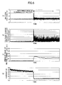
- Fig. 6 is a waveform diagram showing the transition of the voltage and the current of the battery 2 before and after an open failure (disconnection of the terminals) has occurred in the battery 2.
- Figs. 6-(a) through 6-(d) are waveforms generated at the same timing, representing one second per scale in the axis of abscissas. Note that the waveforms generated if an open failure has occurred inside the battery 2 are the same as that of Fig. 6 .
- Fig. 6-(a) is a diagram showing the transition of the output value of the voltage sensor 5.
- the ECU 10 controls the amount of electric power generated by the generator 1 so that the voltage of the battery 2 is controlled to be constant at approximately 14 V. If disconnection of the terminals of the battery 2 occurs, however, the voltage temporarily rises up to approximately 16.5 V at disconnection of the terminals and then the change in voltage larger than that before disconnection of the terminals is caused to continue although the ECU 10 attempts to maintain the voltage constant.
- Fig. 6-(b) is a diagram showing the transition of the change amount of the output value of the voltage sensor 5 as shown in Fig. 6-(a) .
- the voltage change amount ⁇ V before disconnection of the terminals of the battery 2 varies at an amount less than 0.1 V, while that after disconnection of the terminals of the battery 2 increases to an amount approximately between 0.3 and 0.5 V. Note that the voltage change amount ⁇ V refers to a change amount of the voltage per micro unit time.
- Fig. 6-(c) is a diagram showing an smoothed value of the voltage change amount ⁇ V of the battery 2 as shown in Fig. 6-(b) .
- the ECU 10 causes the output value of the voltage sensor 5 as shown in Fig. 6-(a) to pass through a low-pass filter or the like and then calculates the smoothed value ⁇ Vsm (namely, the value as shown in Fig. 6-(c) ) of the voltage change amount ⁇ V as shown in Fig. 6-(b) .
- Fig. 6-(d) is a diagram showing the transition of the output value of the current sensor 4. It shows that a current between 30 and 40 A flows from the battery 2 before disconnection of the terminals of the battery 2. If disconnection of the terminals occurs in the battery 2, however, it is not possible for the battery 2 to be charged and discharged, thereby causing the charging and discharging current value (battery current) detected by the current sensor 4 to be almost zero.
- the ECU 10 determines that an open failure has occurred in the battery 2 and an intermediate fixed failure has occurred in the current sensor 4.
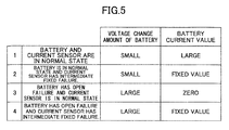
- Fig. 5 is a table summarizing the relationship between the voltage change amount of the battery 2 detected by the voltage sensor 5 and the battery current value detected by the current sensor 4 when an open failure has occurred in the battery 2 and/or an intermediate fixed failure has occurred in the current sensor 4.
- four combinations can be considered. (1) If both of the battery 2 and the current sensor 4 are in a normal state, the voltage change amount of the battery is detected small as shown in Fig. 6-(b) and the battery current value is detected large as shown in Fig. 6-(d) . (2) If the battery 2 is in a normal state and the current sensor 4 has an intermediate fixed failure, the voltage change amount of the battery is detected small as shown in Fig.
- the voltage change amount of the battery is detected large and the battery current is detected at a fixed value (the change amount of the battery current is detected small), it can be recognized that at least an open failure has occurred in the battery 2. Furthermore, if the voltage change amount of the battery is detected small and the battery current is detected at a fixed value (the change amount of the battery current is detected small), it can be recognized that an open failure has occurred in the current sensor 4.
- Fig. 2 is an example of an overall flow of an abnormality determination process of the abnormality determination device of the power supply of the present embodiment.
- the ECU 10 executes processing for determining whether an open failure has occurred in the battery 2 (step 100) and then executes processing for determining whether an intermediate fixed failure has occurred in the current sensor 4 (step 200). This flow is repeated at a predetermined cycle, in a continuous fashion, or in a random manner.
- a detailed description of each step in Fig. 2 is given below.
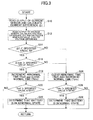
- Fig. 3 is an example of a flow of the determination process for an open failure in the battery 2.
- the ECU 10 executes processing in accordance with the flow in Fig. 3 .
- the ECU 10 calculates a current difference ⁇ I based on the result obtained by reading the output value of the current sensor 4 (step 10).
- the current difference ⁇ I calculated at this time is the difference between the reading value in the previous step 10 and that in the present step 10.
- the current difference ⁇ I may be an average change amount of the reading value in any predetermined time (for example, two seconds) while the generator 1 is in operation for generating electric power.
- the ECU 10 calculates a voltage difference ⁇ V by reading the output value of the voltage sensor 5 (step 12).
- the voltage difference ⁇ V calculated at this time is the smoothed value ⁇ Vsm of the voltage change amount ⁇ V as shown in Fig. 6-(c) .
- the ECU 10 determines whether the current difference ⁇ I is smaller than the specified value XI (step 14) and determines whether the smoothed value ⁇ Vsm of the voltage difference is larger than the specified value XVsm (step 16).
- the abnormal time Tbtf and the normal time Tbtn refer to internal variables of the program of the ECU 10. Then, it is determined whether the abnormal time Tbtf is larger than the specified value XTBTF (for example, three seconds) (step 20).
- the specified value XTBTF refers to a threshold value that sets a time until it is determined that an open failure has occurred in the battery 2.
- step 20; Yes If the abnormal time Tbtf is larger than the specified value XTBTF (step 20; Yes), it is determined that an open failure has occurred in the battery 2 because the voltage change amount of the battery is large and the battery current is set to a fixed value (the change amount of the battery current is small). If the abnormal time Tbtf is not larger than the specified value XTBTF (step 20; No), the determination of an open failure in the battery 2 is not made.
- the specified value XTBTN refers to a threshold value that sets a time until it is determined that the battery 2 is in a normal state.
- step 26 If the normal time Tbtn is larger than the specified value XTBTN (step 26; Yes), it is determined that the battery 2 is in a normal state because the battery current is not set to a fixed value but the change amount thereof is large, or because the battery current is set to a fixed value but the change amount of the battery voltage is small (step 28). If the normal time Tbtn is not larger than the specified value XTBTN (step 28; No), the determination whether the battery 2 is in a normal state is not made.
- step 100 of the flow in Fig. 2 is finished, and then the process advances to the determination process for an intermediate fixed failure in the current sensor 4 in step 200.
- the flow as shown in Fig. 3 is repeated until it is determined that an open failure has occurred in the battery 2 in step 22 or the battery 2 is in a normal state in step 28.
- the process of step 100 of the flow in Fig. 2 is finished and then the process advances to the determination process for an intermediate fixed failure in the current sensor 4 in step 200.
- Fig. 4 is an example of a flow of the determination process for an intermediate fixed failure in the current sensor 4.
- the ECU 10 executes processing in accordance with the flow in Fig. 4 .
- the ECU 10 refers to the above-described abnormal time Tbtf and confirms whether the abnormal time Tbtf is zero (step 40). If the abnormal time Tbtf is not zero, this flow is finished. If the abnormal time Tbtf is zero, it is confirmed whether the battery 2 is in a normal state, i.e., it is confirmed whether the battery 2 has been determined to be in a normal state in step 28 of Fig. 3 (step 42). More specifically, the process advances to step 48 after it has been confirmed that the battery 2 is in a normal state (no open failure has occurred in the battery 2) in steps 40 and 42.
- Fig. 7 is a diagram for illustrating the calculation of the internal resistance R.
- the ECU 10 samples the output value of the current sensor 4 and the output value of the voltage sensor 5 at a predetermined timing while the generator 1 is in operation for generating electric power.
- the output value of the current sensor 4 and the output value of the voltage sensor 5 at the same sampling time can be expressed as one point of correlation data on a two-dimensional plane as shown in Fig. 7 .
- the line Lr as shown in Fig. 7 is drawn to be applied to plural correlation data points plotted in Fig.
- the internal resistance R corresponds to the inclination of the regression curve Lr, thereby making it possible to determine whether an intermediate fixed failure has occurred in the current sensor 4 based on the size of the internal resistance R calculated as described above. Note that any suitable method other than the above-described one may be used for calculating the internal resistance.
- the ECU 10 determines whether the internal resistance R is smaller than the predetermined threshold value XR (step 50). If the internal resistance R is smaller than the threshold value XR, it is determined that the current sensor 4 is in a normal state because the inclination of the regression curve Lr is small (step 52). If the internal resistance R is not smaller than the threshold value XR, it is determined that an intermediate fixed failure has occurred in the current sensor 4 because the inclination of the regression curve Lr is large (step 54). Note that the sensitivity to determine an intermediate fixed failure in the current sensor 4 is changed depending on the threshold value XR. As the threshold value XR is set to be smaller, it becomes easier to determine the occurrence of an intermediate fixed failure in the current sensor 4. When the flow as shown in Fig. 4 is finished, the process of step 200 of the flow in Fig. 2 is finished.
- the abnormality determination device of the power supply of the present embodiment has no possibility of erroneously determining that an intermediate fixed failure has occurred in the current sensor 4 despite the fact that an open failure has occurred in the battery 2 and makes it possible to discriminate between an open failure in the battery 2 and an intermediate fixed failure in the battery sensor 4.
- the determination of an intermediate fixed failure in the current sensor 4 may be made based on the output value of the battery current I instead of the internal resistance R as shown in Fig. 4 . If the sampling data of the output value of the battery current I in any predetermined time falls within a small predetermined range while the generator 1 is in operation for generating electric power, it is equivalent to the large inclination of the regression curve Lr, thereby making it possible to determine that an intermediate fixed failure has occurred in the current sensor 4.
Landscapes
- Physics & Mathematics (AREA)
- General Physics & Mathematics (AREA)
- Secondary Cells (AREA)
- Charge And Discharge Circuits For Batteries Or The Like (AREA)
- Tests Of Electric Status Of Batteries (AREA)
- Electric Propulsion And Braking For Vehicles (AREA)
- Control Of Charge By Means Of Generators (AREA)
Applications Claiming Priority (2)
| Application Number | Priority Date | Filing Date | Title |
|---|---|---|---|
| JP2006050035A JP4501873B2 (ja) | 2006-02-27 | 2006-02-27 | 電源装置の異常判定装置及び異常判定方法 |
| PCT/JP2007/052046 WO2007097190A1 (fr) | 2006-02-27 | 2007-02-06 | Dispositif de jugement d'anormalite et procede correspondant pour une unite d'alimentation de courant |
Publications (3)
| Publication Number | Publication Date |
|---|---|
| EP1990645A1 true EP1990645A1 (fr) | 2008-11-12 |
| EP1990645A4 EP1990645A4 (fr) | 2012-11-21 |
| EP1990645B1 EP1990645B1 (fr) | 2014-03-26 |
Family
ID=38437229
Family Applications (1)
| Application Number | Title | Priority Date | Filing Date |
|---|---|---|---|
| EP07713875.8A Ceased EP1990645B1 (fr) | 2006-02-27 | 2007-02-06 | Dispositif de jugement d'anormalite et procede correspondant pour une unite d'alimentation de courant |
Country Status (5)
| Country | Link |
|---|---|
| US (1) | US7821234B2 (fr) |
| EP (1) | EP1990645B1 (fr) |
| JP (1) | JP4501873B2 (fr) |
| CN (2) | CN101326446B (fr) |
| WO (1) | WO2007097190A1 (fr) |
Cited By (5)
| Publication number | Priority date | Publication date | Assignee | Title |
|---|---|---|---|---|
| FR3040791A1 (fr) * | 2015-09-07 | 2017-03-10 | Peugeot Citroen Automobiles Sa | Dispositif de detection de caracteristique(s) d'une batterie |
| EP2518522A4 (fr) * | 2009-12-25 | 2017-06-28 | Toyota Jidosha Kabushiki Kaisha | Dispositif de détection d'anomalie pour batterie assemblée |
| WO2018046166A1 (fr) * | 2016-09-06 | 2018-03-15 | Robert Bosch Gmbh | Dispositif et procédé de détection d'une liaison électrique manquante entre un accumulateur électrique et un système d'alimentation électrique, notamment un réseau de bord d'un véhicule à moteur |
| DE112013006920B4 (de) | 2013-04-09 | 2019-07-04 | Mitsubishi Electric Corporation | Ausfall-Detektionsvorrichtung für Spannungssensor |
| FR3131638A1 (fr) * | 2022-01-06 | 2023-07-07 | Psa Automobiles Sa | Surveillance d’une batterie principale d’un système pour la détection d’un dysfonctionnement |
Families Citing this family (65)
| Publication number | Priority date | Publication date | Assignee | Title |
|---|---|---|---|---|
| JP5102483B2 (ja) * | 2006-11-29 | 2012-12-19 | プライムアースEvエナジー株式会社 | 異常検出装置、異常検出方法、及び異常検出プログラム |
| JP4274382B2 (ja) * | 2007-03-02 | 2009-06-03 | 株式会社日本自動車部品総合研究所 | 車両用二次電池の内部抵抗算出方法 |
| TWI352201B (en) * | 2008-04-14 | 2011-11-11 | Inventec Appliances Corp | A method and recording medium for early warning of |
| KR100969567B1 (ko) * | 2008-07-04 | 2010-07-12 | 포항공과대학교 산학협력단 | 이동 통신 단말기의 비정상적인 배터리 소모 검출 방법 및장치 |
| JP5231892B2 (ja) * | 2008-08-04 | 2013-07-10 | 株式会社東芝 | 電気車用電源装置 |
| JP5369607B2 (ja) * | 2008-10-23 | 2013-12-18 | 富士電機株式会社 | 無停電電源装置および無停電電源装置の遮断方法 |
| JP5369608B2 (ja) * | 2008-10-23 | 2013-12-18 | 富士電機株式会社 | 無停電電源装置および無停電電源装置の選択遮断方法 |
| CN102033205B (zh) * | 2009-09-30 | 2013-01-30 | 比亚迪股份有限公司 | 一种车辆动力电池的故障检测系统及检测方法 |
| JP2011101483A (ja) * | 2009-11-05 | 2011-05-19 | Mitsubishi Electric Corp | 車両用駆動電源装置 |
| JP4820461B2 (ja) * | 2009-12-10 | 2011-11-24 | パナソニック株式会社 | 分散型電源システム |
| JP5412353B2 (ja) * | 2010-03-29 | 2014-02-12 | 新電元工業株式会社 | 内燃機関点火装置 |
| US10634731B2 (en) | 2010-04-15 | 2020-04-28 | FedEx Supply Chain Logistics & Electronics, Inc. | Systems and methods for testing power supplies |
| US8988098B2 (en) * | 2010-04-15 | 2015-03-24 | Atc Logistics & Electronics, Inc. | Systems and methods for modular testing of chargers |
| US9400314B2 (en) * | 2010-04-15 | 2016-07-26 | Atc Logistics & Electronics, Inc. | Extended systems and methods for testing power supplies |
| KR20120035205A (ko) * | 2010-08-02 | 2012-04-13 | 파나소닉 주식회사 | 분산형 전원 시스템 및 그 제어 방법 |
| WO2012086057A1 (fr) * | 2010-12-24 | 2012-06-28 | トヨタ自動車株式会社 | Système d'alimentation électrique, véhicule doté de celui-ci et procédé de commande d'appareil de stockage d'énergie |
| US9019067B2 (en) * | 2010-12-30 | 2015-04-28 | Sargent Manufacturing Company | Electronic lock with power failure control circuit |
| EP2662698B1 (fr) | 2011-01-06 | 2023-07-26 | Furukawa Electric Co., Ltd. | Dispositif de détection d'état de batterie secondaire et procédé de détection d'état de batterie secondaire |
| JP5353915B2 (ja) * | 2011-02-01 | 2013-11-27 | 株式会社デンソー | 電池電圧監視装置 |
| CN102646976A (zh) * | 2011-02-22 | 2012-08-22 | 台达电子工业股份有限公司 | 多电源并联供电系统 |
| US20130076131A1 (en) * | 2011-04-08 | 2013-03-28 | Panasonic Corporation | Distributed power generation system and operation method thereof |
| JP2012252823A (ja) * | 2011-06-01 | 2012-12-20 | Toyota Industries Corp | 2次電池劣化度推定装置及びその方法 |
| CN102253345A (zh) * | 2011-06-04 | 2011-11-23 | 南昌航空大学 | 一种利用电致荧光强度测量太阳电池理想因子的装置及方法 |
| JP5907768B2 (ja) * | 2012-01-25 | 2016-04-26 | シャープ株式会社 | 画像形成装置のエラー検知回路 |
| US9356548B2 (en) | 2012-05-10 | 2016-05-31 | Denso Corporation | Vibration damping control apparatus for vehicle, vibration damping control system for vehicle, and vehicle motion control apparatus |
| CN102735369A (zh) * | 2012-06-21 | 2012-10-17 | 奇瑞汽车股份有限公司 | 一种水温传感器的诊断方法 |
| CN103884984B (zh) * | 2012-12-19 | 2017-06-20 | 北京创智信科科技股份有限公司 | 蓄电池故障信息的生成方法 |
| CN103884986B (zh) * | 2012-12-19 | 2017-07-18 | 北京创智信科科技股份有限公司 | 蓄电池故障的检测方法 |
| DE102014106218B4 (de) | 2013-05-09 | 2021-11-25 | Denso Corporation | Drehende elektrische Maschine für ein Fahrzeug |
| CN103698727B (zh) * | 2013-07-10 | 2016-06-08 | 奇瑞新能源汽车技术有限公司 | 一种电动车电池电流传感器短路故障监控方法 |
| JP6155949B2 (ja) * | 2013-08-09 | 2017-07-05 | 株式会社デンソー | ガスセンサ制御装置 |
| US10124789B2 (en) * | 2013-08-30 | 2018-11-13 | Ford Global Technologies, Llc | In-range current sensor fault detection |
| US9948125B2 (en) | 2013-11-07 | 2018-04-17 | Stored Energy Systems, a Limited Liability Company | Systems and methods for self-contained automatic battery charging and battery-life-extension charging |
| US9466995B2 (en) | 2013-11-07 | 2016-10-11 | Stored Energy Systems, a Limited Liability Company | Self-contained automatic battery charging systems and methods |
| JP5852087B2 (ja) * | 2013-11-25 | 2016-02-03 | プライムアースEvエナジー株式会社 | 使用済み二次電池の選択方法、及び、組電池の製造方法 |
| JP2015120462A (ja) * | 2013-12-25 | 2015-07-02 | ダイハツ工業株式会社 | 車両の制御装置 |
| KR101916046B1 (ko) * | 2013-12-30 | 2018-11-07 | 현대자동차 주식회사 | 전압 센서 고장 감지 방법 |
| CN103699763B (zh) * | 2014-01-20 | 2016-06-08 | 哈尔滨工业大学 | 基于最小二乘拟合的开关电源健康状态评估方法 |
| JP5971265B2 (ja) | 2014-01-20 | 2016-08-17 | トヨタ自動車株式会社 | 昇圧コンバータの制御装置 |
| US9606160B2 (en) * | 2014-03-05 | 2017-03-28 | GM Global Technology Operations LLC | Detection of stuck in range sensor and method |
| JP6270564B2 (ja) * | 2014-03-17 | 2018-01-31 | マーレエレクトリックドライブズジャパン株式会社 | バッテリー充電装置におけるバッテリー外れ検出方法及びそのバッテリー充電装置 |
| JP6179440B2 (ja) | 2014-03-28 | 2017-08-16 | トヨタ自動車株式会社 | 車両制御装置 |
| JP6287934B2 (ja) | 2014-04-03 | 2018-03-07 | トヨタ自動車株式会社 | 車両の制御装置 |
| DE102014210648A1 (de) * | 2014-06-04 | 2015-12-17 | Robert Bosch Gmbh | Batteriesystem |
| FR3027403B1 (fr) * | 2014-10-17 | 2017-04-21 | Renault Sas | Procede pour diagnostiquer des defaillances dans un ensemble de batteries stationnaires |
| CN104407268A (zh) * | 2014-11-27 | 2015-03-11 | 国家电网公司 | 基于电量、电压和电流异常分析的异常用电判断方法 |
| KR20170030254A (ko) * | 2015-09-09 | 2017-03-17 | 에스케이하이닉스 주식회사 | 전원전압 센싱 장치 |
| JP6220904B2 (ja) * | 2016-01-14 | 2017-10-25 | 本田技研工業株式会社 | 蓄電装置 |
| CN105629178A (zh) * | 2016-01-28 | 2016-06-01 | 广州优维电子科技有限公司 | 一种蓄电池组开路监测装置和方法 |
| EP3503341B1 (fr) * | 2017-08-25 | 2021-08-04 | Guangdong Oppo Mobile Telecommunications Corp., Ltd. | Équipement terminal, système de batterie et dispositif de détection d'anomalie de batterie |
| EP3657591B1 (fr) * | 2017-08-25 | 2021-07-14 | Guangdong Oppo Mobile Telecommunications Corp., Ltd. | Dispositif terminal et procédé et système de surveillance de sécurité de batterie associés |
| US10698033B2 (en) * | 2017-12-21 | 2020-06-30 | Robert Bosch Battery Systems, Llc | Sensor fault detection using paired sample correlation |
| US11351887B2 (en) * | 2017-12-22 | 2022-06-07 | Sanyo Electric Co., Ltd. | Management device and power supply system |
| JP7387250B2 (ja) * | 2018-01-23 | 2023-11-28 | 三菱自動車工業株式会社 | 電池監視システム |
| JP6779949B2 (ja) * | 2018-09-04 | 2020-11-04 | 本田技研工業株式会社 | 蓄電システム、および異常判定方法 |
| CN109814039B (zh) * | 2019-01-10 | 2022-09-09 | 中国移动通信集团海南有限公司 | 一种蓄电池组开路检测方法、装置及计算机可读存储介质 |
| CN111856331B (zh) * | 2019-04-26 | 2023-06-30 | 长城汽车股份有限公司 | 车辆的充电线路的断路故障检测方法及检测装置、车辆 |
| US11670952B2 (en) * | 2019-10-18 | 2023-06-06 | Fca Us Llc | Voltage estimation for automotive battery charging system control |
| CN111030225A (zh) * | 2019-12-20 | 2020-04-17 | 博士德科技(江苏)有限公司 | 一种双向电源装置及其控制方法 |
| CN111596248A (zh) * | 2020-06-01 | 2020-08-28 | 安徽江淮汽车集团股份有限公司 | 分流器电流采集故障判断方法、装置、设备及存储介质 |
| US11653127B2 (en) * | 2020-06-10 | 2023-05-16 | Bridgestone Mobility Solutions B.V. | Monitoring voltage measurements for a vehicle battery |
| KR20220062223A (ko) | 2020-11-06 | 2022-05-16 | 현대자동차주식회사 | 차량 배터리 관리 시스템 및 방법 |
| AU2023298147B2 (en) | 2022-06-30 | 2025-04-17 | Stored Energy Systems, LLC | Systems and methods for extending battery life |
| CN115436729B (zh) * | 2022-09-01 | 2025-02-11 | 杭州云酷智能科技有限公司 | 一种设备检测方法、装置、计算机设备及可读存储介质 |
| EP4603344A1 (fr) * | 2022-10-12 | 2025-08-20 | Robert Bosch GmbH | Unité de commande de pression hydraulique, système de freinage et procédé de diagnostic |
Family Cites Families (7)
| Publication number | Priority date | Publication date | Assignee | Title |
|---|---|---|---|---|
| JPH07184325A (ja) * | 1993-12-24 | 1995-07-21 | Hitachi Koki Co Ltd | 電池の充電装置 |
| JP3311268B2 (ja) * | 1997-03-14 | 2002-08-05 | 本田技研工業株式会社 | 電流センサの故障判定装置 |
| JP3936169B2 (ja) * | 2001-11-06 | 2007-06-27 | パナソニック・イーブイ・エナジー株式会社 | 組電池システムの異常検出方法及び装置 |
| JP4092904B2 (ja) * | 2001-11-09 | 2008-05-28 | トヨタ自動車株式会社 | 組電池の状態判定装置 |
| US6992487B1 (en) * | 2003-05-29 | 2006-01-31 | La Marche Manufacturing Co. | Arrangement for testing battery while under load and charging |
| CN100446372C (zh) * | 2004-07-07 | 2008-12-24 | 丰田自动车株式会社 | 能够检测流过驱动电路的电流的异常的电源装置 |
| JP2006040689A (ja) * | 2004-07-27 | 2006-02-09 | Auto Network Gijutsu Kenkyusho:Kk | バッテリ状態管理装置 |
-
2006
- 2006-02-27 JP JP2006050035A patent/JP4501873B2/ja not_active Expired - Fee Related
-
2007
- 2007-02-06 CN CN2007800006063A patent/CN101326446B/zh not_active Expired - Fee Related
- 2007-02-06 US US11/887,206 patent/US7821234B2/en active Active
- 2007-02-06 CN CN201110184046XA patent/CN102253348B/zh not_active Expired - Fee Related
- 2007-02-06 EP EP07713875.8A patent/EP1990645B1/fr not_active Ceased
- 2007-02-06 WO PCT/JP2007/052046 patent/WO2007097190A1/fr not_active Ceased
Cited By (8)
| Publication number | Priority date | Publication date | Assignee | Title |
|---|---|---|---|---|
| EP2518522A4 (fr) * | 2009-12-25 | 2017-06-28 | Toyota Jidosha Kabushiki Kaisha | Dispositif de détection d'anomalie pour batterie assemblée |
| DE112013006920B4 (de) | 2013-04-09 | 2019-07-04 | Mitsubishi Electric Corporation | Ausfall-Detektionsvorrichtung für Spannungssensor |
| US10551468B2 (en) | 2013-04-09 | 2020-02-04 | Mitsubishi Electric Corporation | Failure detection apparatus for voltage sensor |
| FR3040791A1 (fr) * | 2015-09-07 | 2017-03-10 | Peugeot Citroen Automobiles Sa | Dispositif de detection de caracteristique(s) d'une batterie |
| WO2018046166A1 (fr) * | 2016-09-06 | 2018-03-15 | Robert Bosch Gmbh | Dispositif et procédé de détection d'une liaison électrique manquante entre un accumulateur électrique et un système d'alimentation électrique, notamment un réseau de bord d'un véhicule à moteur |
| CN109642921A (zh) * | 2016-09-06 | 2019-04-16 | 罗伯特·博世有限公司 | 用于识别储能器与能量供应系统、尤其是机动车的车载电网缺少电连接的设备和方法 |
| US11204381B2 (en) | 2016-09-06 | 2021-12-21 | Robert Bosch Gmbh | Device and method for detecting a missing electrical connection of an energy store to an energy-supply system, particularly an electrical system of a motor vehicle |
| FR3131638A1 (fr) * | 2022-01-06 | 2023-07-07 | Psa Automobiles Sa | Surveillance d’une batterie principale d’un système pour la détection d’un dysfonctionnement |
Also Published As
| Publication number | Publication date |
|---|---|
| US20090128157A1 (en) | 2009-05-21 |
| CN101326446B (zh) | 2011-09-28 |
| EP1990645B1 (fr) | 2014-03-26 |
| CN102253348A (zh) | 2011-11-23 |
| JP4501873B2 (ja) | 2010-07-14 |
| CN102253348B (zh) | 2012-10-03 |
| EP1990645A4 (fr) | 2012-11-21 |
| US7821234B2 (en) | 2010-10-26 |
| CN101326446A (zh) | 2008-12-17 |
| WO2007097190A1 (fr) | 2007-08-30 |
| JP2007225562A (ja) | 2007-09-06 |
Similar Documents
| Publication | Publication Date | Title |
|---|---|---|
| EP1990645B1 (fr) | Dispositif de jugement d'anormalite et procede correspondant pour une unite d'alimentation de courant | |
| CN102576040B (zh) | 电压监测器 | |
| JP4001072B2 (ja) | 車両用発電システム | |
| EP3270173B1 (fr) | Dispositif de gestion de batterie, circuit de surveillance de batterie, système de commande | |
| JP2001116776A (ja) | 電池電圧測定装置 | |
| US10974611B2 (en) | Motor-driven vehicle | |
| CN105480297B (zh) | 电动转向装置 | |
| JP2019092310A (ja) | 車両用充電装置 | |
| KR20090039891A (ko) | 하이브리드 차량용 프리차징 제어방법 | |
| CN112292288A (zh) | 车载用的电源控制装置、电源装置及车辆的控制方法 | |
| JP2007252082A (ja) | 電源制御装置およびリレーの異常検出方法 | |
| US8463474B2 (en) | Method and system for controlling motor torque in hybrid vehicles | |
| JP2001147260A (ja) | 蓄電装置の残容量検出装置 | |
| JP2007024825A (ja) | 電流センサの故障診断装置 | |
| JP4680032B2 (ja) | 車両用電源装置 | |
| JP5326333B2 (ja) | 車両用電源システム | |
| JP2005348483A (ja) | 燃料電池車用地絡検知装置 | |
| US12436197B2 (en) | Control device, control method, and non- transitory storage medium | |
| JP6206292B2 (ja) | 電源システム | |
| JP7655212B2 (ja) | 電源システム | |
| JP2020068605A (ja) | 車両用電源装置の診断装置 | |
| JP2002272012A (ja) | 車両用電子制御装置 | |
| JP2010088181A (ja) | 車両用電源装置 | |
| JP2011076777A (ja) | 電池監視装置 | |
| JP2026055469A (ja) | 電流センサの誤組み付け検出方法 |
Legal Events
| Date | Code | Title | Description |
|---|---|---|---|
| PUAI | Public reference made under article 153(3) epc to a published international application that has entered the european phase |
Free format text: ORIGINAL CODE: 0009012 |
|
| 17P | Request for examination filed |
Effective date: 20070928 |
|
| AK | Designated contracting states |
Kind code of ref document: A1 Designated state(s): DE FR GB |
|
| DAX | Request for extension of the european patent (deleted) | ||
| RBV | Designated contracting states (corrected) |
Designated state(s): DE FR GB |
|
| A4 | Supplementary search report drawn up and despatched |
Effective date: 20121024 |
|
| RIC1 | Information provided on ipc code assigned before grant |
Ipc: G01R 19/165 20060101ALI20121019BHEP Ipc: G01R 31/36 20060101AFI20121019BHEP |
|
| RAP1 | Party data changed (applicant data changed or rights of an application transferred) |
Owner name: TOYOTA JIDOSHA KABUSHIKI KAISHA |
|
| RIC1 | Information provided on ipc code assigned before grant |
Ipc: G01R 19/165 20060101ALI20130809BHEP Ipc: G01R 31/36 20060101AFI20130809BHEP Ipc: G01R 31/40 20060101ALI20130809BHEP |
|
| GRAP | Despatch of communication of intention to grant a patent |
Free format text: ORIGINAL CODE: EPIDOSNIGR1 |
|
| INTG | Intention to grant announced |
Effective date: 20131001 |
|
| GRAS | Grant fee paid |
Free format text: ORIGINAL CODE: EPIDOSNIGR3 |
|
| GRAA | (expected) grant |
Free format text: ORIGINAL CODE: 0009210 |
|
| AK | Designated contracting states |
Kind code of ref document: B1 Designated state(s): DE FR GB |
|
| REG | Reference to a national code |
Ref country code: GB Ref legal event code: FG4D |
|
| REG | Reference to a national code |
Ref country code: DE Ref legal event code: R096 Ref document number: 602007035758 Country of ref document: DE Effective date: 20140508 |
|
| REG | Reference to a national code |
Ref country code: DE Ref legal event code: R084 Ref document number: 602007035758 Country of ref document: DE |
|
| REG | Reference to a national code |
Ref country code: GB Ref legal event code: 746 Effective date: 20141119 |
|
| REG | Reference to a national code |
Ref country code: DE Ref legal event code: R097 Ref document number: 602007035758 Country of ref document: DE |
|
| REG | Reference to a national code |
Ref country code: DE Ref legal event code: R084 Ref document number: 602007035758 Country of ref document: DE Effective date: 20141117 |
|
| PLBE | No opposition filed within time limit |
Free format text: ORIGINAL CODE: 0009261 |
|
| STAA | Information on the status of an ep patent application or granted ep patent |
Free format text: STATUS: NO OPPOSITION FILED WITHIN TIME LIMIT |
|
| 26N | No opposition filed |
Effective date: 20150106 |
|
| REG | Reference to a national code |
Ref country code: DE Ref legal event code: R097 Ref document number: 602007035758 Country of ref document: DE Effective date: 20150106 |
|
| REG | Reference to a national code |
Ref country code: FR Ref legal event code: PLFP Year of fee payment: 10 |
|
| REG | Reference to a national code |
Ref country code: FR Ref legal event code: PLFP Year of fee payment: 11 |
|
| REG | Reference to a national code |
Ref country code: FR Ref legal event code: PLFP Year of fee payment: 12 |
|
| PGFP | Annual fee paid to national office [announced via postgrant information from national office to epo] |
Ref country code: FR Payment date: 20190111 Year of fee payment: 13 Ref country code: GB Payment date: 20190206 Year of fee payment: 13 |
|
| GBPC | Gb: european patent ceased through non-payment of renewal fee |
Effective date: 20200206 |
|
| PG25 | Lapsed in a contracting state [announced via postgrant information from national office to epo] |
Ref country code: FR Free format text: LAPSE BECAUSE OF NON-PAYMENT OF DUE FEES Effective date: 20200229 Ref country code: GB Free format text: LAPSE BECAUSE OF NON-PAYMENT OF DUE FEES Effective date: 20200206 |
|
| PGFP | Annual fee paid to national office [announced via postgrant information from national office to epo] |
Ref country code: DE Payment date: 20211230 Year of fee payment: 16 |
|
| P01 | Opt-out of the competence of the unified patent court (upc) registered |
Effective date: 20230427 |
|
| REG | Reference to a national code |
Ref country code: DE Ref legal event code: R119 Ref document number: 602007035758 Country of ref document: DE |
|
| PG25 | Lapsed in a contracting state [announced via postgrant information from national office to epo] |
Ref country code: DE Free format text: LAPSE BECAUSE OF NON-PAYMENT OF DUE FEES Effective date: 20230901 |