EP1990681A2 - Cadre rétractable d'un écran de projection - Google Patents
Cadre rétractable d'un écran de projection Download PDFInfo
- Publication number
- EP1990681A2 EP1990681A2 EP08007707A EP08007707A EP1990681A2 EP 1990681 A2 EP1990681 A2 EP 1990681A2 EP 08007707 A EP08007707 A EP 08007707A EP 08007707 A EP08007707 A EP 08007707A EP 1990681 A2 EP1990681 A2 EP 1990681A2
- Authority
- EP
- European Patent Office
- Prior art keywords
- arm
- projection screen
- retractable
- upper support
- receiving case
- Prior art date
- Legal status (The legal status is an assumption and is not a legal conclusion. Google has not performed a legal analysis and makes no representation as to the accuracy of the status listed.)
- Withdrawn
Links
- 238000005096 rolling process Methods 0.000 claims description 68
- 230000001360 synchronised effect Effects 0.000 claims description 18
- 230000002457 bidirectional effect Effects 0.000 claims description 12
- 239000002184 metal Substances 0.000 claims description 9
- 229910052751 metal Inorganic materials 0.000 claims description 9
- 150000002739 metals Chemical class 0.000 claims description 9
- 239000007769 metal material Substances 0.000 description 9
- 239000000463 material Substances 0.000 description 7
- 238000004519 manufacturing process Methods 0.000 description 4
- 230000006870 function Effects 0.000 description 3
- 239000004753 textile Substances 0.000 description 3
- 230000002708 enhancing effect Effects 0.000 description 1
- 230000035807 sensation Effects 0.000 description 1
- 230000005236 sound signal Effects 0.000 description 1
Images


Classifications
-
- G—PHYSICS
- G03—PHOTOGRAPHY; CINEMATOGRAPHY; ANALOGOUS TECHNIQUES USING WAVES OTHER THAN OPTICAL WAVES; ELECTROGRAPHY; HOLOGRAPHY
- G03B—APPARATUS OR ARRANGEMENTS FOR TAKING PHOTOGRAPHS OR FOR PROJECTING OR VIEWING THEM; APPARATUS OR ARRANGEMENTS EMPLOYING ANALOGOUS TECHNIQUES USING WAVES OTHER THAN OPTICAL WAVES; ACCESSORIES THEREFOR
- G03B21/00—Projectors or projection-type viewers; Accessories therefor
- G03B21/54—Accessories
- G03B21/56—Projection screens
- G03B21/58—Projection screens collapsible, e.g. foldable; of variable area
Definitions
- the present invention relates to a retractable frame of projection screen, more particularly to a retractable frame of projection screen that is light in weight and small in volume and production cost thereof can be reduced.
- FIG. 1 which is a schematic view of a conventional retractable frame of projection screen in an unfolding status
- a plurality of supporting arms 1000 that are intercrossed to each other are provided, and two of the supporting arms 1000 disposed at the bottom end are respectively provided with a retractable arm 1010, the two retractable arms 1010 are served to enhance the supporting strength of the projection screen 1020 and facilitate folding and unfolding the projection screen 1020.
- retractable frame of projection screen needs quite a few of the supporting arms 1000 and the two retractable arms 1010 for enhancing the supporting strength of the projection screen 1020, but such retractable frame of projection screen is heavy in weight and large in volume and the production cost thereof is high. So a novel retractable frame of projection screen shall be invented.
- One object of the present invention is to provide a retractable frame of projection screen that is small in volume and light in weight and the production cost thereof can be reduced.
- the retractable frame of projection screen provided by the present invention comprising, a receiving case having an accommodating space; a cylinder having a cylinder retractable arm and the cylinder retractable arm being connected to the receiving case; a supporting arm, one end of the supporting arm being connected to the cylinder; a connecting member provided on the supporting arm; a main retractable arm having a main groove and a driven retractable arm, and the driven retractable arm having a retractable groove, wherein one end of the driven retractable arm is connected to the receiving case; an upper support for retaining the other end of the supporting arm and one end of the main retractable arm; and a screen axle provided on the upper support, a fixing axle being provided on the screen axle for folding a projection screen, wherein one end of the projection screen is connected to the upper support and the other end thereof is connected in the receiving case; when folding, the upper support is downwardly pressed, then the cylinder retractable arm is forced to inwardly retract by the cylinder and the driven retractable arm is inwardly retracted
- the retractable frame of projection screen comprising: a receiving case having an accommodating space; a bidirectional cylinder having a first cylinder retractable arm and a second cylinder retractable arm, wherein the first cylinder retractable arm is connected in one end of the receiving case; a supporting arm, one end thereof being connected to the second cylinder retractable arm of the bidirectional cylinder; a connecting member provided on the supporting arm; a main retractable arm having a main groove and a driven retractable arm, the driven retractable arm having a retractable groove, wherein one end of the driven retractable arm is connected to the receiving case; and an upper support for retaining the supporting arm and the other end of the main retractable arm; when folding, the upper support is downwardly pressed, when the first and the second cylinder retractable arms are inwardly retracted, the connecting member of the supporting arm is forced to downwardly slide alongside the main groove, so heights of the supporting arm and the main retractable arm are simultaneously lowered, and by connecting via the connecting member the heights of the
- the retractable frame of projection screen comprising: a receiving case having an accommodating space; a supporting arm, one end of the supporting arm being connected to one end of the receiving case, and a protruding tenon being provided on the supporting arm; a cylinder, one end of the cylinder being connected to the supporting arm, and the cylinder being provided with a cylinder retractable arm connected to one end of the receiving case; a driven supporting arm, one end of the driven supporting arm being connected to the other end of the receiving case, and a sliding groove being provided on the driven supporting arm for receiving the protruding tenon and allowing the protruding tenon sliding thereon; a main linkage arm, one end of the main linkage arm being connected to the other end of the supporting arm via a first pivot; a driven linkage arm, one end of the driven linkage arm being connected to the other end of the driven supporting arm via a second pivot; and an upper support for retaining the main linkage arm and the other end of the driven linkage arm; when
- the retractable frame of projection screen at least including: an upper support; a screen axle disposed on the upper support, a fixing axle being provided on the screen axle for folding a projection screen, wherein one end of the projection screen is connected to the upper support; a rolling device provided on the upper support or in a receiving case mentioned below for rolling the projection screen; and a receiving case, the receiving case has an accommodating space for retaining the other end of the projection screen.
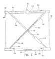
- FIG. 2 is schematic 3D view of a retractable frame of projection screen of one preferred embodiment of the present invention in an unfolding status
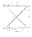
- FIG. 3 is schematic plane view of the retractable frame of projection screen of one preferred embodiment of the present invention in an unfolding status
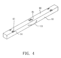
- FIG. 4 is schematic view of the retractable frame of projection screen of one preferred embodiment of the present invention in a folding status.
- the receiving case 10 has an accommodating space 11 for receiving the cylinder 20, the supporting arm 30, the connecting member 40, the main retractable arm 50, the upper support 60 and the screen axle 70, the receiving case 10 is preferably made of metal materials.
- the cylinder 20 has a cylinder retractable arm 21 connected to the receiving case 10, the cylinder retractable arm 21 is retractable within the cylinder 20.
- the working power of the cylinder retractable arm 21 is for example but not limited to be driven by an air force, oil force, electric force or a magnetic force and so on.
- One end of the supporting arm 30 is directly connected to one end of the upper support 60, for example but not limited to, being directly screwed on the upper support 60, and the supporting arm 30 is preferably made of metal materials.
- the connecting member 40 is provided on the supporting arm 30 for connecting the supporting arm 30 and the main retractable arm 50, the connecting member 40 can be, but not limited to, a pivot.
- the main retractable arm 50 is provided with a main groove 51 and a driven retractable arm 52, and a retractable groove 53 is provided on the driven retractable arm 52, wherein the main groove 51 is served to let the connecting member 40 slide, and one end of the driven retractable arm 52 is connected to the other end of the receiving case 10, and the main retractable arm 50 is preferably made of metal materials.
- the upper support 60 is served to retain the other end of the supporting arm 30 and one end of the main retractable arm 50, and the upper support 60 is preferably made of metal materials for allowing a projection screen 90 being hanged thereon, wherein the projection screen 90 can be, but not limited to, a textile screen, wherein one end of the projection screen 90 is connected to the upper support 60 and the other end thereof is connected to the receiving case 10.
- the position where one end of the cylinder retractable arm 21 is connected to the receiving case 10 is substantially parallel to the position where one end of the main retractable arm 50 is connected to the upper support 60, and the position where the other end of the supporting arm 30 is connected to the upper support 60 is substantially parallel to the position where the other end of the retractable groove 53 is connected to the receiving case 10, so when the retractable frame of projection screen provided by the present invention is unfolded, the appearance thereof is substantially in an X shape.
- the screen axle 70 is provided with a fixing axle 71 for folding the projection screen 90.
- the projection screen 90 can be rolled by the screen axle 70 with a mechanical means or an electromotive means.
- the receiving case 10 further comprises a handle 13, wherein two ends of the handle 13 are respectively provided with a second buckling device 14 with respect to one of two first buckling devices 61 provided on the upper support 60 so each of the second buckling devices 14 can be buckled with the corresponding first buckling device 61 of the upper support 60.
- the retractable frame of projection screen provided by the present invention further comprises a rolling device 80, the rolling device 80 can be disposed in the receiving case 10 or on the upper support 60 for rolling/unrolling the projection screen 90, and the rolling device 80 can be spring-biased by a spring member, a tubular motor or a synchronous motor; when the rolling device 80 is a tubular motor or a synchronous motor, the rolling device 80 can be controlled by a wired or wireless means, for example but not limited to, a radio frequency (RF) or an infrared (IR) control means or the combination thereof; when the rolling device 80 is spring-biased by a spring member and is disposed on the upper support 60, the rolling device 80 can be further provided with a manual braking device (not shown), a handle 81 is provided on the manual braking device; the screen axle 70 is on the same side as the rolling device 80, for example in the receiving case 10 or on the upper support 60.
- RF radio frequency
- IR infrared
- FIG. 4 which is schematic view of a retractable frame of projection screen provided by the present invention in a folding status
- the upper support 60 is downwardly pressed, then the cylinder retractable arm 21 is forced to inwardly retract by the cylinder 20 and the driven retractable arm 52 is inwardly retracted toward the main retractable arm 50 until the cylinder retractable arm 21 is fully received in the cylinder 20 and the driven retractable arm 52 is fully received in the main retractable arm 50, so the projection screen 90, the upper support 60, the supporting arm 30, the connecting member 40 and the main retractable arm 50 are received in the accommodating space 11.
- the handle 81 When unfolding the retractable frame of projection screen provide by the present invention, the handle 81 is upwardly pulled so the rolling device 80 is released or activated, and the upper support 60 is upwardly pulled to a pre-set height then the handle 81 is released, the projection screen 90 and the screen axle 70 are both held by the rolling device 80 (having same function as a manual braking device), then with a supporting strength from the cylinder retractable arm 21 a positioning status is therefore obtained.
- the receiving case 300 has an accommodating space 301 for receiving the bidirectional cylinder 310, the supporting arm 320, the connecting member 330, the main retractable arm 340, the upper support 350 and the screen axle 360 when in a folding status, and the receiving case 300 is preferably made of metal materials.
- the bidirectional cylinder 310 has a first cylinder retractable arm 311 and a second cylinder retractable arm 312, wherein the first retractable arm 311 is connected to one end of the receiving case 300, and materials of which the bidirectional cylinder 310 is made can be, but not limited to, metals.
- the working power of the first cylinder retractable arm 311 and second cylinder retractable arm 312 is for example but not limited to be driven by an air force, oil force, electric force or a magnetic force and so on, respectively.
- One end of the supporting arm 320 is connected to one end of the second cylinder retractable arm 312, and materials of which the supporting arm 320 is made can be, but not limited to, metals.
- the connecting member 330 is provided on the supporting arm 320, and the connecting member 330 can slide in a main groove 341 mentioned below.
- the supporting arm 320 and the main retractable arm 340 are connected by the connecting member 330 with a fashion of riveting, screwing or a protruding tenon.
- the main retractable arm 340 has a main groove 341 and a driven retractable arm 342, and the driven retractable arm 342 has a retractable groove 343, wherein the main groove 341 is served to let the connecting member 330 slide and one end of the driven retractable arm 342 is connected to the other end of the receiving case 300, the main retractable arm 340 is preferably made of metal materials.
- the upper support 350 is served to retain the other end of the main retractable arm 340 and one end of the supporting arm 320, and the upper support 350 is preferably made of metal materials for allowing a projection screen 90 being hanged thereon, wherein the other end of the projection screen 90 is connected to the receiving case 300, and the projection screen 90 can be, but not limited to, a textile screen.
- the screen axle 360 has a fixing axle 361 for folding the projection screen 90.
- the projection screen 90 can be rolled by the screen axle 360 with a mechanical means or an electromotive means.
- the receiving case 300 further comprises a handle 303, two ends of the handle 303 are respectively provided with a second buckling device 304 with respect to one of two first buckling devices 351 provided on the upper support 350 so each of the second buckling devices 304 can be buckled with the corresponding first buckling device 351 of the upper support 350.
- the retractable frame of projection screen provided by the present invention further comprises a rolling device 370, the rolling device 370 can be disposed in the receiving case 300 or on the upper support 350 for rolling/unrolling the projection screen 90, and the rolling device 370 can be spring-biased by a spring member, a tubular motor or a synchronous motor; when the rolling device 370 is a tubular motor or a synchronous motor, the rolling device 80 can be controlled with a wired or a wireless means, for example but not limited to, a radio frequency (RF) or an infrared (IR) control means or the combination thereof; when the rolling device 370 is spring-biased by a spring member and is disposed on the upper support 350, the rolling device 370 can be further provided with a manual braking device (not shown), a handle 371 is provided on the manual braking device; the screen axle 360 is on the same side as the rolling device 370, for example in the receiving case 300 or on the upper support 350.
- RF radio frequency
- IR infrared
- the upper support 350 When folding, the upper support 350 is downwardly pressed, the first cylinder retractable arm 311 and the second cylinder retractable arm 312 are inwardly retracted and the connecting member 330 of the supporting arm 320 is forced to downwardly slide alongside the main groove 341, so heights of the supporting arm 320 and the main retractable arm 340 are simultaneously lowered, by connecting via the connecting member 330 the heights of the supporting arm 320 and the main retractable arm 340 are simultaneously lowered till fully folded, so the projection screen 90, the upper support 350, the bidirectional cylinder 310, the supporting arm 320, the connecting member 330 and the main retractable arm 340 are received in the accommodating space 301.
- the positioning operation or operation of rolling/unrolling can be operated with an electromotive means.
- the receiving case 800 has an accommodating space 810 for receiving the upper support 860, the cylinder 820, the supporting arm 810, the main linkage arm 840 and the driven linkage arm 850, and the receiving case 800 is preferably made of metal materials.
- One end of the supporting arm 810 is connected to one end of the receiving case 800, a protruding tenon 81 is provided on the supporting arm 810, and materials of which the supporting arm 810 is made can be, but not limited to, metals.
- the cylinder 820 has a cylinder retractable arm 821, the cylinder retractable arm 821 is connected to one end of the receiving case 800, and materials of which the cylinder 820 is made can be, but not limited to, metals.
- the position where one end of the cylinder retractable arm 821 of the cylinder 820 is connected to the receiving case 800 is on the right hand side of the supporting arm 810.
- the working power of the cylinder retractable arm 821 is for example but not limited to be driven by an air force, oil force, electric force or a magnetic force and so on.
- One end of the driven supporting arm 830 is connected to the other end of the receiving case 800 and a sliding groove 831 is provided on the driven supporting arm 830 for receiving the protruding tenon 811 and allowing the protruding tenon 811 slides thereon, and materials of which the driven supporting arm 830 is made can be, but not limited to, metals.
- One end of the main linkage arm 840 can be connected to the other end of the supporting arm 810 via a first pivot 845, and materials of which the main linkage arm 840 is made can be, but not limited to, metals
- One end of the driven linkage arm 850 can be connected to the other end of the driven supporting arm 830 via a second pivot 855, and materials of which the driven linkage arm 850 is made can be, but not limited to, metals.
- the upper support 860 is served to retain the main linkage arm 840 and the other end of the driven linkage arm 850, and the upper support 860 is preferably made of metal materials for allowing a projection screen 90 being hanged thereon, wherein the projection screen 90 can be, but not limited to, a textile screen, one end of the projection screen 90 is connected to the upper support 860 and the other end thereof is connected to the receiving case 800.
- the position where one end of the first cylinder retractable arm 821 of the cylinder 820 is connected to the receiving case 800 is on the right hand side of the supporting arm 810.
- the screen axle 870 has a fixing axle 871 for folding the projection screen 90.
- the projection screen 90 can be rolled by the screen axle 870 with a mechanical means or an electromotive means.
- the receiving case 800 further comprises a handle 803, two ends of the handle 803 are respectively provided with a second buckling device 804 with respect to one of two first buckling device 861 provided on the upper support 860 so each of the second buckling devices 804 can be buckled with the corresponding first buckling device 861 of the upper support 860.
- the retractable frame of projection screen provided by the present invention further comprises a rolling device 880, the rolling device 880 can be disposed in the receiving case 800 or on the upper support 860 for rolling/unrolling the projection screen 90, and the rolling device 880 can be spring-biased by a spring member, a tubular motor or a synchronous motor; when the rolling device 880 is a tubular motor or a synchronous motor, the rolling device 880 can be controlled with a wired or a wireless means, for example but not limited to, a radio frequency (RF) or an infrared (IR) control means or the combination thereof; when the rolling device 880 is spring-biased by a spring member and is disposed on the upper support 860, the rolling device 880 can be further provided with a manual braking device (not shown), a handle 881 is provided on the manual braking device; the screen axle 870 is on the same side as the rolling device 880, for example in the receiving case 800 or on the upper support 860.
- RF radio frequency
- IR
- the positioning operation or operation of rolling/unrolling can be operated with an electromotive means.
- the present invention also provides a retractable frame of projection screen, wherein an upper support can be served to fold the projection screen 90, and the operation of positioning can be done via a manual braking device or a tubular motor or a synchronous motor.
- the retractable frame of projection screen provided by the present invention has advantages of small in volume, light in weight, and production cost thereof can be lowered so as to overcome disadvantages of a convention retractable frame of projection screen.
Landscapes
- Physics & Mathematics (AREA)
- General Physics & Mathematics (AREA)
- Overhead Projectors And Projection Screens (AREA)
Priority Applications (1)
| Application Number | Priority Date | Filing Date | Title |
|---|---|---|---|
| EP09014958A EP2163948A3 (fr) | 2007-05-09 | 2008-04-21 | Cadre rétractable d'un écran de projection |
Applications Claiming Priority (2)
| Application Number | Priority Date | Filing Date | Title |
|---|---|---|---|
| TW96207444U TWM321187U (en) | 2007-05-09 | 2007-05-09 | Expansion frame for display screen |
| TW97202977U TWM347000U (en) | 2008-02-20 | 2008-02-20 | Expansion frame for display screen |
Publications (2)
| Publication Number | Publication Date |
|---|---|
| EP1990681A2 true EP1990681A2 (fr) | 2008-11-12 |
| EP1990681A3 EP1990681A3 (fr) | 2009-06-24 |
Family
ID=39758714
Family Applications (2)
| Application Number | Title | Priority Date | Filing Date |
|---|---|---|---|
| EP09014958A Withdrawn EP2163948A3 (fr) | 2007-05-09 | 2008-04-21 | Cadre rétractable d'un écran de projection |
| EP08007707A Withdrawn EP1990681A3 (fr) | 2007-05-09 | 2008-04-21 | Cadre rétractable d'un écran de projection |
Family Applications Before (1)
| Application Number | Title | Priority Date | Filing Date |
|---|---|---|---|
| EP09014958A Withdrawn EP2163948A3 (fr) | 2007-05-09 | 2008-04-21 | Cadre rétractable d'un écran de projection |
Country Status (6)
| Country | Link |
|---|---|
| US (1) | US8031400B2 (fr) |
| EP (2) | EP2163948A3 (fr) |
| JP (1) | JP3143170U (fr) |
| KR (1) | KR20080099792A (fr) |
| AU (1) | AU2008202033A1 (fr) |
| CA (1) | CA2630205A1 (fr) |
Families Citing this family (35)
| Publication number | Priority date | Publication date | Assignee | Title |
|---|---|---|---|---|
| DE102009008543B4 (de) * | 2009-02-11 | 2014-05-22 | Airbus Operations Gmbh | Innenraumprojektion für Luftfahrzeuge |
| CN201464790U (zh) * | 2009-07-24 | 2010-05-12 | 广州美视晶莹银幕有限公司 | 一种携带自立式手动升降屏幕 |
| JP2011123233A (ja) * | 2009-12-10 | 2011-06-23 | Seiko Epson Corp | スクリーン装置 |
| US8107166B2 (en) * | 2010-03-25 | 2012-01-31 | Elite Screens China Corp. | Cabinet projection screen with automatic cover-lifting function |
| US8757819B2 (en) | 2010-06-25 | 2014-06-24 | Steelcase Inc. | Conveniently assemblable interactive systems and display device |
| KR101227644B1 (ko) * | 2010-08-10 | 2013-01-30 | 유상규 | 두루마리형 플렉서블 디스플레이 장치 |
| US8920252B2 (en) | 2010-08-18 | 2014-12-30 | People Ent Co., Ltd. | Frame structure for stage erection |
| JP2012053378A (ja) * | 2010-09-03 | 2012-03-15 | Seiko Epson Corp | スクリーン装置 |
| TWM403168U (en) * | 2010-12-06 | 2011-05-01 | Bright Supply Corp | Telescopic holder (5) display screen |
| US20120162760A1 (en) * | 2010-12-23 | 2012-06-28 | Yin-Wen Chen | Portable Projection Screen |
| CN202472230U (zh) * | 2012-03-07 | 2012-10-03 | 极品影视设备科技(深圳)有限公司 | 隐藏式投影幕 |
| US8526109B1 (en) * | 2012-06-29 | 2013-09-03 | Elite Screens Taiwan Co., Ltd. | Portable projection screen device |
| US9261903B1 (en) | 2013-09-06 | 2016-02-16 | Yemane Gedde | Retractable monitor computer assembly |
| US10724257B2 (en) * | 2014-11-26 | 2020-07-28 | Control Dynamics, Inc. | Vertically raising safety rail with dual curtain assembly |
| WO2016154481A1 (fr) * | 2015-03-26 | 2016-09-29 | Arovia, Inc. | Dispositif d'affichage à dépliement spontané |
| TWI723056B (zh) * | 2015-10-21 | 2021-04-01 | 美商艾維公司 | 可收縮彈出之顯示裝置 |
| KR102019509B1 (ko) * | 2016-09-05 | 2019-09-09 | 엘지전자 주식회사 | 디스플레이 디바이스 |
| US10403184B2 (en) | 2016-12-22 | 2019-09-03 | Waldemar Veazie, IV | Freestanding exhibit display |
| US20200022269A1 (en) * | 2016-12-30 | 2020-01-16 | Shenzhen Royole Technologies Co. Ltd. | Supporting assembly and display device |
| CN108870019A (zh) * | 2017-05-13 | 2018-11-23 | 银川上河图新技术研发有限公司 | 屏幕高低调节装置 |
| KR102464108B1 (ko) * | 2017-12-27 | 2022-11-07 | 엘지전자 주식회사 | 디스플레이 장치 |
| KR102573780B1 (ko) * | 2018-09-28 | 2023-08-31 | 엘지디스플레이 주식회사 | 표시 장치 |
| CN112684658B (zh) * | 2019-10-18 | 2025-06-24 | 青岛海信激光显示股份有限公司 | 投影屏幕及投影系统 |
| CN111999977B (zh) * | 2020-08-29 | 2022-02-22 | 芜湖宏嘉科技有限公司 | 一种智能教学用折叠式硬质投屏幕布 |
| JP7507045B2 (ja) * | 2020-09-14 | 2024-06-27 | 株式会社オカムラ | 立設スクリーン |
| USD978226S1 (en) * | 2020-11-10 | 2023-02-14 | Emart International Inc | Collapsible screen |
| USD939616S1 (en) * | 2020-11-29 | 2021-12-28 | Wuxi Donghui Video Equipment Co. Ltd. | Projection screen |
| KR102309469B1 (ko) * | 2020-12-22 | 2021-10-07 | 주식회사 닷밀 | 옥외형 전동스크린장치 |
| USD942528S1 (en) * | 2021-01-08 | 2022-02-01 | Caipeng Zou | Backdrop holder |
| USD947929S1 (en) * | 2021-01-14 | 2022-04-05 | Shaoxing Shangyu Yixiang Digital Equipment Co., Ltd | Collapsible chroma key panel |
| KR20220117374A (ko) * | 2021-02-15 | 2022-08-24 | 삼성디스플레이 주식회사 | 표시 장치 |
| CN113357979A (zh) * | 2021-07-19 | 2021-09-07 | 重庆零壹空间科技集团有限公司 | 一种挂弹机构及发射车 |
| KR20230076368A (ko) * | 2021-11-24 | 2023-05-31 | 엘지디스플레이 주식회사 | 표시 장치 |
| USD1017669S1 (en) * | 2021-12-10 | 2024-03-12 | Guangdong Acme Technology Co., Ltd. | Projection screen |
| US20250179868A1 (en) * | 2023-12-04 | 2025-06-05 | Patrick Luckett | Window Protective Systems |
Family Cites Families (14)
| Publication number | Priority date | Publication date | Assignee | Title |
|---|---|---|---|---|
| US1571661A (en) * | 1924-02-14 | 1926-02-02 | Foster Screen Co Inc | Rod or tube coupling |
| US1795442A (en) * | 1928-01-30 | 1931-03-10 | Albert L Raven | Motion-picture screen |
| GB437136A (en) * | 1934-07-09 | 1935-10-24 | Albert Sydney Wilson | Improvements in projection screens |
| US3144899A (en) * | 1962-02-26 | 1964-08-18 | Stewart La Mar Roy | Portable motion picture screen |
| US4068921A (en) * | 1976-01-07 | 1978-01-17 | Os Screen Co., Ltd. | Screen assembly |
| JPH0318529U (fr) * | 1989-07-05 | 1991-02-22 | ||
| US5274499A (en) * | 1992-09-04 | 1993-12-28 | Draper Shade & Screen Co., Inc. | Battery operated projection screen with spring assisted roller and replaceable fascia |
| JP3385207B2 (ja) * | 1997-09-05 | 2003-03-10 | 泉株式会社 | 可搬式スクリーン |
| US6191886B1 (en) * | 1998-08-24 | 2001-02-20 | Vutec Corp. | Video projection screen assembly |
| JP4141864B2 (ja) * | 2002-05-23 | 2008-08-27 | 株式会社オーエス | 自立式手動昇降スクリーン |
| US6922284B1 (en) * | 2004-01-26 | 2005-07-26 | Alpha Hou | Method for automatically controlling the length of projection screen and multi-purpose apparatus thereof |
| JP4581935B2 (ja) * | 2005-02-10 | 2010-11-17 | 株式会社オーエスエム | 自立式昇降スクリーン |
| JP2006317697A (ja) * | 2005-05-12 | 2006-11-24 | Olympus Corp | スクリーン装置およびスクリーンシステム |
| JP2006317796A (ja) * | 2005-05-13 | 2006-11-24 | Sony Corp | スクリーン装置および画像表示システム |
-
2008
- 2008-04-21 EP EP09014958A patent/EP2163948A3/fr not_active Withdrawn
- 2008-04-21 EP EP08007707A patent/EP1990681A3/fr not_active Withdrawn
- 2008-04-30 JP JP2008002777U patent/JP3143170U/ja not_active Expired - Fee Related
- 2008-05-01 CA CA002630205A patent/CA2630205A1/fr not_active Abandoned
- 2008-05-02 KR KR1020080041212A patent/KR20080099792A/ko not_active Withdrawn
- 2008-05-07 US US12/149,762 patent/US8031400B2/en not_active Expired - Fee Related
- 2008-05-08 AU AU2008202033A patent/AU2008202033A1/en not_active Abandoned
Also Published As
| Publication number | Publication date |
|---|---|
| EP2163948A3 (fr) | 2011-11-23 |
| EP1990681A3 (fr) | 2009-06-24 |
| KR20080099792A (ko) | 2008-11-13 |
| AU2008202033A1 (en) | 2008-11-27 |
| CA2630205A1 (fr) | 2008-11-09 |
| JP3143170U (ja) | 2008-07-10 |
| US8031400B2 (en) | 2011-10-04 |
| EP2163948A2 (fr) | 2010-03-17 |
| US20090190212A1 (en) | 2009-07-30 |
Similar Documents
| Publication | Publication Date | Title |
|---|---|---|
| US8031400B2 (en) | Retractable frame of projection screen | |
| US20120162760A1 (en) | Portable Projection Screen | |
| US9995058B2 (en) | Automatically foldable tent frames and mechanisms for automatically folding and unfolding tent frames | |
| US5876057A (en) | Folding device for a stroller | |
| US11778762B2 (en) | Display assembly and vehicle having the same | |
| US20140202511A1 (en) | Mechanism for Folding and Unfolding a Tent or Awning | |
| AU2020100215A4 (en) | Side supporting type vehicle roof tent | |
| US9574366B2 (en) | Control structure for folding a shelter | |
| CA3061140A1 (fr) | Tente de toit de vehicule pliante | |
| US20130026738A1 (en) | Golf cart folding device | |
| CN103908070A (zh) | 便携式多功能制图桌 | |
| CN103552053A (zh) | 一种便携式维修箱 | |
| CN104896280A (zh) | 一种安装有双电机的广告牌安装装置 | |
| CN201159379Y (zh) | 显示屏伸缩架 | |
| CN201210378Y (zh) | 广告支撑架 | |
| CN103669991B (zh) | 一种快速折叠篷及滑块锁紧机构 | |
| US20130026739A1 (en) | Golf Cart Folding Device | |
| CN217515083U (zh) | 一种具备调节功能的车载平板 | |
| CN201194065Y (zh) | 显示幕伸缩架 | |
| JP3025511U (ja) | 折り畳み式手押し運搬車 | |
| CN209354939U (zh) | 一种便于计算机图像处理后图像展示荧幕装置 | |
| CN220482624U (zh) | 一种包边胶贴合装置 | |
| CN203924772U (zh) | 一种体验厨房 | |
| CN2725954Y (zh) | 地拉式投影屏幕 | |
| CN106165998A (zh) | 一种手机展示架 |
Legal Events
| Date | Code | Title | Description |
|---|---|---|---|
| PUAI | Public reference made under article 153(3) epc to a published international application that has entered the european phase |
Free format text: ORIGINAL CODE: 0009012 |
|
| AK | Designated contracting states |
Kind code of ref document: A2 Designated state(s): AT BE BG CH CY CZ DE DK EE ES FI FR GB GR HR HU IE IS IT LI LT LU LV MC MT NL NO PL PT RO SE SI SK TR |
|
| AX | Request for extension of the european patent |
Extension state: AL BA MK RS |
|
| PUAL | Search report despatched |
Free format text: ORIGINAL CODE: 0009013 |
|
| AK | Designated contracting states |
Kind code of ref document: A3 Designated state(s): AT BE BG CH CY CZ DE DK EE ES FI FR GB GR HR HU IE IS IT LI LT LU LV MC MT NL NO PL PT RO SE SI SK TR |
|
| AX | Request for extension of the european patent |
Extension state: AL BA MK RS |
|
| AKX | Designation fees paid | ||
| STAA | Information on the status of an ep patent application or granted ep patent |
Free format text: STATUS: THE APPLICATION IS DEEMED TO BE WITHDRAWN |
|
| 18D | Application deemed to be withdrawn |
Effective date: 20091225 |
|
| REG | Reference to a national code |
Ref country code: DE Ref legal event code: 8566 |