EP1990685B1 - Bilderzeugungsvorrichtung - Google Patents
Bilderzeugungsvorrichtung Download PDFInfo
- Publication number
- EP1990685B1 EP1990685B1 EP08155912.2A EP08155912A EP1990685B1 EP 1990685 B1 EP1990685 B1 EP 1990685B1 EP 08155912 A EP08155912 A EP 08155912A EP 1990685 B1 EP1990685 B1 EP 1990685B1
- Authority
- EP
- European Patent Office
- Prior art keywords
- stand
- image forming
- mode
- time period
- forming apparatus
- Prior art date
- Legal status (The legal status is an assumption and is not a legal conclusion. Google has not performed a legal analysis and makes no representation as to the accuracy of the status listed.)
- Ceased
Links
Images


Classifications
-
- G—PHYSICS
- G03—PHOTOGRAPHY; CINEMATOGRAPHY; ANALOGOUS TECHNIQUES USING WAVES OTHER THAN OPTICAL WAVES; ELECTROGRAPHY; HOLOGRAPHY
- G03G—ELECTROGRAPHY; ELECTROPHOTOGRAPHY; MAGNETOGRAPHY
- G03G15/00—Apparatus for electrographic processes using a charge pattern
- G03G15/20—Apparatus for electrographic processes using a charge pattern for fixing, e.g. by using heat
- G03G15/2003—Apparatus for electrographic processes using a charge pattern for fixing, e.g. by using heat using heat
- G03G15/2014—Apparatus for electrographic processes using a charge pattern for fixing, e.g. by using heat using heat using contact heat
- G03G15/2064—Apparatus for electrographic processes using a charge pattern for fixing, e.g. by using heat using heat using contact heat combined with pressure
-
- G—PHYSICS
- G03—PHOTOGRAPHY; CINEMATOGRAPHY; ANALOGOUS TECHNIQUES USING WAVES OTHER THAN OPTICAL WAVES; ELECTROGRAPHY; HOLOGRAPHY
- G03G—ELECTROGRAPHY; ELECTROPHOTOGRAPHY; MAGNETOGRAPHY
- G03G15/00—Apparatus for electrographic processes using a charge pattern
- G03G15/50—Machine control of apparatus for electrographic processes using a charge pattern, e.g. regulating differents parts of the machine, multimode copiers, microprocessor control
- G03G15/5004—Power supply control, e.g. power-saving mode, automatic power turn-off
Definitions
- the present invention relates to an image forming apparatus, such as a copier, a printer, a facsimile machine or a multifunctional apparatus that provides the function of each of these apparatuses, and relates particularly to a power-saving technology, for an image forming apparatus, that performs a pre-heating function in a stand-by state.
- An improvement in image quality, an increase in printing speed and a reduction in the time required for the first recording material to be output are features generally sought in image forming apparatuses, such as electrophotographic printers, copiers and facsimile machines. Further, on the market, added values, such as extension for optional functions and a power-saving method, are now in greater demand than previously. And especially, with regards to a power-saving method, an internationally recognized power-saving program, such as the Energy Star or the Blue Angel, is adapted for electric apparatuses. Furthermore, during the production of image forming apparatuses, environmental problems are actively taken into consideration.
- An image forming apparatus includes a toner fixing device, which applies heat to melt the toner in an unfixed toner image, formed on a recording sheet or an OHP sheet, to fuse the toner to the sheet and to produce a permanent, fixed image.
- fixing devices should be warmed up (pre-heated) while such apparatuses are on printing stand-by.
- These types include, for example, full color printers, wherein rubber layers are formed on fixing devices used to fix toner images, and fast printers, which produce a large number of prints per unit time. Since the fixing device of such an apparatus has a large heat capacity, the fixing device is warmed up during the printing stand-by state of the image forming apparatus, thereby reducing the period required to output a recording material bearing a toner image.
- the most effective power-saving method for an image forming apparatus is one that reduces the power consumed during the printing stand-by state of the image forming apparatus. Normally, printing is seldom performed continuously, throughout a day, and during a day, the image forming apparatus normally remains in the stand-by state rather longer than in the printing state. Therefore, reducing the power consumed during the stand-by state is the most effective method by which to reduce cumulative power consumption (effectively reduces the cumulative power consumption [W ⁇ h]: Watt Hours).
- the electric power required to pre-heat a fixing device (electric power consumed per unit time) accounts for 90% or greater of the total power consumed by a printer in the stand-by state (power consumed per unit time). Therefore, when the power consumed by the fixing device during each printing stand-by period is effectively reduced, the overall affect produced is a reduction in the cumulative power consumed.
- a user can set a transition period from the end of printing to the power-saving mode.
- US-A-2006/291884 describes an image forming apparatus with a temperature controlling unit which controls the temperature of the fixing unit to be in the sleep state, when the switching unit switches not to transfer to the standby state, thus effectively reducing power consumption of the apparatus.
- a temperature controlling unit which controls the temperature of the fixing unit to be in the sleep state, when the switching unit switches not to transfer to the standby state, thus effectively reducing power consumption of the apparatus.
- a purpose of the present invention is to provide an image forming apparatus which can be set up in accordance with user's preferences, and for which power saving can be obtained with a simple setup, to address the above problems.
- an image forming apparatus as specified in claim 1 or 2.
- a method of controlling an image forming device as specified in claim 3.
- FIG. 1 a laser beam printer illustrated in FIG. 1 is employed as an example.
- the present invention can, in general, be applied for any image forming apparatus that employs an electrophotographic process (electrophotographic system), and is not especially limited to a laser beam printer.
- FIG. 1 is a vertical cross sectional view of an example schematic arrangement for a laser beam printer, which is an example image forming apparatus, according to a first embodiment of the present invention.
- a recording material (recording member) 101 is fed by a feeding roller 102, and is conveyed to an intermediate transfer belt (intermediate transfer member) 103.
- intermediate transfer belt intermediate transfer member
- Photosensitive drums (image bearing members) 104a, 104b, 104c and 104d are rotated counterclockwise, at a predetermined speed, by the driving forces of drive motors (not shown), and while rotating, are uniformly electrically charged by primary charging devices 105a, 105b, 105c and 105d.
- the letters a, b, c and d correspond respectively to yellow, magenta, cyan and black.
- the laser beam printer 100 in FIG. 1 represents a full-color image forming apparatus; however, a monochrome image forming apparatus may be employed as an alternative.
- Laser beams are modulated in accordance with image signals, and are output by laser beam scanners 106a, 106b, 106c and 106d (hereinafter, the letters a to d are omitted and each scanner is referred to simply as laser beam scanner 106).
- the photosensitive drums (image bearing members) 104 are selectively exposed and scanned by the laser beams to form electrostatic latent images on them.
- Developing devices 107 attach toner powder, which is a developer, to the electrostatic latent images to obtain visible toner images (developed images).
- the toner images formed on the photosensitive drums 104 are initially transferred to the intermediate transfer belt 103, which contacts the photosensitive drums 104 while being rotated. Thereafter, the recording material 101 is conveyed at an appropriate speed, synchronized with the rotation of the intermediate transfer belt 103, and is pressed against the intermediate transfer belt 103 by transfer rollers 108, to which a transfer bias potential has been applied. As a result, the toner images are secondarily transferred to the recording material 101.
- a photosensitive drum 104, a primary charging device 105, a laser beam scanner 106 and a developing device 107 is provided for each of four colors, i.e., yellow, magenta, cyan and black, a four color toner image is secondarily transferred to the recording material 101.
- the photosensitive drums 104, the charging devices 105, the scanners 106, the developing devices 107 and the transfer rollers 108 constitute the image forming part.
- a fixing device (a heat fixing part) 109 that fixes an image to a recording material includes: a fixing roller 111 that incorporates a fixing heater 110; and a pressure roller 112 that presses against the fixing roller 111.
- the fixing device 109 fixes a toner image by heating and pressing the recording material 101, and discharges from the laser beam printer 100 (outside the apparatus) the resultant recording material as an image bearing material (e.g., printed matter).
- a halogen heater or an electromagnetic heater is employed as the fixing heater (a heat source that generates heat when rendered conductive) 110.
- This kind of fixing device is generally called a heated roller fixing device.
- a media sensor 113 determines the type of recording material 101, i.e., determines, prior to the secondary transfer process, whether the recording material 101 that is fed is a paper sheet or a resin sheet.
- An environment sensor 114 is a sensor for detecting the temperature and humidity inside the laser beam printer 100.
- An operation panel (a user setup part or a part of a mode transition time period setting part) 115 is a section that provides an apparatus status alarm for a user, or that permits a user to enter setup data for the apparatus. Operation switches and an LED display device are provided on the operation panel 115 and are employed by a user to set a period during which the operation mode is to be transited to a power-saving mode that will be described later.
- a power supply device 117 connected to an AC power source 116, includes: a circuit for supplying a fixing current to the fixing device 109; and a circuit for rectifying an alternating current to obtain a direct current.
- the power required for the above described process is supplied by the power supply device 117, which is the main power source for the individual sections of the laser beam printer 100.
- another function of the fixing current supply circuit is the switching on and off of the fixing heater 110, which is used to adjust the temperature of the fixing device 109.
- a control part (control means) 118 controls the entire operation of the laser beam printer 100, and includes circuits such as a CPU, a RAM and a ROM. In accordance with a control program stored in the ROM, the control part 118 performs various control processes for a laser beam printer 100 using signal control lines (not shown). Furthermore, the control part 118 changes the control processes for of the laser beam printer 100 in accordance with setup data entered at the operation panel 115.
- the control part 118 can perform control processes in accordance with the setup for the printer driver of the PC. That is, the control part 118 also serves as the mode transition time period setting part.
- the control part 118 serves as a mode transition time period setting part.
- the image forming apparatus 100 includes the mode transition time period setting part that permits a user to set a period during or after which the operation mode is to be transited to a power-saving mode.
- the printing processing performed by the laser beam printer 100 has been described. Next, the processing will be described that is performed when the laser beam printer 100 is powered on and is to be transited to the power-saving mode.
- the laser beam printer 100 When the laser beam printer 100 is powered on, the normal operation of a loading part is examined by performing multiple pre-rotations (preparatory rotations to obtain the image forming enabled state), while at the same time, the fixing device 109 is warmed up in order to set the laser beam printer 100 in the printing stand-by state to wait for a print job.
- the laser beam printer 100 receives a print job before the warm-up process has ended, at which point the laser beam printer 100 transits to the stand-by state, the printing operation is performed after the warm-up process is completed. When no print job is received, or when a printing operation has been completed, the laser beam printer 100 is transited to the stand-by state.
- the printing stand-by state is a state in which, within a short period of time, the image forming process for a print job can be started without carrying out the multiple pre-rotations.
- the laser beam printer 100 is normally maintained in the stand-by state, and upon receiving a print job from a user while in stand-by, the laser beam printer 100 can immediately perform the printing operation.
- a heated roller fixing device is employed as the fixing device 109, the fixing device 109 is pre-heated during the stand-by period.
- a target temperature for controlling the fixing roller 111 in the stand-by period is set higher than the target control temperature during printing.
- the target temperature for controlling the fixing roller 111 during the stand-by period may be the same as that during printing, or may be lower than that, and an appropriate temperature can be designated.
- FIG. 2 is a block diagram for describing the pre-heating process for the fixing device 109 of the laser beam printer 100 according to the first embodiment.
- a CPU 200 of the control part 118 controls a fixing current supply circuit 201 of the power supply device 117, and turns on or off the fixing heater 110 to adjust the temperature of the fixing roller 111.
- the CPU 200 controls the fixing current supply circuit 201 so as to maintain a constant roller surface temperature.
- thermopile thermopile of either a contact type or a non-contact type
- a temperature detection sensor temperature detection means
- the arrangement of the temperature detection sensor arrangement is not limited to the interior of the fixing device 109.
- the laser beam printer 100 has a function for gradually transiting to a power-saving mode while taking environmental protection into account. That is, when a print job is not received while in the stand-by mode, the laser beam printer 100 is transited from the stand-by mode to the power-saving mode, during which the electric power (unit: W) consumed by the entire apparatus (the entire printer) is lower than in the stand-by mode.
- the power-saving mode transition time period T can be set by a user using the operation panel 115.
- transition time periods can be set by the user, e.g., 1 minute, 5 minutes, 15 minutes, 30 minutes, 60 minutes, 90 minutes or 120 minutes, and generally, the initial time is set so as to conform with the above described international program guidelines.
- the user When the user employs an apparatus that is equipped with a power-saving system, the user generally changes the power-saving transition time period, since this is the easiest and most familiar change means the user can employ.
- the power-saving mode is the operation mode in which the least power is consumed by the laser printer 100, and in the power-saving mode, the fixing device 109, which is a load part of the power supply device 117, is powered off, and operation of another drive load source, such as a fan motor, is halted, and the load imposed on the power supply device 117 is reduced. That is, the electric power (unit: W) consumed by the entire apparatus (the entire printer) is lower in the power-saving mode than in the stand-by mode.
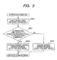
- FIG. 3 is a flowchart that most appropriately depicts the feature of the present invention and describes the processing performed in this embodiment, in which pre-heating control of the fixing device during a stand-by period (in the stand-by mode) is selected in accordance with the setup for the power-saving mode transition time period T.
- this processing is to be initiated immediately after the power switch of the laser beam printer 100 (referred to as the apparatus in FIG. 3 ) is turned on.
- the control part 118 permits the apparatus load parts to perform multiple pre-rotations.
- the process of the multiple pre-rotations is an operation performed to determine whether almost of the all load parts included in the laser beam printer 100 are operating normally.
- the warm-up process is performed for the fixing device 109 to set the laser beam printer 100 into the printing stand-by state.
- the laser beam printer 100 does not receive a print job during the multiple pre-rotations or the warm-up process at step 300, or when, in a case wherein the laser beam printer 100 received a print job and the printing for the job has been completed, the laser beam printer 100 is transited to the printing stand-by state.
- the printing stand-by state is the state in which a print job can be started within a short period of time, and generally, the laser beam printer 100 is maintained in the stand-by state. Therefore, upon receiving a print job from a user while in the stand-by state, the laser beam printer 100 can immediately perform the printing operation.
- the fixing device 109 has been pre-heated when the laser beam printer 109 is to be transited to the printing stand-by state.
- a heated roller fixing device is employed as the fixing device 109
- the fixing device 109 is pre-heated during the printing stand-by period.
- X minutes is a threshold value to use for a determination (a reference time period).
- the threshold value X is stored in the memory device 202, such as the ROM, of the control part 118, and the CPU 200 of the control part 118 performs the determination in the following manner, employing the power-saving mode transition time period T, entered at the operation panel 115, and the threshold value X.
- step S301 When the power-saving mode transition time period T is shorter than the threshold period X at step S301 (Y: step S301), program control advances to a process in which pre-heating of the fixing device 109 is not to be performed when the laser beam printer 100 is transited to the stand-by state (step S302) (in FIG. 3 , "choose power energy saving operation mode).
- the CPU 200 permits the fixing current supply circuit 201 of the power supply device 117 to turn off the fixing heater 110 of the fixing device 109, so that the process that inhibits pre-heating (in FIG. 3 , "stop pre-heat mode”) can be performed.
- a short power-saving mode transition time period T such as five minutes
- pre-heating of the fixing device 109 during the stand-by period does not fit to user's purpose, and rather becomes a defect.
- the heat capacity of the fixing device 109 is considerably greater than that of a film fixing device.
- the temperature of the fixing device 109 falls little in merely about five minutes.
- the condition is such that the fixing device 109 is not pre-heated in the stand-by state and before a transition time period of five minutes has elapsed, the user is not inconvenienced.
- step S301 when, at step S301, the power-saving mode transition time period T is set longer than the threshold period X (N: at step S301), program control is transited to the process for performing pre-heating when the apparatus is transited to the stand-by state (step S303) (in FIG. 3 , "choose normal operation mode").
- step S303 program control is transited to the process for performing pre-heating when the apparatus is transited to the stand-by state (step S303) (in FIG. 3 , "choose normal operation mode").
- start pre-heat mode When such a fixing device 109 is thereafter employed to initiate a print job, the temperature of the fixing device 109 will have dropped much and a warm-up period is so long that the user can not ignore it. Therefore, the pre-heating control ("start pre-heat mode") should be selected.
- the energy-saving operation mode (step S302) or the normal operation mode (step S303) is selected, and the stand-by mode is entered. That is, when the time period T entered using the mode transition time period setting part is shorter than the reference period X, the average electric power consumed by the fixing heater 110 in the stand-by mode is smaller than when the time period T is longer than the reference period X. In this embodiment, when the time period T set using the mode transition time period setting part is shorter than the reference period X, no electric power is consumed by the fixing heater 110 while in the stand-by mode.
- the fixing heater 110 instead of completely no power being consumed by the fixing heater 110, low power consumption by the fixing heater 110 is possible by setting the target temperature for the fixing roller in the energy-saving operation mode lower than the target temperature in the normal operation mode. Further, without providing a target temperature, a fixed supply of electric power may be supplied so that the electric power consumed by the fixing heater 110 in the energy-saving operation mode is lower than that in the normal operation mode.
- an image forming apparatus can be provided wherein the user can set up the mode transition period as preferred, and power savings can be obtained with a simple setup.
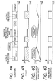
- FIGS. 4A to 4D and FIGS. 5A to 5D are diagrams for describing the relationship of the performance of the pre-heating process for the fixing device 109 in the printing stand-by state, the change in the temperature of the fixing device 109 and the warm-up period.
- the relationship in FIGS. 4A to 4D represents a case wherein the processing advances to step S302 in FIG. 3 , i.e., the laser beam printer 100 is transited to the energy-saving operation mode (the pre-heat mode is stopped).
- the relationship in FIGS. 5A to 5D represents a case wherein the processing is transited to step S303 in FIG.
- FIGS. 4A and 5A are diagrams illustrating a time-transient change in the state of the laser beam printer (apparatus) 100.
- FIGS. 4B and 5B are diagrams illustrating a time-transient change in the electric power ([W]) for the laser beam printer (apparatus) 100, the hatched portions indicate the power consumed by the fixing heater 110.
- FIGS. 4C and 5C are diagrams illustrating a time-transient change in the temperature ([°C]) of the fixing device 109.
- FIGS. 4D and 5D are diagrams illustrating a time-transient change in the pre-heat ON and OFF periods for the fixing device 109.
- the time period T is set shorter than the reference period X
- the electric power consumed by the heater in the stand-by mode is zero ( FIG. 4B ).
- the time period T is set longer than the reference period X, some electric power is consumed by the fixing heater in the stand-by state ( FIG. 5B ).
- an adjusted temperature value for the fixing device in the pre-heat mode (in FIGS. 4A to 4D and FIGS. 5A to 5D , "target-temp at stand-by") is set higher than an adjusted temperature value for the fixing device 109 during the printing operation (in FIGS. 4A to 4D and FIGS. 5A to 5D , "target-temp at print”).
- a difference in the two temperatures may be 10°C or more.
- a temperature drop time period for the fixing device 109 that was not pre-heated and a temperature rise time period for the fixing device 109 that was pre-heated, and the adjusted temperature value for the printing operation are employed to select a threshold value, which is used to determine whether pre-heating of the fixing device 109 was performed.
- step S302 the electric power consumed by the entire apparatus is reduced in the printing stand-by state (in comparison with the electric power consumed in the stand-by states in FIGS. 4B and 5B ).
- the performance of pre-heating for the fixing device 109 changes the rise in the temperature inside the image forming apparatus (hereinafter referred to as in the apparatus).
- the apparatus wherein a fan (not shown) that provides forced-air cooling, for example, is arranged in order to prevent the melting of toner powder or to maintain the rated temperature of the electronic parts, operation of the fan is not started, and more power can be saved. That is, when pre-heating of the fixing device 109 is not required, the number of forced-air cooling devices and the length of a cooling period or the number of fan rotations are reduced, and an increased reduction in power consumption obtained.
- the pre-heat OFF state wherein the energy-saving operation was performed in the stand-by state or in the pre-heat ON state and wherein the operation was performed while taking the warm-up period into account, was selected in consonance with the power-saving mode transition time period T, which was set by the user, and the pre-heat control was performed as preferred by the user.
- T the power-saving mode transition time period
- the mode of the appratus may transfer to the power-saving mode without cooling the inside of the appratus.
- the fan is enabled in stand-by mode, while it is disabled in the power-saving mode.
- the mode of the appratus is transferred to the power-saving mode after the condition of the appratus satisfies with the predetermined condition, e.g. the temperature in the apparatus is less than the predetermined temperature.
- steps S302 and S303 Since the processing from the time the power is turned on in FIG. 6 to steps S302 and S303 is the same as that in the first embodiment, no further description of this will be given. Furthermore, since the processing following step S303, at which the pre-heating process is selected, is the same as that in the first embodiment, no further description for this will be given.
- step S500 When program control advances to step S302, whereat pre-heat control is not to be performed, a check is performed to determine whether a power-saving mode transition condition, such as a temperature rise in the apparatus, has been established (step S500).
- the power-saving mode transition condition is not limited only to control of the temperature rise in the apparatus, but also includes control of the discharge of a volatile organic compound, i.e., includes all the conditions that ensure product quality is assured, without any problems being encountered when the laser beam printer 100 is transited to the power-saving mode. For example, the condition in which the predetermined temperature rise in the apparatus is satisfactory, or in which the predetermined amount of volatile organic compounds discharged is satisfactory.
- step S501 When the power-saving mode transition condition is not satisfied at step S500 (N: step S500), at step S501 a transition condition control process, such as the control process for the temperature rise in the apparatus, is performed. And when the transition condition control process, such as the temperature rise control process, is performed, the laser beam printer 100 is in the printing stand-by mode. However, when the transition condition is satisfied at step S500 (Y: step S500), the operation mode is transited to the power-saving mode (execute power-saving mode). Through the above described processing, product quality for the laser beam printer 100 is ensured, and the power consumed by the apparatus can be reduced.
- a transition condition control process such as the control process for the temperature rise in the apparatus
- the transition condition control at step S501 includes control of the temperature rise in the apparatus or control of the discharge of volatile organic compounds. Further, the control part 118 performs temperature counting to predict the temperature state, and changes the control for a fan based on the obtained temperature count value and a register counter value stored in advance (memory counter value). Then, the control part 118 performs the temperature rise control process or the volatile organic compound discharge control process. In this case, the fan is used to limit the rise in the temperature in the apparatus and to collect the volatile organic compounds. These fan control processes may be performed using a storage element or a thermoelectric transducer in order to provide greater power savings.
- FIGS. 7A to 7D are diagrams for describing the relationship of a pre-heat threshold value of the fixing device 109, the temperature change in the fixing device 109 and the warm-up period.
- FIG. 7A is a diagram illustrating a time-transient change in the state of the laser beam printer (apparatus) 100.
- FIG. 7B is a diagram illustrating a time-transient change in the electric power ([W]) consumed by the laser beam printer (apparatus) 100.
- FIG. 7C is a diagram illustrating a time-transient change in the temperature ([°C]) of the fixing device 109.
- FIG. 7D is a diagram illustrating a time-transient change in the pre-heat ON and OFF states of the fixing device 109.
- the stand-by period can be minimized, as illustrated in FIG. 7A .
- the apparatus power consumption can be reduced.
Landscapes
- Physics & Mathematics (AREA)
- General Physics & Mathematics (AREA)
- Engineering & Computer Science (AREA)
- Microelectronics & Electronic Packaging (AREA)
- Fixing For Electrophotography (AREA)
- Control Or Security For Electrophotography (AREA)
- Accessory Devices And Overall Control Thereof (AREA)
Claims (3)
- Bilderzeugungsvorrichtung (100), umfassend:eine Bilderzeugungseinrichtung, die ausgelegt ist, ein Bild auf einem Aufzeichnungsmaterial zu erzeugen;eine Fixiereinrichtung (109), die eine zum Erzeugen von Wärme aus elektrischer Energie konfigurierte Wärmequelle (110) umfasst, konfiguriert zum Fixieren des auf dem Aufzeichnungsmaterial erzeugten Bilds; undeine Steuereinrichtung (118), die konfiguriert ist, den Betrieb der Fixiereinrichtung zu steuern,wobei die Bilderzeugungsvorrichtung betreibbar ist, von einem Standby-Modus in einen Stromsparmodus zu wechseln, in welchem die durch die Bilderzeugungsvorrichtung verbrauchte elektrische Leistung weniger ist als die durch die Bilderzeugungsvorrichtung verbrauchte elektrische Leistung im Standby-Modus, falls die Bilderzeugungsvorrichtung im Standby-Modus innerhalb eines bestimmten Zeitraums keinen Druckauftrag erhält, und die Bilderzeugungsvorrichtung ferner umfasst:eine Zeitraumeinstellungseinrichtung (115, 118), die konfiguriert ist, einem Benutzer das Festlegen eines Zeitraums (T) zum Wechseln in den Stromsparmodus zu gestatten,dadurch gekennzeichnet, dassdie Steuereinrichtung (118) konfiguriert ist, die Wärmequelle (110) so zu steuern, dass sie im Standby-Modus Vorwärmen der Fixiereinrichtung (109) durchführt,wobei die Steuereinrichtung (118) konfiguriert ist, die Wärmequelle (110) so zu steuern, dass sie Vorwärmen der Fixiereinrichtung (109) nicht durchführt, wenn der eingestellte Zeitraum (T) kürzer ist als ein Vergleichszeitraum (X), sodass die durchschnittlich im Standby-Modus verbrauchte elektrische Leistung kleiner ist als die durchschnittlich im Standby-Modus verbrauchte elektrische Leistung, wenn der durch den Benutzer festgelegte Zeitraum länger ist als der Vergleichszeitraum.
- Bilderzeugungsvorrichtung nach Anspruch 1, wobei die Wärmequelle ausgelegt ist, im Standby-Modus keine elektrische Leistung zu verbrauchen, wenn der unter Verwendung der Zeitraumeinstellungseinrichtung eingestellte Zeitraum kürzer ist als der Vergleichszeitraum.
- Verfahren des Reduzierens der durch eine Bilderzeugungsvorrichtung (100) verbrauchten elektrischen Leistung, wobei die Bilderzeugungsvorrichtung umfasst:eine Bilderzeugungseinrichtung, die ausgelegt ist, ein Bild auf einem Aufzeichnungsmaterial zu erzeugen;eine Fixiereinrichtung (109), die eine zum Erzeugen von Wärme aus elektrischer Energie konfigurierte Wärmequelle (110) umfasst, zum Fixieren des auf dem Aufzeichnungsmaterial erzeugten Bilds;eine Steuereinrichtung (118), die konfiguriert ist, den Betrieb der Fixiereinrichtung zu steuern, undeine durch einen Benutzer bedienbare Zeitraumeinstellungseinrichtung (115, 118);wobei das Verfahren umfasst:Wechseln der Bilderzeugungsvorrichtung von einem Standby-Modus in einen Stromsparmodus, in dem die durch die Bilderzeugungsvorrichtung verbrauchte elektrische Leistung weniger ist als die durch die Bilderzeugungsvorrichtung verbrauchte elektrische Leistung im Standby-Modus, wenn die Bilderzeugungsvorrichtung im Standby-Modus innerhalb eines bestimmten Zeitraums keinen Druckauftrag erhält, und die Bilderzeugungsvorrichtung ferner umfasst:Einstellen eines Zeitraums zum Wechseln in den Stromsparmodus, gekennzeichnet durchDurchführen von Vorwärmen der Fixiereinrichtung (109) im Standby-Modus,wobei der Vorwärmschritt nicht durchgeführt wird, wenn der eingestellte Zeitraum kürzer ist als ein Vergleichszeitraum, sodass die durchschnittlich im Standby-Modus verbrauchte elektrische Leistung kleiner ist als die durchschnittlich im Standby-Modus verbrauchte elektrische Leistung, wenn der durch den Benutzer festgelegte Zeitraum länger ist als der Vergleichszeitraum.
Applications Claiming Priority (1)
| Application Number | Priority Date | Filing Date | Title |
|---|---|---|---|
| JP2007123221A JP5058669B2 (ja) | 2007-05-08 | 2007-05-08 | 画像形成装置 |
Publications (3)
| Publication Number | Publication Date |
|---|---|
| EP1990685A2 EP1990685A2 (de) | 2008-11-12 |
| EP1990685A3 EP1990685A3 (de) | 2013-06-26 |
| EP1990685B1 true EP1990685B1 (de) | 2018-12-19 |
Family
ID=39673478
Family Applications (1)
| Application Number | Title | Priority Date | Filing Date |
|---|---|---|---|
| EP08155912.2A Ceased EP1990685B1 (de) | 2007-05-08 | 2008-05-08 | Bilderzeugungsvorrichtung |
Country Status (3)
| Country | Link |
|---|---|
| US (2) | US8032048B2 (de) |
| EP (1) | EP1990685B1 (de) |
| JP (1) | JP5058669B2 (de) |
Families Citing this family (21)
| Publication number | Priority date | Publication date | Assignee | Title |
|---|---|---|---|---|
| US10549157B2 (en) | 2007-03-30 | 2020-02-04 | Acushnet Company | Buoyant, high coefficient of restitution (CoR) golf ball having a reduced flight distance yet the perceived flight trajectory of regular distance high CoR golf balls |
| US10668328B2 (en) | 2013-01-09 | 2020-06-02 | Acushnet Company | Golf ball having a hollow center |
| US11684824B2 (en) | 2007-03-30 | 2023-06-27 | Acushnet Company | Buoyant high coefficient of restitution (CoR) golf ball incorporating aerodynamics targeting flight trajectory |
| JP5058669B2 (ja) * | 2007-05-08 | 2012-10-24 | キヤノン株式会社 | 画像形成装置 |
| KR101558270B1 (ko) | 2009-01-06 | 2015-10-08 | 삼성전자주식회사 | 화상형성장치 및 그 소비 전력 제어 방법 |
| JP4810590B2 (ja) * | 2009-05-28 | 2011-11-09 | シャープ株式会社 | 定着装置、画像形成装置、定着装置の制御方法、制御プログラムおよびその記録媒体 |
| JP5312218B2 (ja) * | 2009-06-17 | 2013-10-09 | キヤノン株式会社 | 画像形成装置、画像形成装置の制御方法、及びプログラム |
| JP5451202B2 (ja) * | 2009-06-18 | 2014-03-26 | キヤノン株式会社 | 画像形成装置及びその制御方法、並びにプログラム |
| CN102862381B (zh) * | 2009-09-15 | 2015-11-18 | 株式会社东芝 | 脱色装置 |
| JP5119294B2 (ja) * | 2010-06-01 | 2013-01-16 | 株式会社沖データ | 画像形成装置及び画像形成システム |
| US20120069368A1 (en) * | 2010-09-20 | 2012-03-22 | Toshiba Tec Kabushiki Kaisha | Image forming apparatus, and power-saving mode setting method of the image forming apparatus |
| JP5429149B2 (ja) | 2010-12-15 | 2014-02-26 | コニカミノルタ株式会社 | 画像形成装置および定着装置の温度制御方法 |
| JP5865096B2 (ja) * | 2011-06-16 | 2016-02-17 | キヤノン株式会社 | 画像形成装置及びその制御方法、並びにプログラム |
| JP5963105B2 (ja) | 2012-02-02 | 2016-08-03 | 株式会社リコー | 定着装置及び画像形成装置 |
| JP5995524B2 (ja) * | 2012-05-23 | 2016-09-21 | キヤノン株式会社 | 情報処理装置、情報処理装置の制御方法、プログラム、および記録媒体 |
| JP5983174B2 (ja) * | 2012-08-15 | 2016-08-31 | 富士ゼロックス株式会社 | 画像処理装置、処理時間シミュレーション装置、処理時間シミュレーションプログラム |
| US10427006B2 (en) | 2013-12-31 | 2019-10-01 | Acushnet Company | Golf ball incorporating at least one layer of plasticized neutralized acid polymer composition containing low molecular weight acid wax(es) as sole acid polymer component and low molecular weight non-acid wax(es) in the non-acid polymer component |
| US10105576B2 (en) | 2013-12-31 | 2018-10-23 | Acushnet Company | Golf ball incorporating at least one layer of plasticized neutralized acid polymer composition containing low molecular weight acid wax(es) as sole acid polymer component and method of making |
| US10441849B2 (en) | 2013-12-31 | 2019-10-15 | Acushnet Company | Golf ball incorporating at least one layer of neutralized acid polymer composition containing low molecular weight acid wax(es) as sole acid polymer component and low molecular weight non-acid wax(es) in the non-acid polymer component |
| US10105575B2 (en) | 2013-12-31 | 2018-10-23 | Acushnet Company | Golf ball incorporating at least one layer of neutralized acid polymer composition containing low molecular weight acid wax(es) as sole acid polymer component and method of making |
| JP2025109300A (ja) * | 2024-01-12 | 2025-07-25 | ブラザー工業株式会社 | 画像形成装置 |
Family Cites Families (17)
| Publication number | Priority date | Publication date | Assignee | Title |
|---|---|---|---|---|
| JPH04282653A (ja) * | 1991-03-12 | 1992-10-07 | Casio Electron Mfg Co Ltd | 画像形成装置 |
| JPH05281816A (ja) * | 1992-04-01 | 1993-10-29 | Murata Mach Ltd | 画像形成装置 |
| JPH05323710A (ja) | 1992-05-26 | 1993-12-07 | Ricoh Co Ltd | 画像形成装置 |
| JP2000131997A (ja) * | 1998-10-28 | 2000-05-12 | Casio Electronics Co Ltd | 画像形成装置 |
| JP4303893B2 (ja) * | 2001-03-14 | 2009-07-29 | 株式会社リコー | 画像出力装置 |
| JP2002296952A (ja) * | 2001-03-29 | 2002-10-09 | Ricoh Co Ltd | 電子写真装置の定着温度制御装置およびその制御方法 |
| JP3666656B2 (ja) * | 2001-11-28 | 2005-06-29 | 京セラミタ株式会社 | 複合装置 |
| JP2004101919A (ja) * | 2002-09-10 | 2004-04-02 | Ricoh Co Ltd | 省エネルギ設定方法及び画像形成装置 |
| JP4080385B2 (ja) * | 2003-06-30 | 2008-04-23 | 株式会社リコー | 画像形成装置、給電制御方法、コンピュータプログラムおよび記録媒体 |
| JP2005031380A (ja) * | 2003-07-11 | 2005-02-03 | Ricoh Co Ltd | 画像形成装置 |
| JP2005148273A (ja) * | 2003-11-13 | 2005-06-09 | Ricoh Co Ltd | 画像形成装置 |
| JP2005345894A (ja) * | 2004-06-04 | 2005-12-15 | Canon Inc | 画像形成装置 |
| JP2006023617A (ja) * | 2004-07-09 | 2006-01-26 | Ricoh Co Ltd | 画像形成装置 |
| JP2006171481A (ja) * | 2004-12-17 | 2006-06-29 | Ricoh Co Ltd | 画像形成装置 |
| JP4337780B2 (ja) * | 2005-06-27 | 2009-09-30 | ブラザー工業株式会社 | 画像形成装置 |
| JP2008064984A (ja) * | 2006-09-06 | 2008-03-21 | Kyocera Mita Corp | 画像形成装置 |
| JP5058669B2 (ja) * | 2007-05-08 | 2012-10-24 | キヤノン株式会社 | 画像形成装置 |
-
2007
- 2007-05-08 JP JP2007123221A patent/JP5058669B2/ja not_active Expired - Fee Related
-
2008
- 2008-05-02 US US12/114,243 patent/US8032048B2/en not_active Expired - Fee Related
- 2008-05-08 EP EP08155912.2A patent/EP1990685B1/de not_active Ceased
-
2011
- 2011-08-24 US US13/216,322 patent/US8265508B2/en active Active
Non-Patent Citations (1)
| Title |
|---|
| None * |
Also Published As
| Publication number | Publication date |
|---|---|
| US20080279578A1 (en) | 2008-11-13 |
| JP2008281607A (ja) | 2008-11-20 |
| JP5058669B2 (ja) | 2012-10-24 |
| EP1990685A3 (de) | 2013-06-26 |
| US8032048B2 (en) | 2011-10-04 |
| EP1990685A2 (de) | 2008-11-12 |
| US20110311258A1 (en) | 2011-12-22 |
| US8265508B2 (en) | 2012-09-11 |
Similar Documents
| Publication | Publication Date | Title |
|---|---|---|
| EP1990685B1 (de) | Bilderzeugungsvorrichtung | |
| EP1562082B1 (de) | Bilderzeugungsgerät mit Fixieranlage und Detektion der Kapazitätsleistung | |
| US7020403B2 (en) | Image forming apparatus achieving reduction in power consumption | |
| US8351801B2 (en) | Image forming apparatus with a determining section that makes a determination when the apparatus transitions to a power saving mode of whether an image can be formed | |
| GB2282991A (en) | Energy-saving image forming apparatus | |
| JP5327510B2 (ja) | 画像形成装置 | |
| JP2012128189A (ja) | 画像形成装置および定着装置の温度制御方法 | |
| JP4388876B2 (ja) | 画像形成装置 | |
| JP2000330426A (ja) | 電子写真装置 | |
| JP2008262295A (ja) | 画像形成システム | |
| JP2011141437A (ja) | 画像形成装置 | |
| JP4491504B2 (ja) | 画像形成装置 | |
| JPH10268713A (ja) | 自動電源オフ回路 | |
| JP2012118228A (ja) | 画像形成装置 | |
| JP4956169B2 (ja) | 画像形成装置 | |
| JP2004294779A (ja) | 定着装置及び画像形成装置 | |
| JP7506015B2 (ja) | 画像形成装置 | |
| JP4458867B2 (ja) | 画像形成装置 | |
| JP4666611B2 (ja) | 充電システム、及び蓄電サーバ | |
| JP4421529B2 (ja) | 画像形成装置 | |
| JP7468147B2 (ja) | 画像形成装置 | |
| JP2010122448A (ja) | 画像形成装置 | |
| JP2006142768A (ja) | 画像形成装置 | |
| JP2002356039A (ja) | 画像形成装置 | |
| JP2005241660A (ja) | 画像形成装置 |
Legal Events
| Date | Code | Title | Description |
|---|---|---|---|
| PUAI | Public reference made under article 153(3) epc to a published international application that has entered the european phase |
Free format text: ORIGINAL CODE: 0009012 |
|
| AK | Designated contracting states |
Kind code of ref document: A2 Designated state(s): AT BE BG CH CY CZ DE DK EE ES FI FR GB GR HR HU IE IS IT LI LT LU LV MC MT NL NO PL PT RO SE SI SK TR |
|
| AX | Request for extension of the european patent |
Extension state: AL BA MK RS |
|
| PUAL | Search report despatched |
Free format text: ORIGINAL CODE: 0009013 |
|
| AK | Designated contracting states |
Kind code of ref document: A3 Designated state(s): AT BE BG CH CY CZ DE DK EE ES FI FR GB GR HR HU IE IS IT LI LT LU LV MC MT NL NO PL PT RO SE SI SK TR |
|
| AX | Request for extension of the european patent |
Extension state: AL BA MK RS |
|
| RIC1 | Information provided on ipc code assigned before grant |
Ipc: G03G 15/00 20060101AFI20130521BHEP Ipc: G03G 15/20 20060101ALI20130521BHEP |
|
| 17P | Request for examination filed |
Effective date: 20140102 |
|
| RBV | Designated contracting states (corrected) |
Designated state(s): AT BE BG CH CY CZ DE DK EE ES FI FR GB GR HR HU IE IS IT LI LT LU LV MC MT NL NO PL PT RO SE SI SK TR |
|
| AKX | Designation fees paid |
Designated state(s): DE FR GB |
|
| 17Q | First examination report despatched |
Effective date: 20171123 |
|
| GRAP | Despatch of communication of intention to grant a patent |
Free format text: ORIGINAL CODE: EPIDOSNIGR1 |
|
| INTG | Intention to grant announced |
Effective date: 20180522 |
|
| RIN1 | Information on inventor provided before grant (corrected) |
Inventor name: MONDE, MASAFUMI |
|
| GRAS | Grant fee paid |
Free format text: ORIGINAL CODE: EPIDOSNIGR3 |
|
| GRAJ | Information related to disapproval of communication of intention to grant by the applicant or resumption of examination proceedings by the epo deleted |
Free format text: ORIGINAL CODE: EPIDOSDIGR1 |
|
| GRAL | Information related to payment of fee for publishing/printing deleted |
Free format text: ORIGINAL CODE: EPIDOSDIGR3 |
|
| GRAR | Information related to intention to grant a patent recorded |
Free format text: ORIGINAL CODE: EPIDOSNIGR71 |
|
| INTC | Intention to grant announced (deleted) | ||
| GRAA | (expected) grant |
Free format text: ORIGINAL CODE: 0009210 |
|
| INTG | Intention to grant announced |
Effective date: 20181106 |
|
| AK | Designated contracting states |
Kind code of ref document: B1 Designated state(s): DE FR GB |
|
| REG | Reference to a national code |
Ref country code: GB Ref legal event code: FG4D |
|
| REG | Reference to a national code |
Ref country code: DE Ref legal event code: R096 Ref document number: 602008058368 Country of ref document: DE |
|
| REG | Reference to a national code |
Ref country code: DE Ref legal event code: R097 Ref document number: 602008058368 Country of ref document: DE |
|
| PLBE | No opposition filed within time limit |
Free format text: ORIGINAL CODE: 0009261 |
|
| STAA | Information on the status of an ep patent application or granted ep patent |
Free format text: STATUS: NO OPPOSITION FILED WITHIN TIME LIMIT |
|
| 26N | No opposition filed |
Effective date: 20190920 |
|
| PG25 | Lapsed in a contracting state [announced via postgrant information from national office to epo] |
Ref country code: FR Free format text: LAPSE BECAUSE OF NON-PAYMENT OF DUE FEES Effective date: 20190531 |
|
| PGFP | Annual fee paid to national office [announced via postgrant information from national office to epo] |
Ref country code: GB Payment date: 20240419 Year of fee payment: 17 |
|
| PGFP | Annual fee paid to national office [announced via postgrant information from national office to epo] |
Ref country code: DE Payment date: 20240418 Year of fee payment: 17 |
|
| REG | Reference to a national code |
Ref country code: DE Ref legal event code: R119 Ref document number: 602008058368 Country of ref document: DE |
|
| GBPC | Gb: european patent ceased through non-payment of renewal fee |
Effective date: 20250508 |
|
| PG25 | Lapsed in a contracting state [announced via postgrant information from national office to epo] |
Ref country code: GB Free format text: LAPSE BECAUSE OF NON-PAYMENT OF DUE FEES Effective date: 20250508 |
|
| PG25 | Lapsed in a contracting state [announced via postgrant information from national office to epo] |
Ref country code: DE Free format text: LAPSE BECAUSE OF NON-PAYMENT OF DUE FEES Effective date: 20251202 |