EP1990813A1 - Verfahren und Gerät zur Reduzierung der Nachschwingungen in einer Zündspule zur Ionenabfühlverarbeitung - Google Patents
Verfahren und Gerät zur Reduzierung der Nachschwingungen in einer Zündspule zur Ionenabfühlverarbeitung Download PDFInfo
- Publication number
- EP1990813A1 EP1990813A1 EP08155528A EP08155528A EP1990813A1 EP 1990813 A1 EP1990813 A1 EP 1990813A1 EP 08155528 A EP08155528 A EP 08155528A EP 08155528 A EP08155528 A EP 08155528A EP 1990813 A1 EP1990813 A1 EP 1990813A1
- Authority
- EP
- European Patent Office
- Prior art keywords
- winding
- ignition apparatus
- primary
- control
- resistor
- Prior art date
- Legal status (The legal status is an assumption and is not a legal conclusion. Google has not performed a legal analysis and makes no representation as to the accuracy of the status listed.)
- Granted
Links
- 238000000034 method Methods 0.000 title description 3
- 238000012545 processing Methods 0.000 title description 3
- 238000004804 winding Methods 0.000 claims abstract description 161
- 239000000463 material Substances 0.000 claims description 17
- 230000001629 suppression Effects 0.000 claims description 9
- 230000007246 mechanism Effects 0.000 claims description 8
- 238000001514 detection method Methods 0.000 claims description 5
- 230000003247 decreasing effect Effects 0.000 claims description 4
- 230000004044 response Effects 0.000 claims description 4
- XUIMIQQOPSSXEZ-UHFFFAOYSA-N Silicon Chemical compound [Si] XUIMIQQOPSSXEZ-UHFFFAOYSA-N 0.000 claims description 2
- 229910052710 silicon Inorganic materials 0.000 claims description 2
- 239000010703 silicon Substances 0.000 claims description 2
- 230000004907 flux Effects 0.000 abstract description 3
- 230000002441 reversible effect Effects 0.000 abstract description 2
- 150000002500 ions Chemical class 0.000 description 21
- 238000002485 combustion reaction Methods 0.000 description 10
- 238000010586 diagram Methods 0.000 description 10
- 238000004382 potting Methods 0.000 description 10
- 230000006870 function Effects 0.000 description 8
- 239000004593 Epoxy Substances 0.000 description 6
- 230000003071 parasitic effect Effects 0.000 description 6
- 230000000903 blocking effect Effects 0.000 description 4
- 239000008393 encapsulating agent Substances 0.000 description 4
- 230000000670 limiting effect Effects 0.000 description 4
- 238000013459 approach Methods 0.000 description 3
- 230000007423 decrease Effects 0.000 description 3
- 230000000694 effects Effects 0.000 description 3
- 230000001965 increasing effect Effects 0.000 description 3
- 239000011810 insulating material Substances 0.000 description 3
- 238000005259 measurement Methods 0.000 description 3
- 229920001707 polybutylene terephthalate Polymers 0.000 description 3
- XEEYBQQBJWHFJM-UHFFFAOYSA-N Iron Chemical compound [Fe] XEEYBQQBJWHFJM-UHFFFAOYSA-N 0.000 description 2
- 230000008901 benefit Effects 0.000 description 2
- 238000011217 control strategy Methods 0.000 description 2
- 239000002184 metal Substances 0.000 description 2
- 229910052751 metal Inorganic materials 0.000 description 2
- 229920000728 polyester Polymers 0.000 description 2
- 230000000750 progressive effect Effects 0.000 description 2
- 230000002829 reductive effect Effects 0.000 description 2
- 229920001169 thermoplastic Polymers 0.000 description 2
- 239000004416 thermosoftening plastic Substances 0.000 description 2
- 229910000976 Electrical steel Inorganic materials 0.000 description 1
- 239000004727 Noryl Substances 0.000 description 1
- 229920001207 Noryl Polymers 0.000 description 1
- 239000004721 Polyphenylene oxide Substances 0.000 description 1
- 230000004323 axial length Effects 0.000 description 1
- 230000004888 barrier function Effects 0.000 description 1
- 230000015556 catabolic process Effects 0.000 description 1
- 230000008859 change Effects 0.000 description 1
- 230000006835 compression Effects 0.000 description 1
- 238000007906 compression Methods 0.000 description 1
- 239000004020 conductor Substances 0.000 description 1
- 238000010276 construction Methods 0.000 description 1
- 230000008878 coupling Effects 0.000 description 1
- 238000010168 coupling process Methods 0.000 description 1
- 238000005859 coupling reaction Methods 0.000 description 1
- 238000007599 discharging Methods 0.000 description 1
- 238000010292 electrical insulation Methods 0.000 description 1
- 230000007613 environmental effect Effects 0.000 description 1
- 239000000446 fuel Substances 0.000 description 1
- 230000001939 inductive effect Effects 0.000 description 1
- 238000009434 installation Methods 0.000 description 1
- 238000009413 insulation Methods 0.000 description 1
- 229910052742 iron Inorganic materials 0.000 description 1
- 239000000696 magnetic material Substances 0.000 description 1
- 239000000203 mixture Substances 0.000 description 1
- 238000012986 modification Methods 0.000 description 1
- 230000004048 modification Effects 0.000 description 1
- 239000002245 particle Substances 0.000 description 1
- 239000004033 plastic Substances 0.000 description 1
- -1 polybutylene terephthalate Polymers 0.000 description 1
- 230000001681 protective effect Effects 0.000 description 1
- 238000000926 separation method Methods 0.000 description 1
- 230000007704 transition Effects 0.000 description 1
Images



Classifications
-
- H—ELECTRICITY
- H01—ELECTRIC ELEMENTS
- H01F—MAGNETS; INDUCTANCES; TRANSFORMERS; SELECTION OF MATERIALS FOR THEIR MAGNETIC PROPERTIES
- H01F38/00—Adaptations of transformers or inductances for specific applications or functions
- H01F38/12—Ignition, e.g. for IC engines
-
- F—MECHANICAL ENGINEERING; LIGHTING; HEATING; WEAPONS; BLASTING
- F02—COMBUSTION ENGINES; HOT-GAS OR COMBUSTION-PRODUCT ENGINE PLANTS
- F02P—IGNITION, OTHER THAN COMPRESSION IGNITION, FOR INTERNAL-COMBUSTION ENGINES; TESTING OF IGNITION TIMING IN COMPRESSION-IGNITION ENGINES
- F02P3/00—Other installations
- F02P3/02—Other installations having inductive energy storage, e.g. arrangements of induction coils
- F02P3/04—Layout of circuits
- F02P3/055—Layout of circuits with protective means to prevent damage to the circuit, e.g. semiconductor devices or the ignition coil
-
- H—ELECTRICITY
- H01—ELECTRIC ELEMENTS
- H01F—MAGNETS; INDUCTANCES; TRANSFORMERS; SELECTION OF MATERIALS FOR THEIR MAGNETIC PROPERTIES
- H01F27/00—Details of transformers or inductances, in general
- H01F27/34—Special means for preventing or reducing unwanted electric or magnetic effects, e.g. no-load losses, reactive currents, harmonics, oscillations, leakage fields
- H01F27/343—Preventing or reducing surge voltages; oscillations
- H01F27/345—Preventing or reducing surge voltages; oscillations using auxiliary conductors
-
- H—ELECTRICITY
- H01—ELECTRIC ELEMENTS
- H01F—MAGNETS; INDUCTANCES; TRANSFORMERS; SELECTION OF MATERIALS FOR THEIR MAGNETIC PROPERTIES
- H01F27/00—Details of transformers or inductances, in general
- H01F27/40—Structural association with built-in electric component, e.g. fuse
-
- F—MECHANICAL ENGINEERING; LIGHTING; HEATING; WEAPONS; BLASTING
- F02—COMBUSTION ENGINES; HOT-GAS OR COMBUSTION-PRODUCT ENGINE PLANTS
- F02P—IGNITION, OTHER THAN COMPRESSION IGNITION, FOR INTERNAL-COMBUSTION ENGINES; TESTING OF IGNITION TIMING IN COMPRESSION-IGNITION ENGINES
- F02P17/00—Testing of ignition installations, e.g. in combination with adjusting; Testing of ignition timing in compression-ignition engines
- F02P17/12—Testing characteristics of the spark, ignition voltage or current
-
- F—MECHANICAL ENGINEERING; LIGHTING; HEATING; WEAPONS; BLASTING
- F02—COMBUSTION ENGINES; HOT-GAS OR COMBUSTION-PRODUCT ENGINE PLANTS
- F02P—IGNITION, OTHER THAN COMPRESSION IGNITION, FOR INTERNAL-COMBUSTION ENGINES; TESTING OF IGNITION TIMING IN COMPRESSION-IGNITION ENGINES
- F02P17/00—Testing of ignition installations, e.g. in combination with adjusting; Testing of ignition timing in compression-ignition engines
- F02P17/12—Testing characteristics of the spark, ignition voltage or current
- F02P2017/125—Measuring ionisation of combustion gas, e.g. by using ignition circuits
Definitions
- the present invention relates generally to ignition coils, and more particularly, to a method and apparatus to reduce ring out in an ignition coil to more effectively allow for ion sense processing.
- Modem inductive-type automotive ignition systems commonly utilize power switching devices to control the flow of primary, charging current through the coil. Due to the inductive nature of an ignition coil, they exhibit a natural ringing of the secondary, high voltage after a spark has been extinguished ("end-of-spark ringing").
- ion current is indicative of the quantity of the combustion event, or whether in fact combustion has occurred at all (e.g., a misfire condition).
- An AC level of the ion current may also be used to determine whether knock exists.
- any sensing of the ion current that is done after the spark needs to timed so as to allow for the end-of-spark ringing to subside through natural decay.
- the decay characteristics of the end-of-spark secondary voltage ring out are determined in part by the existent electrical charge as well as the inherent losses in the magnetic circuit, for example, the amount of core losses in the central magnetic core of the ignition coil ("eddy current losses").
- eddy current losses the amount of core losses in the central magnetic core of the ignition coil.
- the present invention provides a structure for simulating magnetic circuit losses in the ignition coil in order to limit the secondary voltage ringing at the end of discharge without causing an excessive parasitic load that would otherwise unacceptably reduce the output.
- An ignition apparatus in accordance with the present invention includes a central core having a longitudinal axis, primary and secondary windings, and a shield.
- the core and primary and secondary windings are included in a magnetic circuit.
- the apparatus includes a suppression mechanism operatively coupled to the magnetic circuit configured to suppress ringing in the secondary voltage after a spark event.
- the suppression mechanism includes a control winding disposed in the magnetic circuit.
- the control winding has a pair of terminals across which a circuit element is disposed.
- the circuit element comprises either a diode or a shunt resistor, respectively.
- the primary winding is disposed radially-outwardly of the central core in a first winding orientation while the secondary winding is wound radially-outwardly of the primary winding and includes a high-voltage end configured for connection to a spark plug.
- the control winding is wound in a second winding orientation wherein the first winding orientation and the second winding orientation are the same.
- the diode has an anode terminal and a cathode terminal coupled to the pair of terminals of the control winding such that (i) the diode is forward-biased when a secondary voltage across the secondary winding is positive, and (ii) the diode is reverse-biased when the secondary voltage is negative.
- the shunt resistor is selectively connected across the control winding using a controlled switch.
- a shunt resistor is connected across the primary winding, or, is selectively connected across the primary winding through a control circuit and an SCR.
- An ignition system including an ion sense detection system is also presented.
- FIG. 1 shows an environment in which an ignition apparatus 10, controlled by a control unit 11 or the like, may be employed.
- Apparatus 10 is adapted for installation to a conventional internal combustion engine 12 by way of a spark plug 13 (best shown in Figure 9 ) in threaded engagement with a spark plug opening 14 into a combustion cylinder.
- overall spark timing (dwell control) and the like is provided by control unit 11.
- one ignition apparatus is provided per spark plug.
- either the ignition apparatus 10 or the control unit 11 include ion current sensing capability, as known in the art.
- the present invention is configured to provide a structure for simulating magnetic circuit losses (e.g. , such as core losses) in ignition apparatus 10 to limit the ringing at the end of spark discharge, without causing at the same time an excessive parasitic load that would reduce the overall output of the ignition apparatus 10 ( e.g. , measured in energy).
- magnetic circuit losses e.g. , such as core losses
- FIG. 2A shows an electronic spark timing (EST) signal as a timing reference with respect to Figures 2B - 2C .
- the EST signal as known in the art, controls the flow of primary current through the primary winding of ignition apparatus 10.
- Figure 2B shows the primary current increasing from zero in timed relation with the assertion of the EST signal. This is the well-known charging phase of the ignition apparatus.
- Figure 2C shows the secondary voltage established across the secondary winding, in timed relation to the EST signal.
- the EST signal is asserted, typically, the automotive vehicle battery voltage B+ is applied across the primary winding, due to grounding one end (the low voltage end) of the primary winding via a switch closure. This battery voltage B+ also appears across the secondary winding, as shown.
- the switch is opened, interrupting the primary current ( Figure 2B ). This results in a large, spark voltage being established across the secondary winding, as known. This is also shown in Figure 2C as a large, negative polarity spike (not to scale). After the spark discharge event has concluded, as indicated generally when the negative polarity secondary voltage first returns to cross the zero voltage level ("zero crossing"), an interval of "ringing" thereafter typically occurs, and which is designated interval 15 in Figure 2C .
- the present invention is adapted to reduce such ringing to acceptable levels by simulating magnetic circuit losses to hasten the decay of any residual electrical charge.
- a number of embodiments will be disclosed, each providing an effective suppression mechanism operatively coupled to the magnetic circuit configured to suppress ringing in the output secondary voltage after a spark event.
- a control winding and a diode are used to selectively establish such losses.
- the control winding and diode cooperate to bleed, effectively, residual electrical charge in order to limit the ringing.
- such diode is oriented so that it is forward-biased only during the time when the secondary current is in a direction opposite the direction of current flow that occurs during the spark event.
- such diode is forward-biased during the time intervals designated 17. In this manner, the arrangement will not conduct during the spark event, and thus will not affect the open circuit voltage capability of the ignition apparatus 10 or the energy delivered during the spark event. There will be, however, an incremental, parasitic loss during charging of the ignition apparatus that will increase the amount of input energy required.
- FIG 3 is a simplified schematic and diagrammatic diagram of a first embodiment of the present invention, incorporating a control winding and a diode.
- Apparatus 10 includes a core 16, a primary winding 24, and a secondary winding 30. Additionally, apparatus 10 includes an outer magnetic core or shield 36 (best shown in Figure 9 ). As appreciated in the art, a magnetic flux circuit (“magnetic circuit”) is thus formed and includes at least the core 16, the primary winding 24, the secondary winding 30 and the shield 36.
- control unit 11 may itself include a control unit 70 and a switch 72. It should be understood that there are known implementations of an ignition apparatus where the primary current switch is co-located with the main ignition body and further known to dispose the switch apart from the main ignition body. Likewise, the programmed control strategies in control unit 11 may be in an independent module, in the main ignition body, or various functions thereof may be split.
- Control unit 70 is configured generally to perform a plurality of functions, including generation of an ignition control signal EST (electronic spark timing). It should be understood that the ignition control signal EST may be generated or initiated by other control units not shown, such as a powertrain control module (PCM) in accordance with known ignition control strategies, and provided to control unit 70, such that control unit 70 responds by driving switch 72 to closure in response thereto.
- the control unit 70 may include, for example, a central processing unit (CPU), memory, and input/output, all operating according to preprogrammed strategies. The strategies enable control unit 70 to perform various functions described herein. As known, the ignition control signal defines the initial charging time (e.g. , duration), and the relative timing (e.g.
- Switch 72 is configured to selectively connect primary winding 24 to ground, responsive to the ignition control signal (EST signal). Such a connection to ground, as is known generally in the art, will cause a primary current Ip to flow through primary winding 24.
- Switch 72 is illustrated in the Figures as a block diagram; however, it should be understood that switch 72 may comprise conventional components known to those of ordinary skill in the art, such as, for purposes of example only, an insulated gate bipolar transistor (IGBT).
- IGBT insulated gate bipolar transistor
- primary winding 24 is wound in a first orientation (e.g. , either clockwise (CW) or counter-clockwise (CCW)), and is marked with the well-known dot convention.
- the secondary winding 30 is wound, as also shown by the dot convention, in an orientation such that when the positive battery voltage B+ is applied across the primary winding 24, a positive voltage will be induced across the secondary winding 30 at the dot.
- the secondary circuit may also include an ion sense detection system 73 which includes a blocking diode 74 coupled to the low voltage end of secondary winding 30 and a bias and measurement circuit 75.
- Circuit 75 is configured to provide a bias voltage across the spark gap, while the measurement function is configured to measure the resulting ion current and produce a signal indicative thereof (designated V ION ).
- Plug 13 includes spaced electrodes 13a, 13b to define a spark gap 13c thereacross. It is across this gap 13c via electrodes 13a, 13b that an ion current is developed and measured to produce an ion current signal.
- Blocking diode 74 in the secondary circuit allows spark current to flow from ground across the spark gap 13c, through the secondary winding 30 and through diode 74 back to ground. However, the blocking diode 74 prevents inadvertent spark-on-make (e.g. , when EST is asserted), as described elsewhere in the art. As mentioned above, at the end of the spark discharge, ordinarily, there remains some residual electrical charge that causes a natural ringing in the secondary voltage. According to the invention, however, a control structure including a control winding 76, and a circuit element 78 such as a diode 80 are configured to simulate magnetic circuit losses such as core losses without adding a parasitic load during the spark event.
- Control winding 76 includes a pair of connection terminals and is wound in a second orientation, which, as shown, may be the same orientation as the primary winding 24.
- the control winding 76 may comprise the same type and kind of wire, namely, magnet wire, as used for the primary winding, and additionally also be wound on the central core 16 just as the primary winding 24.
- the control winding 76 may be one (1) to five (5) turns of 20-23 AWG insulated magnet wire.
- the control winding 76 may be axially offset from the primary winding 24.
- the control winding 76 is preferably included in the magnetic circuit, as defined above, so as to be coupled with and configured to facilitate the dissipation of residual electrical charge.
- Diode 80 has an anode terminal and a cathode terminal that are coupled to the pair of connection terminals of control winding 76 (as illustrated) so that (1) diode 80 is forward-biased at times when a secondary voltage across secondary winding 30 is positive, and (2) diode 80 is reverse-biased at times when the secondary voltage is negative.
- diode 80 is forward-biased during the time intervals designated 17. Due to its orientation, as illustrated, diode 80 is reverse biased during the spark event ( i.e. , while a spark current I SPARK is carried in the secondary circuit).
- diode 80 is not in the spark current path, one may describe diode 80 as being disposed in a manner opposite that of blocking diode 74.
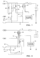
- Figure 4 illustrates a second embodiment of the present invention, which is the same as the embodiment of Figure 3 , except that it includes a different circuit element, designated 78', comprising a shunt resistor 82 having a preselected resistance value.
- the total effective load or resistance presented by the combination of the control winding 76 and the shunt resistor 82 is determined as a function of (i) the preselected resistance of resistor 82; (ii) a winding resistance of the control winding 76; and (iii) the number of turns of the primary winding and the number of turns of the control winding. This is because the resistive contribution of the winding resistance is a function of the ratio of the square of the primary turns to the square of the control winding turns.
- a one turn control winding 76 may have a resistance ranging between about 0.004-0.009 ohms (assuming the resistance of resistor 82 is zero), and for a five turn control winding, a resistance between about 0.09 and 0.22 ohms (assuming the resistance of resistor 82 is zero).
- the minimum resistance (0.22 ohms) could be produced using, for example, 31 mm of 43 AWG.
- the total, effective resistance (as defined above) may be between about 80-180 ohms.
- control winding 76 and shunt resistor 82 are configured to simulate magnetic circuit losses, just as with the first embodiment. While this embodiment has the same advantages of limiting undesirable end-of-spark ringing, it may nonetheless reduce the output of the ignition apparatus 10 insofar as it is not polarity sensitive and thus conducts in both directions, corresponding to both charging and discharging of the ignition apparatus.
- FIG. 5 is a schematic diagram of a third embodiment of the present invention, except that a separate control winding is not used, but rather a shunt resistor is directly placed across the already-existing primary winding 24.
- the circuit element 78" comprises a resistor 84 disposed across primary winding 24.
- resistor 84 may have a resistance of between about 80-180 ohms, and more particularly about 80 ohms, when the primary control winding comprises 144 turns. This embodiment obviates the need for a separate control winding 76 and is thus lower in cost than the embodiment of Figure 4 .
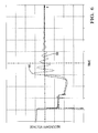
- Figure 6 is a secondary voltage versus time graph that illustrates the ringing secondary voltage as trace 86, with a ringing-suppressed output according to the invention being shown as trace 88.
- Figure 7 is a simplified schematic diagram of a fourth embodiment, which, like the embodiment of Figure 5 , does not include a separate control winding 76 but that which provides improved performance by switching in the shunt resistor only when needed.
- the embodiment of Figure 7 includes additional circuitry and is thus more expensive as the trade off for improved performance.
- the embodiment of Figure 7 includes circuit element 78"' that is responsive to an input signal, designated 94, for suppressing secondary voltage ringing.
- Circuit element 78"' includes shunt resistor 84, a silicon-controlled rectifier (SCR) 86, pull up resistor 88, an inductor 90, and a switch such as an insulated gate bipolar transistor 92 responsive to input signal 94.
- SCR silicon-controlled rectifier
- the embodiment of Figure 7 involves no change to the ignition coil (mentioned above) but does include more electronics.
- the resistor 88, inductor 90, and switch 92 form a control circuit for selectively causing the SCR 86 to conduct in response to a trigger signal 94 wherein the resistor 84 is shunted across the primary winding 24.
- Trigger signal 94 is generated, as illustrated, as a pulse by a separate circuit (not shown) when the secondary current decreases to a predetermined level (e.g. , approaches zero or in fact crosses zero) after a spark event.
- the resistor 88 is included to minimize the likelihood that a leakage spike d ⁇ / dt might turn on the SCR 86, by tying the gate and cathode terminals of the SCR 86 both to the B+ rail ( i.e., same voltage). As shown, the gate terminal of SCR 86 is connected to a common node 89.
- the transistor 92 In operation, before the signal 94 is generated, the transistor 92 is OFF.
- the SCR 86 is also OFF since the gate terminal of the SCR 86 (via resistor 88) is at the same potential as the cathode terminal of the SCR 86. Accordingly, the shunt resistor 84 is not connected across the primary winding 24, and thus presents no load.
- the transistor 92 When the signal 94 pulses, indicating that the secondary current has decreased to near zero, the transistor 92 is placed into conduction for such time as the pulse is asserted. During such time, current flows from the B+ rail through inductor 90, through transistor switch 92 to ground. This charges the inductor 90. Note, the SCR 86 is still OFF during this charging time period.
- transistor switch 92 When the signal 94 transitions back to a low/zero state, transistor switch 92 turns OFF. As a consequence, the inductor current through inductor 90 continues (albeit now not through transistor switch 92), and while ultimately dissipating, the temporary voltage rise occurring on the common node 89 (a closure signal) is nonetheless effective to turn ON the SCR 86, since the common node 89 is coupled to the gate terminal of SCR 86.
- SCR 86 turns on, it connects the shunt resistor 84 across the primary winding 24. It is the shunt resistor 84 that presents a load that dissipates the energy that would otherwise cause ringing (as described above). As above, shunt resistor 84 may have a value of between about 80-180 ohms.
- FIG 8 is a schematic diagram of a fifth embodiment of the present invention, featuring simpler electronics.
- another control winding designated control winding 96
- the control winding 96 is a tap off of the secondary winding 30, as shown.
- a circuit element 78"" includes a shunt resistor 98 and a switch 100.
- Shunt resistor 98 is shown schematically.
- Switch (NPN transistor) 100 is configured to selectively switch in the shunt resistor 98 that is configured to dissipate residual, existent electrical charge to suppress ringing, as described above, all in accordance with a trigger signal 102.
- Signal 102 may be the same as signal 94, namely, a trigger signal indicative of when the secondary current arising due to a spark event has decreased to a predetermined level (e.g. , nearing zero or crossing zero). Operation is the same as for the embodiment of Figure 4 , except that the load presented by the resistor 98 is only selectively inserted in series with the control winding.
- the invention provides a structure in the magnetic circuit that is configured to bleed off residual electrical charge to hasten decay of the ringing in the secondary voltage after the spark event.
- FIG 5 lowermost axial extent of any of the components in the magnetic circuit is illustrated by the line designated "B", which substantially corresponds to the lowermost axial edge or bottom of shield 36.
- the uppermost axial extent of any of the components in the magnetic circuit is illustrated by the line designated "C", which substantially corresponds to the uppermost axial edge or top of shield 36.
- Shield 36, core 16 and magnets 18, 20 (if present) generally extend about the same axial length, and are axially co-extensive (i.e. , the tops and bottoms are aligned).
- magnetic circuit means at least within the axial range between lines "B" and "C”.
- apparatus 10 includes core 16, optional first and second magnets 18, 20, primary winding 24, a first layer of encapsulant such as an epoxy potting material layer 26, a secondary winding spool 28, secondary winding 30, a second epoxy potting material layer 32, a case 34, shield 36, a low-voltage (LV) connector body 38, a high-voltage (HV) connector assembly 40.
- Core 16 may be elongated, having a main, longitudinal axis "A" associated therewith. Core 16 includes an upper, first end 42, and a lower, second end 44. Core 16 may be a conventional core known to those of ordinary skill in the art and comprise magnetically-permeable material. As illustrated, core 16, in the preferred embodiment, takes a generally cylindrical shape (which is a generally circular shape in radial cross-section), and may comprise compression molded insulated iron particles.
- Magnets 18 and 20 may be optionally included in ignition apparatus 10 as part of the magnetic circuit, and provide a magnetic bias for improved performance.
- the construction of magnets such as magnets 18 and 20, as well as their use and effect on performance, is well understood by those of ordinary skill in the art. It should be understood that magnets 18 and 20 are optional in ignition apparatus 10, and may be omitted, albeit with a reduced level of performance, which may be acceptable, depending on performance requirements.
- Primary winding 24 may be wound directly onto core 16 in a manner known in the art.
- Primary winding 24 includes first and second ends and is configured to carry a primary current I P for charging apparatus 10 upon control of ignition system 11.
- Winding 24 may comprise magnet wire, with a thickness of between about 20-23 AWG. Winding 24 may be implemented using known approaches and conventional materials.
- Layers 26 and 32 comprise an encapsulant suitable for providing electrical insulation within ignition apparatus 10.
- the encapsulant comprises epoxy potting material.
- the epoxy potting material introduced in layers 26, and 32 may be introduced into annular potting channels defined (i) between primary winding 24 and secondary winding spool 28, and, (ii) between secondary winding 30 and case 34.
- the potting channels are filled with potting material, in the illustrated embodiment, up to approximately the level designated "L".
- layer 26 may be between about 0.1 mm and 1.0 mm thick. Of course, a variety of other thicknesses are possible depending on flow characteristics and insulating characteristics of the encapsulant.
- the potting material also provides protection from environmental factors which may be encountered during the service life of ignition apparatus 10. There is a number of suitable epoxy potting materials well known to those of ordinary skill in the art.
- Secondary winding spool 28 is configured to receive and retain secondary winding 30.
- Spool 28 is disposed adjacent to and radially outwardly of the central components comprising core 16, primary winding 24, and epoxy potting layer 26, and, preferably, is in coaxial relationship therewith.
- Spool 28 may comprise any one of a number of conventional spool configurations known to those of ordinary skill in the art.
- spool 28 is configured to receive one continuous secondary winding (e.g. , progressive winding), as is known.
- a configuration adapted for use with a segmented winding strategy e.g. , a spool of the type having a plurality of axially spaced ribs forming a plurality of channels therebetween for accepting windings
- a segmented winding strategy e.g. , a spool of the type having a plurality of axially spaced ribs forming a plurality of channels therebetween for accepting windings
- the depth of the secondary winding in the illustrated embodiment may decrease from the top of spool 28 ( i.e., near the upper end 42 of core 16), to the other end of spool 28 ( i.e., near the lower end 44) by way of a progressive gradual flare of the spool body.
- the result of the flare or taper is to increase the radial distance (i.e. , taken with respect to axis "A") between primary winding 24 and secondary winding 30, progressively, from the top to the bottom.
- the voltage gradient in the axial direction which increases toward the spark plug end (i.e., high voltage end) of the secondary winding, may require increased dielectric insulation between the secondary and primary windings, and, may be provided for by way of the progressively increased separation between the secondary and primary windings.
- Spool 28 is formed generally of electrical insulating material having properties suitable for use in a relatively high temperature environment.
- spool 28 may comprise plastic material such as PPO/PS (e.g. , NORYL available from General Electric) or polybutylene terephthalate (PBT) thermoplastic polyester.
- PPO/PS e.g. , NORYL available from General Electric
- PBT polybutylene terephthalate
- Spool 28 may further include a first annular feature 48 and a second annular feature 50 formed at axially opposite ends thereof.
- Features 48 and 50 may be configured so as to engage an inner surface of case 34 to locate, align, and center the spool 28 in the cavity of case 34.
- spool 28 tapers on a lower end thereof to a reduced diameter, generally cylindrical outer surface sized to provide an interference fit with respect to a corresponding through-aperture at the lower end of case 34.
- the spool body includes a blind bore or well at the spark plug end configured in size and shape to accommodate the size and shape of HV connector assembly 40.
- spool 28 includes an electrically conductive (i.e. , metal) high-voltage (HV) terminal 52 disposed therein configured to connect the HV end of secondary winding 30 to the HV connector assembly 40.
- HV high-voltage
- Figure 5 also shows secondary winding 30 in cross-section.
- Secondary winding 30, as described above, is wound on spool 28, and includes a low voltage end and a high voltage end.
- the low voltage end may be connected to ground by way of a ground connection through LV connector body 38 in a manner known to those of ordinary skill in the art.
- the high voltage end is connected to HV terminal 52 in a manner described above.
- Winding 30 may be implemented using conventional approaches and material known to those of ordinary skill in the art.
- Case 34 includes an inner, generally cylindrical surface 54, an outer surface 56, a first annular shoulder 58, a flange 60, an upper through-bore 62, and a lower through bore 64.
- Inner surface 54 is configured in size to receive and retain the core 16/primary winding 24/spool 28/secondary winding 30 assembly.
- the inner surface 54 of case 34 may be slightly spaced from spool 28, particularly the annular spacing features 48, 50 thereof (as shown), or may engage the spacing features 48, 50.
- Annular shoulder 58 and flange 60 are located near the lower, and upper ends of case 34, respectively.
- Shoulder 58 is formed in size and shape to engage and support a bottommost circumferential edge of shield 36.
- flange 60 is configured in size and shape to engage and support an uppermost circumferential edge of shield 36.
- Bore 62 is configured in size and shape to receive the combined assembly of core 16/primary winding 24/spool 28/secondary winding 30.
- Bore 64 is defined by an inner surface thereof configured in size and shape (i.e., generally cylindrical) to provide an interference fit with an outer surface of spool body 28 ( i.e., a lowermost portion thereof), as described above. When the lowermost body portion of spool 28 is inserted in bore 64, therefore, a seal is made.
- Case 34 is formed of electrical insulating material, and may comprise conventional materials known to those of ordinary skill in the art (e.g. , the PBT thermoplastic polyester material referred to above).
- Shield 36 is generally annular in shape and is disposed radially outwardly of case 34, and, preferably, engages outer surface 56 of case 34.
- the shield 36 is preferably comprises magnetically-permeable material that is also electrically conductive material, and, more preferably metal, such as silicon steel or other adequate magnetic material.
- Shield 36 provides not only a protective barrier for ignition apparatus 10 generally, but, further, provides a magnetic path for the magnetic circuit portion of ignition apparatus 10.
- Shield 36 may nominally be about 0.50 mm thick, in one embodiment.
- Shield 36 may be grounded by way of an internal grounding strap, finger or the like (not shown) well know to those of ordinary skill in the art.
- Shield 36 may comprise multiple, individual sheets 36.
- Low voltage connector body 38 is configured to, among other things, electrically connect the first and second ends of primary winding 24 to an energization source, such as, the energization circuitry included in ignition system 11.
- Connector body 38 is generally formed of electrical insulating material, but also includes a plurality of electrically conductive output terminals 66 ( e.g. , pins for ground, primary winding leads, etc.). Terminals 66 are coupled electrically, internally through connector body 38, in a manner known to those of ordinary skill in the art, and are thereafter connected to various parts of apparatus 10, also in a manner generally know to those of ordinary skill in the art.
- HV connector assembly 40 may include a spring contact 68 or the like, which is electrically coupled to HV terminal 52 disposed in a blind bore portion formed in a lowermost end of spool 28.
- Contact spring 68 is configured to engage a high-voltage connector terminal of spark plug 13. This arrangement for coupling the high voltage developed by secondary winding 30 to plug 13 is exemplary only; a number of alternative connector arrangements, particularly spring-biased arrangements, are known in the art.
Landscapes
- Engineering & Computer Science (AREA)
- Power Engineering (AREA)
- Chemical & Material Sciences (AREA)
- Combustion & Propulsion (AREA)
- Mechanical Engineering (AREA)
- General Engineering & Computer Science (AREA)
- Ignition Installations For Internal Combustion Engines (AREA)
Applications Claiming Priority (1)
| Application Number | Priority Date | Filing Date | Title |
|---|---|---|---|
| US11/747,662 US7778002B2 (en) | 2007-05-11 | 2007-05-11 | Method and apparatus to reduce ring out in an ignition coil to allow for ion sense processing |
Publications (2)
| Publication Number | Publication Date |
|---|---|
| EP1990813A1 true EP1990813A1 (de) | 2008-11-12 |
| EP1990813B1 EP1990813B1 (de) | 2012-04-04 |
Family
ID=39642971
Family Applications (1)
| Application Number | Title | Priority Date | Filing Date |
|---|---|---|---|
| EP08155528A Not-in-force EP1990813B1 (de) | 2007-05-11 | 2008-04-30 | Verfahren und Gerät zur Reduzierung der Nachschwingungen in einer Zündspule zur Ionenabfühlverarbeitung |
Country Status (3)
| Country | Link |
|---|---|
| US (1) | US7778002B2 (de) |
| EP (1) | EP1990813B1 (de) |
| AT (1) | ATE552600T1 (de) |
Cited By (1)
| Publication number | Priority date | Publication date | Assignee | Title |
|---|---|---|---|---|
| EP3222845A1 (de) | 2016-03-24 | 2017-09-27 | Hoerbiger Kompressortechnik Holding GmbH | Kapazitives zündsystemmit ionisationsstrommesung und unterdrückung von wechselstrom-schwingung |
Families Citing this family (6)
| Publication number | Priority date | Publication date | Assignee | Title |
|---|---|---|---|---|
| DE102010029228A1 (de) * | 2010-01-14 | 2011-07-21 | Robert Bosch GmbH, 70469 | Verfahren und Steuereinheit zum Steuern eines elektrischen Bauelementes |
| US8502495B2 (en) * | 2011-01-24 | 2013-08-06 | Ford Global Technologies, Llc | Method and system for managing vehicle battery charge |
| DE102014110962B3 (de) * | 2014-07-31 | 2015-11-05 | Borgwarner Ludwigsburg Gmbh | Entstörwiderstand für ein Zündsystem und Zündkerzenstecker mit einem solchen Entstörwiderstand |
| US20180351333A1 (en) * | 2017-06-05 | 2018-12-06 | Fives Cinetic Corp. | Method of testing a spark plug, and a testing station therefor |
| SE542389C2 (en) * | 2018-09-04 | 2020-04-21 | Sem Ab | An ignition system and method controlling spark ignited combustion engines |
| JP6964720B1 (ja) * | 2020-06-12 | 2021-11-10 | 三菱電機株式会社 | 点火装置 |
Citations (6)
| Publication number | Priority date | Publication date | Assignee | Title |
|---|---|---|---|---|
| US3007082A (en) * | 1959-06-11 | 1961-10-31 | William R Kappele | High efficiency ignition system |
| US3403666A (en) * | 1965-06-10 | 1968-10-01 | Bosch Gmbh Robert | Ignition systems with ignition coils for internal combustion engines |
| US3910247A (en) | 1973-07-25 | 1975-10-07 | Gunter Hartig | Method and apparatus for distributorless ignition |
| US6360587B1 (en) | 2000-08-10 | 2002-03-26 | Delphi Technologies, Inc. | Pre-ignition detector |
| US6615811B1 (en) | 2002-03-04 | 2003-09-09 | Delphi Technologies, Inc. | Ignition coil integrated ion sense with combustion and knock outputs |
| US20060176134A1 (en) * | 2005-02-10 | 2006-08-10 | Denso Corporation | Ignition coil |
Family Cites Families (9)
| Publication number | Priority date | Publication date | Assignee | Title |
|---|---|---|---|---|
| GB1245245A (en) * | 1967-10-11 | 1971-09-08 | Emi Ltd | Improvements in or relating to proximity fuzes for missiles |
| US4005694A (en) * | 1975-08-18 | 1977-02-01 | The Plasmatronics Company | Electronic ignition system |
| US5051572A (en) * | 1990-04-06 | 1991-09-24 | Mcdonnell Douglas Corporation | Photomultiplier gating circuit |
| US6338267B1 (en) * | 2000-02-17 | 2002-01-15 | Delphi Technologies, Inc. | System for rejecting noise in ignition knock data |
| US6450157B1 (en) * | 2000-07-03 | 2002-09-17 | Delphi Technologies, Inc. | Automotive ignition system with adaptable start-of-dwell ring damping |
| US6437674B1 (en) * | 2001-01-31 | 2002-08-20 | Delphi Technologies, Inc. | Ignition apparatus having built-in noise suppression |
| DE10155972A1 (de) * | 2001-11-14 | 2003-05-22 | Bosch Gmbh Robert | Zündanlage und Verfahren zum Betreiben einer Zündanlage |
| US6666196B2 (en) * | 2002-01-10 | 2003-12-23 | Delphi Technologies, Inc. | Ignition system having improved spark-on-make blocking diode implementation |
| US6771521B1 (en) * | 2003-02-20 | 2004-08-03 | Delta Electronics, Inc. | Active snubber for synchronous rectifier |
-
2007
- 2007-05-11 US US11/747,662 patent/US7778002B2/en not_active Expired - Fee Related
-
2008
- 2008-04-30 EP EP08155528A patent/EP1990813B1/de not_active Not-in-force
- 2008-04-30 AT AT08155528T patent/ATE552600T1/de active
Patent Citations (6)
| Publication number | Priority date | Publication date | Assignee | Title |
|---|---|---|---|---|
| US3007082A (en) * | 1959-06-11 | 1961-10-31 | William R Kappele | High efficiency ignition system |
| US3403666A (en) * | 1965-06-10 | 1968-10-01 | Bosch Gmbh Robert | Ignition systems with ignition coils for internal combustion engines |
| US3910247A (en) | 1973-07-25 | 1975-10-07 | Gunter Hartig | Method and apparatus for distributorless ignition |
| US6360587B1 (en) | 2000-08-10 | 2002-03-26 | Delphi Technologies, Inc. | Pre-ignition detector |
| US6615811B1 (en) | 2002-03-04 | 2003-09-09 | Delphi Technologies, Inc. | Ignition coil integrated ion sense with combustion and knock outputs |
| US20060176134A1 (en) * | 2005-02-10 | 2006-08-10 | Denso Corporation | Ignition coil |
Cited By (2)
| Publication number | Priority date | Publication date | Assignee | Title |
|---|---|---|---|---|
| EP3222845A1 (de) | 2016-03-24 | 2017-09-27 | Hoerbiger Kompressortechnik Holding GmbH | Kapazitives zündsystemmit ionisationsstrommesung und unterdrückung von wechselstrom-schwingung |
| EP3222845B1 (de) * | 2016-03-24 | 2023-08-16 | Altronic, LLC | Kapazitives zündsystem mit ionisationsstrommesung und unterdrückung von wechselstrom-schwingung |
Also Published As
| Publication number | Publication date |
|---|---|
| ATE552600T1 (de) | 2012-04-15 |
| EP1990813B1 (de) | 2012-04-04 |
| US7778002B2 (en) | 2010-08-17 |
| US20080278884A1 (en) | 2008-11-13 |
Similar Documents
| Publication | Publication Date | Title |
|---|---|---|
| EP1990813B1 (de) | Verfahren und Gerät zur Reduzierung der Nachschwingungen in einer Zündspule zur Ionenabfühlverarbeitung | |
| US8387598B2 (en) | Ignition system open secondary detection | |
| EP2825767A1 (de) | Zündsystem | |
| US20160138552A1 (en) | High-frequency discharge ignition device | |
| US6679236B2 (en) | Ignition system having a high resistivity core | |
| US6437674B1 (en) | Ignition apparatus having built-in noise suppression | |
| JP6781480B2 (ja) | 一次インダクタンスを短絡させることによるスパークプラグのコイルのイオン化検出器 | |
| EP3104379B1 (de) | Funkenzündungstransformator für nichtlinearen sekundärstrom | |
| JP5802117B2 (ja) | 点火装置及び点火システム | |
| US6679235B1 (en) | High power ignition system having high impedance to protect the transformer | |
| US20060152865A1 (en) | Circuit for protecting a transistor from an open secondary ignition coil | |
| EP1318298B1 (de) | Zündapparat mit erhöhtem Ableitstrom zum Befördern des Ermitteln eines Ionisierungsstromes | |
| JP2014070504A (ja) | イオン電流検出装置 | |
| US20060176134A1 (en) | Ignition coil | |
| JP4672773B2 (ja) | 測定信号を、詳細には内燃機関の点火プラグの電極間のイオン流に対応する信号を高電圧側検知するための装置 | |
| US7710229B2 (en) | Ignition coil and ignition coil system having the same | |
| EP0663526B1 (de) | Zündsystem einer inneren Brennkraftmaschine | |
| US20070256655A1 (en) | Ignition Coil | |
| US12416282B2 (en) | Method and apparatus to control an ignition system | |
| JP2014070505A (ja) | イオン電流検出装置 | |
| JP6026298B2 (ja) | イオン電流検出装置 | |
| US7228854B1 (en) | Ignition coil apparatus for an internal combustion engine | |
| JP2006287089A (ja) | 内燃機関用点火コイル | |
| JP2014070503A (ja) | イオン電流検出装置 | |
| JPS6040865Y2 (ja) | 内燃機関用点火装置の二次電圧制限装置 |
Legal Events
| Date | Code | Title | Description |
|---|---|---|---|
| PUAI | Public reference made under article 153(3) epc to a published international application that has entered the european phase |
Free format text: ORIGINAL CODE: 0009012 |
|
| AK | Designated contracting states |
Kind code of ref document: A1 Designated state(s): AT BE BG CH CY CZ DE DK EE ES FI FR GB GR HR HU IE IS IT LI LT LU LV MC MT NL NO PL PT RO SE SI SK TR |
|
| AX | Request for extension of the european patent |
Extension state: AL BA MK RS |
|
| 17P | Request for examination filed |
Effective date: 20090512 |
|
| AKX | Designation fees paid |
Designated state(s): AT BE BG CH CY CZ DE DK EE ES FI FR GB GR HR HU IE IS IT LI LT LU LV MC MT NL NO PL PT RO SE SI SK TR |
|
| 17Q | First examination report despatched |
Effective date: 20090710 |
|
| GRAP | Despatch of communication of intention to grant a patent |
Free format text: ORIGINAL CODE: EPIDOSNIGR1 |
|
| GRAS | Grant fee paid |
Free format text: ORIGINAL CODE: EPIDOSNIGR3 |
|
| GRAA | (expected) grant |
Free format text: ORIGINAL CODE: 0009210 |
|
| AK | Designated contracting states |
Kind code of ref document: B1 Designated state(s): AT BE BG CH CY CZ DE DK EE ES FI FR GB GR HR HU IE IS IT LI LT LU LV MC MT NL NO PL PT RO SE SI SK TR |
|
| REG | Reference to a national code |
Ref country code: GB Ref legal event code: FG4D |
|
| REG | Reference to a national code |
Ref country code: CH Ref legal event code: EP |
|
| REG | Reference to a national code |
Ref country code: AT Ref legal event code: REF Ref document number: 552600 Country of ref document: AT Kind code of ref document: T Effective date: 20120415 |
|
| REG | Reference to a national code |
Ref country code: IE Ref legal event code: FG4D |
|
| REG | Reference to a national code |
Ref country code: DE Ref legal event code: R096 Ref document number: 602008014573 Country of ref document: DE Effective date: 20120531 |
|
| REG | Reference to a national code |
Ref country code: NL Ref legal event code: VDEP Effective date: 20120404 |
|
| REG | Reference to a national code |
Ref country code: AT Ref legal event code: MK05 Ref document number: 552600 Country of ref document: AT Kind code of ref document: T Effective date: 20120404 |
|
| LTIE | Lt: invalidation of european patent or patent extension |
Effective date: 20120404 |
|
| PG25 | Lapsed in a contracting state [announced via postgrant information from national office to epo] |
Ref country code: NO Free format text: LAPSE BECAUSE OF FAILURE TO SUBMIT A TRANSLATION OF THE DESCRIPTION OR TO PAY THE FEE WITHIN THE PRESCRIBED TIME-LIMIT Effective date: 20120704 Ref country code: IS Free format text: LAPSE BECAUSE OF FAILURE TO SUBMIT A TRANSLATION OF THE DESCRIPTION OR TO PAY THE FEE WITHIN THE PRESCRIBED TIME-LIMIT Effective date: 20120804 Ref country code: SI Free format text: LAPSE BECAUSE OF FAILURE TO SUBMIT A TRANSLATION OF THE DESCRIPTION OR TO PAY THE FEE WITHIN THE PRESCRIBED TIME-LIMIT Effective date: 20120404 Ref country code: CY Free format text: LAPSE BECAUSE OF FAILURE TO SUBMIT A TRANSLATION OF THE DESCRIPTION OR TO PAY THE FEE WITHIN THE PRESCRIBED TIME-LIMIT Effective date: 20120404 Ref country code: SE Free format text: LAPSE BECAUSE OF FAILURE TO SUBMIT A TRANSLATION OF THE DESCRIPTION OR TO PAY THE FEE WITHIN THE PRESCRIBED TIME-LIMIT Effective date: 20120404 Ref country code: LT Free format text: LAPSE BECAUSE OF FAILURE TO SUBMIT A TRANSLATION OF THE DESCRIPTION OR TO PAY THE FEE WITHIN THE PRESCRIBED TIME-LIMIT Effective date: 20120404 Ref country code: PL Free format text: LAPSE BECAUSE OF FAILURE TO SUBMIT A TRANSLATION OF THE DESCRIPTION OR TO PAY THE FEE WITHIN THE PRESCRIBED TIME-LIMIT Effective date: 20120404 Ref country code: FI Free format text: LAPSE BECAUSE OF FAILURE TO SUBMIT A TRANSLATION OF THE DESCRIPTION OR TO PAY THE FEE WITHIN THE PRESCRIBED TIME-LIMIT Effective date: 20120404 |
|
| PG25 | Lapsed in a contracting state [announced via postgrant information from national office to epo] |
Ref country code: GR Free format text: LAPSE BECAUSE OF FAILURE TO SUBMIT A TRANSLATION OF THE DESCRIPTION OR TO PAY THE FEE WITHIN THE PRESCRIBED TIME-LIMIT Effective date: 20120705 Ref country code: PT Free format text: LAPSE BECAUSE OF FAILURE TO SUBMIT A TRANSLATION OF THE DESCRIPTION OR TO PAY THE FEE WITHIN THE PRESCRIBED TIME-LIMIT Effective date: 20120806 Ref country code: HR Free format text: LAPSE BECAUSE OF FAILURE TO SUBMIT A TRANSLATION OF THE DESCRIPTION OR TO PAY THE FEE WITHIN THE PRESCRIBED TIME-LIMIT Effective date: 20120404 Ref country code: LV Free format text: LAPSE BECAUSE OF FAILURE TO SUBMIT A TRANSLATION OF THE DESCRIPTION OR TO PAY THE FEE WITHIN THE PRESCRIBED TIME-LIMIT Effective date: 20120404 Ref country code: MC Free format text: LAPSE BECAUSE OF NON-PAYMENT OF DUE FEES Effective date: 20120430 |
|
| REG | Reference to a national code |
Ref country code: CH Ref legal event code: PL |
|
| PG25 | Lapsed in a contracting state [announced via postgrant information from national office to epo] |
Ref country code: BE Free format text: LAPSE BECAUSE OF FAILURE TO SUBMIT A TRANSLATION OF THE DESCRIPTION OR TO PAY THE FEE WITHIN THE PRESCRIBED TIME-LIMIT Effective date: 20120404 |
|
| PG25 | Lapsed in a contracting state [announced via postgrant information from national office to epo] |
Ref country code: CH Free format text: LAPSE BECAUSE OF NON-PAYMENT OF DUE FEES Effective date: 20120430 Ref country code: LI Free format text: LAPSE BECAUSE OF NON-PAYMENT OF DUE FEES Effective date: 20120430 Ref country code: SK Free format text: LAPSE BECAUSE OF FAILURE TO SUBMIT A TRANSLATION OF THE DESCRIPTION OR TO PAY THE FEE WITHIN THE PRESCRIBED TIME-LIMIT Effective date: 20120404 Ref country code: AT Free format text: LAPSE BECAUSE OF FAILURE TO SUBMIT A TRANSLATION OF THE DESCRIPTION OR TO PAY THE FEE WITHIN THE PRESCRIBED TIME-LIMIT Effective date: 20120404 Ref country code: DK Free format text: LAPSE BECAUSE OF FAILURE TO SUBMIT A TRANSLATION OF THE DESCRIPTION OR TO PAY THE FEE WITHIN THE PRESCRIBED TIME-LIMIT Effective date: 20120404 Ref country code: CZ Free format text: LAPSE BECAUSE OF FAILURE TO SUBMIT A TRANSLATION OF THE DESCRIPTION OR TO PAY THE FEE WITHIN THE PRESCRIBED TIME-LIMIT Effective date: 20120404 Ref country code: EE Free format text: LAPSE BECAUSE OF FAILURE TO SUBMIT A TRANSLATION OF THE DESCRIPTION OR TO PAY THE FEE WITHIN THE PRESCRIBED TIME-LIMIT Effective date: 20120404 Ref country code: NL Free format text: LAPSE BECAUSE OF FAILURE TO SUBMIT A TRANSLATION OF THE DESCRIPTION OR TO PAY THE FEE WITHIN THE PRESCRIBED TIME-LIMIT Effective date: 20120404 Ref country code: RO Free format text: LAPSE BECAUSE OF FAILURE TO SUBMIT A TRANSLATION OF THE DESCRIPTION OR TO PAY THE FEE WITHIN THE PRESCRIBED TIME-LIMIT Effective date: 20120404 |
|
| PLBE | No opposition filed within time limit |
Free format text: ORIGINAL CODE: 0009261 |
|
| STAA | Information on the status of an ep patent application or granted ep patent |
Free format text: STATUS: NO OPPOSITION FILED WITHIN TIME LIMIT |
|
| PG25 | Lapsed in a contracting state [announced via postgrant information from national office to epo] |
Ref country code: IT Free format text: LAPSE BECAUSE OF FAILURE TO SUBMIT A TRANSLATION OF THE DESCRIPTION OR TO PAY THE FEE WITHIN THE PRESCRIBED TIME-LIMIT Effective date: 20120404 |
|
| 26N | No opposition filed |
Effective date: 20130107 |
|
| PG25 | Lapsed in a contracting state [announced via postgrant information from national office to epo] |
Ref country code: IE Free format text: LAPSE BECAUSE OF NON-PAYMENT OF DUE FEES Effective date: 20120430 Ref country code: ES Free format text: LAPSE BECAUSE OF FAILURE TO SUBMIT A TRANSLATION OF THE DESCRIPTION OR TO PAY THE FEE WITHIN THE PRESCRIBED TIME-LIMIT Effective date: 20120715 |
|
| REG | Reference to a national code |
Ref country code: DE Ref legal event code: R097 Ref document number: 602008014573 Country of ref document: DE Effective date: 20130107 |
|
| PG25 | Lapsed in a contracting state [announced via postgrant information from national office to epo] |
Ref country code: MT Free format text: LAPSE BECAUSE OF FAILURE TO SUBMIT A TRANSLATION OF THE DESCRIPTION OR TO PAY THE FEE WITHIN THE PRESCRIBED TIME-LIMIT Effective date: 20120404 Ref country code: BG Free format text: LAPSE BECAUSE OF FAILURE TO SUBMIT A TRANSLATION OF THE DESCRIPTION OR TO PAY THE FEE WITHIN THE PRESCRIBED TIME-LIMIT Effective date: 20120704 |
|
| PGFP | Annual fee paid to national office [announced via postgrant information from national office to epo] |
Ref country code: GB Payment date: 20130429 Year of fee payment: 6 Ref country code: DE Payment date: 20130429 Year of fee payment: 6 |
|
| PGFP | Annual fee paid to national office [announced via postgrant information from national office to epo] |
Ref country code: FR Payment date: 20130506 Year of fee payment: 6 |
|
| PG25 | Lapsed in a contracting state [announced via postgrant information from national office to epo] |
Ref country code: TR Free format text: LAPSE BECAUSE OF FAILURE TO SUBMIT A TRANSLATION OF THE DESCRIPTION OR TO PAY THE FEE WITHIN THE PRESCRIBED TIME-LIMIT Effective date: 20120404 |
|
| PG25 | Lapsed in a contracting state [announced via postgrant information from national office to epo] |
Ref country code: LU Free format text: LAPSE BECAUSE OF NON-PAYMENT OF DUE FEES Effective date: 20120430 |
|
| PG25 | Lapsed in a contracting state [announced via postgrant information from national office to epo] |
Ref country code: HU Free format text: LAPSE BECAUSE OF FAILURE TO SUBMIT A TRANSLATION OF THE DESCRIPTION OR TO PAY THE FEE WITHIN THE PRESCRIBED TIME-LIMIT Effective date: 20080430 |
|
| REG | Reference to a national code |
Ref country code: DE Ref legal event code: R119 Ref document number: 602008014573 Country of ref document: DE |
|
| GBPC | Gb: european patent ceased through non-payment of renewal fee |
Effective date: 20140430 |
|
| REG | Reference to a national code |
Ref country code: FR Ref legal event code: ST Effective date: 20141231 |
|
| REG | Reference to a national code |
Ref country code: DE Ref legal event code: R119 Ref document number: 602008014573 Country of ref document: DE Effective date: 20141101 |
|
| PG25 | Lapsed in a contracting state [announced via postgrant information from national office to epo] |
Ref country code: GB Free format text: LAPSE BECAUSE OF NON-PAYMENT OF DUE FEES Effective date: 20140430 Ref country code: DE Free format text: LAPSE BECAUSE OF NON-PAYMENT OF DUE FEES Effective date: 20141101 |
|
| PG25 | Lapsed in a contracting state [announced via postgrant information from national office to epo] |
Ref country code: FR Free format text: LAPSE BECAUSE OF NON-PAYMENT OF DUE FEES Effective date: 20140430 |