EP1990889A2 - Dispositif de protection pour cellule assemblée, et unité de bloc-batterie - Google Patents
Dispositif de protection pour cellule assemblée, et unité de bloc-batterie Download PDFInfo
- Publication number
- EP1990889A2 EP1990889A2 EP08005120A EP08005120A EP1990889A2 EP 1990889 A2 EP1990889 A2 EP 1990889A2 EP 08005120 A EP08005120 A EP 08005120A EP 08005120 A EP08005120 A EP 08005120A EP 1990889 A2 EP1990889 A2 EP 1990889A2
- Authority
- EP
- European Patent Office
- Prior art keywords
- unit
- discharging
- protection
- consumption
- current
- Prior art date
- Legal status (The legal status is an assumption and is not a legal conclusion. Google has not performed a legal analysis and makes no representation as to the accuracy of the status listed.)
- Granted
Links
Images



Classifications
-
- H—ELECTRICITY
- H02—GENERATION; CONVERSION OR DISTRIBUTION OF ELECTRIC POWER
- H02J—ELECTRIC POWER NETWORKS; CIRCUIT ARRANGEMENTS OR SYSTEMS FOR SUPPLYING OR DISTRIBUTING ELECTRIC POWER; SYSTEMS FOR STORING ELECTRIC ENERGY
- H02J7/00—Circuit arrangements for charging or discharging batteries or for supplying loads from batteries
- H02J7/50—Circuit arrangements for charging or discharging batteries or for supplying loads from batteries acting upon multiple batteries simultaneously or sequentially
- H02J7/52—Circuit arrangements for charging or discharging batteries or for supplying loads from batteries acting upon multiple batteries simultaneously or sequentially for charge balancing, e.g. equalisation of charge between batteries
- H02J7/54—Passive balancing, e.g. using resistors or parallel MOSFETs
-
- Y—GENERAL TAGGING OF NEW TECHNOLOGICAL DEVELOPMENTS; GENERAL TAGGING OF CROSS-SECTIONAL TECHNOLOGIES SPANNING OVER SEVERAL SECTIONS OF THE IPC; TECHNICAL SUBJECTS COVERED BY FORMER USPC CROSS-REFERENCE ART COLLECTIONS [XRACs] AND DIGESTS
- Y02—TECHNOLOGIES OR APPLICATIONS FOR MITIGATION OR ADAPTATION AGAINST CLIMATE CHANGE
- Y02T—CLIMATE CHANGE MITIGATION TECHNOLOGIES RELATED TO TRANSPORTATION
- Y02T10/00—Road transport of goods or passengers
- Y02T10/60—Other road transportation technologies with climate change mitigation effect
- Y02T10/70—Energy storage systems for electromobility, e.g. batteries
Definitions
- the present invention relates to a protection device for protecting an assembled cell including a plurality of secondary batteries connected in series, and a battery pack unit incorporating a protection device.
- a high energy density secondary battery has been widely used as a power supply for small information equipment such as a portable phone and a notebook personal computer.
- the secondary batteries are often connected in series, the number of which corresponds to a voltage and current necessary for an objective apparatus or often used as an assembled cell in which they are connected in series or in parallel. Because a power supply voltage of the aforementioned small information equipment is about several V to 10 V, the number of series connections in the assembled cell is 1 to 3.
- a prominent problem in connecting the batteries in series is a fluctuation between individual batteries (called cells).
- the fluctuation includes, for example, fluctuation in capacity, fluctuation in impedance, and fluctuation in the state of charge (SOC).
- SOC state of charge
- a fluctuation which likely leads to an error of these ones is a fluctuation in voltage which is one of the fluctuations in the SOC.
- a cell having a higher voltage or a cell having a lower voltage than the average is generated in a fully charged state of the assembled cell.
- the cell having a higher voltage is turned into an overcharged state, whereby deterioration is intensified. If the charge is repeated, the cell whose deterioration is intensified by the overcharge has a reduced capacity, so that the overcharge is progressed, thereby accelerating the deterioration. As a result, the cycle service life of the assembled battery is shortened extremely than the service life of the cell.
- the cause for the fluctuation in the SOC includes not only the fluctuation of the cell in an initial period but also a factor generated during use of the assembled battery. For example, sometime there is a difference in temperature among the cells or currents discharged from each cell are different, thereby leading to a cause for the fluctuation in the SOC. Particularly, because the protection device is complicated in the assembled cell which has many series connections to output a high voltage, the discharge current by the protection device is apt to fluctuate.
- the protection device is generally constituted of protection units provided for each battery module each having several cells to ten and several cells for the reason of restriction about withstand voltage of an integrated circuit (IC) for use in the protection device.
- Each protection unit is operated using a battery module as a power supply, measures the voltages of each cells and temperature in a corresponding battery module and communicates with protection units on the upper level and lower level in order to monitor the entire system.
- JP-A 2004-282960 has disclosed a technique for correcting a fluctuation in voltage due to a difference in consumption current among blocks if an assembled cell is divided to a plurality of blocks along a voltage detecting line by an incoming current of the voltage detecting line. More specifically, a circuit or element calculated preliminarily so that consumption currents of other blocks are matched with a consumption current of the block having a maximum current value in the blocks of the assembled cell is inserted in between a cathode and an anode of the other blocks so as to correct the fluctuation in the voltage.
- An object of the present invention is to provide a protection device for an assembled cell, which enables the service life of the assembled cell to be extended while suppressing a fluctuation in the state of charge among cells due to the difference in consumption current among the protection units, and a battery pack unit.
- protection device for an assembled cell including a plurality of battery modules connected in series, each of which includes a plurality of secondary batteries connected in series
- the protection device comprises: a plurality of protection units provided corresponding to the battery modules, each of which is configured to operate as a power supply for a corresponding battery module; and a management unit connected to the protection units in common, wherein each protection unit includes: a measuring unit configured to measure its own consumption current to obtain measurement data; a communication unit which transmits the measurement data to the management unit and receives setting data from the management unit; a discharging unit which discharges the corresponding battery module; and a control unit configured to control the discharging unit based on the measurement data and the setting data so that a total of the consumption current and a discharging current by the discharging unit is of a constant value among the protection units.
- One end of the assembled cell 1 is connected to an external connecting terminal 7 and the other end thereof is connected to an external terminal 8 through a management unit 6.
- each of the secondary batteries 3-nm is called cell.
- the protection device 4 includes protection units 5A to 5D connected respectively to the battery modules 2A to 2D and the management unit 6 common to the battery modules 2A to 2D. Although the protection device 4 may be accommodated in a different casing from the assembled cell 1, it may be in some cases accommodated in a casing 9 together with the assembled cell 1 and used as a battery pack unit 10 together with the assembled cell 1.
- the protection units 5A to 5D have a function of executing a charge prohibiting operation when a voltage (hereinafter referred to as cell voltage) of each cell of the battery modules 2A to 2D reaches a charge prohibiting voltage and of executing a discharge prohibiting operation when the cell voltage reaches a discharge prohibiting voltage when discharged. Description of the basic function is omitted here.
- the protection unit 5i is configured to mainly a microcontroller 20. A power is supplied to the microcontroller 20 and a level shifter 26 from the corresponding battery module 2i through a current detection resistor R1 which is an external element. Further, a discharging switch SW and a discharging resistor R2 are connected to the corresponding battery module 2i.
- the microcontroller 20 includes an analog-to-digital converter (ADC) 21, a voltage measuring unit 22, a consumption current measuring unit 23, an arithmetic operation unit 24, a communication unit 25 and a discharging control unit 27.
- the ADC 11 converts each cell voltage of the battery module 2i into a digital value, and the voltage are measured by the voltage measuring unit 22 based on the digital value. Further, the ADC 11 converts a voltage drop of a current detecting resistor R1 into a digital value. Based on the digital value, a consumption current (substantially, consumption current of the microcontroller 20) of the protection unit 5i is measured by the consumption current measuring unit 23.
- Voltage measurement data obtained from the voltage measuring unit 22 is given to the communication unit 25 through the arithmetic operation unit 24 or directly.
- Current measurement data obtained by the consumption current measuring unit 23 is given to the arithmetic operation unit 24 and the communication unit 25.
- the arithmetic operation unit 24 obtains a discharging current or discharging electric quantity of the corresponding battery module 2i necessary for correction of the SOC fluctuation from the current measurement data obtained by the consumption current measuring unit 23 and the setting data concerning current or electric quantity sent from the management unit 6 through the communication unit 25.
- the communication unit 25 is connected to other protection units on the upper level and lower level through the level shifter 26 so as to exchange data with the other protection units.
- the units nearer the management unit 6 are regarded to be of lower level.
- the protection unit 5A on the highest level is connected to only the protection unit 5B just on a lower level
- the protection unit 5D on the lowest level is connected to the protection units 5C just on a higher level and the management unit 6.
- the communication unit 25 transmits the current measurement data form the consumption current measuring unit 23 to the management unit 6 through a lower level protection unit and receives the setting data sent from the management unit 6, more specifically, the setting data concerning the consumption current or discharging current of the protection units 5A to 5D or discharging electric quantity through a lower protection unit.
- Reference potentials of the circuit in protection units 5A to 5D are different because the protection units 5A to 5D use the battery modules 2A to 2D connected in series of the assembled cell 1, respectively, as a power supply. That is, a higher level protection unit has a higher reference potential.
- the level shifter 26 takes a role of arranging reference potentials for a communication signal in order to enable the protection units 5A to 5D to communicate with each other or with the management unit 6 regardless of the difference in reference potential.
- the discharging control unit 27 controls the discharging switch SW based on an instruction from the arithmetic operation unit 24 to discharge the battery module 2i.
- the discharging switch SW for example, a field effect transistor (FET) or bipolar transistor is used.
- the discharging control unit 27 controls on-time or on-interval of the FET or bipolar transistor under control of, for example, pulse width modulation (PWM), or controls on-resistance of the transistor so as to discharge the discharging switch SW with a controlled discharging current.
- PWM pulse width modulation
- the discharging switch SW is controlled by the discharging control unit 27 so as to discharge a corresponding battery module by changing the magnitude of the discharging current or the discharging time in accordance with, for example, a consumption current setting value given from the management unit 6 as setting data and a value of a consumption current measured by the consumption current measuring unit 23.
- the management unit 6 is realized using a microcontroller and configured to include a communication unit 31, a total management unit 32, an arithmetic operation unit 33 and a memory unit 34 as shown in FIG. 3 .
- the communication unit 31 is provided to exchange data among the protection units 5A to 5D.
- the total management unit 32 controls entirely the protection units 5A to 5D through the communication unit 31. More specifically, the total management unit 32 controls charging and discharging of the entire assembled cell 1 in accordance with a cell voltage, etc. based on the voltage measurement data received through the communication unit 31.
- the arithmetic operation unit 33 computes to obtain setting data concerning the current or electric quantity for mainly the protection units 5A to 5D. That is, the arithmetic operation unit 33 obtains the setting data about the discharging current or discharging electric quantity for the protection units 5A to 5D in accordance with a consumption current obtained by the consumption current measuring unit 23. The setting data obtained in this way is supplied to the protection units 5A to 5D through the communication unit 31.
- the memory unit 34 is provided to store data necessary for arithmetic operation of the arithmetic operation unit 33.
- the protection device 4 is constituted of the protection units 5A to 5D provided each at the battery modules 2A to 2D each including several cells to ten and several cells as shown in FIG. 1 from the reason of restriction of the withstand voltage of the IC for use in the protection device 4.
- the respective protection units 5A to 5D measure the cell voltage and temperature of the corresponding battery modules 2A to 2D so as to control discharging of a corresponding battery module following a result of the measurement and results of measurement of other protection units. Further, the protection units 5A to 5D are operated using the corresponding battery modules 2A to 2D as power supplies, respectively, and communicate with protection units on the upper level or lower level in order to monitor the entire system.
- the protection units 5A to 5D of this embodiment are equipped with a consumption current measuring unit 23 for measuring its own consumption current and a discharge unit (switch SW and discharging control unit 27) capable of discharging each of the battery modules 2A to 2D. Consequently, the consumption currents of the protection units 5A to 5D can be arranged to a constant level so as to suppress the fluctuation in the SOC among the battery modules 2A to 2D.
- the management unit 6 is operated by an external power supply different from the assembled cell 1.
- the protection units 5A to 5D are down.
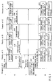
- a startup instruction is dispatched to all the protection units 5A to 5D from the management unit 6 (step S100).
- the protection units 5A to 5D are started by receiving a startup instruction, and the cell voltages of the battery modules 2A to 2D and the consumption currents I1 to I4 of the assembled cell 1 are measured by the voltage measuring unit 22 and the consumption current measuring unit 23 (steps S101 to S104).
- the management unit 6 transmits a data transmission request to the protection units 5A to 5D after a predetermined time elapses since the measurement is started (step S105).
- the data transmission request is transmitted every specified time, for example, every 100 msec.
- the protection units 5A to 5D upon receiving the data transmission request, transmit measurement data after the communication state among the protection units 5A to 5D and the management unit 6 is stabilized after a startup, for example, after about five seconds elapse, as follows.
- the protection unit 5Don the highest level transmits measurement data of the cell voltage of the battery module 2D and its own consumption current to the protection unit 5C just on a lower level through the communication unit 25 and the level shifter 26 as transmission data D4 (step S106).
- the protection unit 5C combines measurement data D3 about the cell voltage of the battery module 2C and its own consumption current with the transmission data D4 from the protection unit 5A, and transmits the transmission data (D4+D3) to the protection unit 5B just on a lower level through the communication unit 25 and the level shifter 26 (step S107).
- the protection unit 5B combines measurement data D2 about the cell voltage of the battery module 2B and its own consumption current with the transmission data D4+D3 from the protection unit 5C, and transmits the transmission data (D4+D3+D2) to the protection unit 5A just on a lowest level through the communication unit 25 and the level shifter 26 (step 5108).
- the protection unit 5A combines measurement data D1 about the cell voltage of the battery module 2A and its own consumption current with the transmission data D4+D3+D2 from the protection unit 5B, and transmits the transmission data (D4+D3+D2+D1) to the management unit 6 through the communication unit 25 and the level shifter 26 (step S109).
- the management unit 6 manages the state of charge of the entire assembled battery 1 using the measurement data of the cell voltages of the battery modules 2A to 2D in the transmission data D1+D2+D3+D4 from the protection unit 5A through the total management unit 32 and the communication unit 31 (step S110).
- the detailed description of the processing of step S110 is omitted because it is not within the spirit of the present invention.
- the management unit 6 compares the consumption currents I1 to I4 of the protection units 5A to 5D by means of the arithmetic operation unit 33 from the consumption current measurement data in the transmission data D1+D2+D3+D4 fetched in through the communication unit 31 and stores a maximum value in the memory unit 34 (step S111). Thereafter, the stored maximum value is transmitted to the protection units 5A to 5D through the communication unit 31 as a consumption current setting value 10 (step S112).
- the protection units 5A to 5D store the consumption current setting value 10 fetched in through the level shifter 26 and the communication unit 25 in the arithmetic operation unit 24 and compare the consumption currents I1 to I4 measured by the consumption current measuring unit 23 every specified time, for example, every 100 msec (steps S113 to 5116).
- the arithmetic operation unit 24 controls the discharging control unit 27 so as to discharge currents corresponding to I0-I1, 10-12, I0-I3 and 10-14 from the battery modules 2A to 2D based on this comparison result (steps S117 to S120). Consequently, all the consumption currents of the protection units 5A to 5D turn to 10 concurrently.
- the maximum value of the consumption currents I1 to I4 of the protection units 5A to 5D is obtained by the management unit 6. With this value set as the consumption current setting value 10, the protection units 5A to 5D control discharging. Thus, the consumption currents of the protection units 5A to 5D turn to 10 concurrently, so that the SOC fluctuation among the battery modules 2A to 2D due to a difference in consumption current can be suppressed.
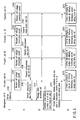
- step S111 compares the consumption currents I1 to I4 of the protection units 5A to 5D by means of the arithmetic operation unit 33 and stores a maximum value in the memory unit 34. Then, the management unit 6 transmits a difference between the stored maximum value and the respective consumption currents 11 to 14 to the protection units 5A to 5D through the communication unit 31 as discharging current setting values Is1 to Is4 (step S212).
- the protection units 5A to 5D store the discharging current setting values Is1 to Is4 fetched in through the level shifter 26 and the communication unit 25 by means of the arithmetic operation unit 24 and controls the discharging control unit 27 so as to discharge currents corresponding to Is1 to Is4 from the battery modules 2A to 2D (steps S213 to S216). Consequently, all the consumption currents of the protection units 5A to 5D become equal to the initial maximum values of the consumption currents 11 to 14 concurrently.
- the management unit 6 obtains differences between the consumption currents I1 to 14 of the protection units 5A to 5D and the maximum value as the discharging current setting values Is1 to Is4 and controls discharging of the protection units 5A to 5D by use of the obtained setting values.
- the consumption currents of the protection units 5A to 5D become equal to the maximum value concurrently as in the first processing procedure, which makes it possible to suppress the SOC fluctuation among the battery modules 2A to 2D due to a difference in consumption current.
- a third processing procedure will be described using FIG. 6 .
- a consumption electric quantity obtained by integrating consumption currents is used instead of the consumption current.
- the management unit 6 When the management unit 6 is started by an external power supply, the management unit 6 outputs a startup instruction to all the protection units 5A to 5D (step S300).
- the protection units 5A to 5D are started upon receiving the startup instruction so as to measure the cell voltages of the battery modules 2A to 2D and consumption electric quantities Q1 to Q4 by means of the voltage measuring unit 22, the consumption current measuring unit 23 and the arithmetic operation unit 24 (steps S301 to S304).
- the consumption electric quantities Q1 to Q4 are obtained by integrating consumption currents measured by the consumption current measuring unit 23 by means of the arithmetic operation unit 24, every specified time, for example, every 100 msec.
- the management unit 6 transmits a data transmission request to the protection units 5A to 5D after a specified time elapses since the measurement is started (step S305).
- the data transmission request is transmitted every specified time, for example, every 100 msec.
- the protection units 5A to 5D upon receiving the data transmission request, transmit the measurement data after the communication state between the protection units 5A to 5D and the management unit 6 is stabilized about five seconds after the startup, as follows.
- the protection unit 5D on the highest level transmits measurement data about the cell voltages of the battery module 2Dand its own consumption electric quantity to the protection unit 5C just on a lower level through the communication unit 25 and the level shifter 26 as transmission data G4 (step S306).
- the protection unit 5C combines measurement data G3 about the cell voltage of the battery module 2C and its own consumption electric quantity with the transmission data G4, and transmits the transmission data (G4+G3) to the protection unit 5B just on a lower level through the communication unit 25 and the level shifter 26 (step 5307).
- the protection unit 5B combines measurement data G2 about the cell voltage of the battery module 2B and its own consumption electric quantity with the transmission data G4+G3 from the protection unit 5C, and transmits the transmission data (G4+G3+G2) to the protection unit 5A on the lowest level through the communication unit 25 and the level shifter 26 (step S308).
- the protection unit 5A combines measurement data G1 about the cell voltage of the battery module 2A and its own consumption electric quantity with the transmission data G4+G3+G2 from the protection unit 5B, and transmits the transmission data (G4+G3+G2+G1) to the management unit 6 through the communication unit 25 and the level shifter 26 (step 5309).
- the management unit 6 manages the state of charge of the entire assembled battery 1 from the total management unit 32 through the communication unit 31 using the measurement data about the cell voltage of the battery modules 2A to 2D in the transmission data G1+G2+G3+G4 from the protection unit 5D (step S310).
- the management unit 6 compares the consumption electric quantities Q1 to Q4 of the protection units 5A to 5D by means of the arithmetic operation unit 33 from the consumption electric quantity measurement data in the transmission data G1+G2+G3+G4 fetched in through the communication unit 31 and stores a maximum value in the memory unit 34 every specified time, for example, every 100 msec (step S311). A difference between the stored maximum value and the respective consumption electric quantities Q1 to Q4 is transmitted to the protection units 5A to 5D through the communication unit 31 (step S312).
- the protection units 5A to 5D store the discharging electric quantity setting values Qs1 to Qs4 fetched in through the level shifter 26 and the communication unit 25 by means of the arithmetic operation unit 24, and controls the discharging control unit 27 so as to discharge electric quantities corresponding to Qs1 to Qs4 from the battery modules 2A to 2D every specified time, for example, 100 msec (steps S313 to S316). Consequently, all the consumption electric quantities of the protection units 5A to 5D become equal to the initial maximum values of the consumption electric quantities Q1 to Q4.
- the management unit 6 obtains differences between the consumption electric quantities Q1 to Q4 of the protection units 5A to 5D and the maximum value as the discharging electric quantity setting values Qs1 to Qs4 and controls discharging of the protection units 5A to 5D.
- the consumption electric quantities of the protection units 5A to 5D become equal to the maximum value concurrently, which makes it possible to suppress the SOC fluctuation among the battery modules 2A to 2D due to a difference in consumption electric quantity.
- Nonaqueous electrolyte secondary batteries having a discharging capacity of 3 Ah are connected in series to prepare a battery module.
- Battery modules 2A to 2D thus prepared are connected in series as shown in FIG. 1 to manufacture an assembled battery 1.
- the protection device 4 described in FIGS. 1 to 3 is connected to the assembled battery 1 and discharging of the battery modules 2A to 2D is controlled with a maximum value of the consumption currents of the protection units 5A to 5D set as a consumption current setting value in accordance with the first processing procedure described in FIG. 4 , thereby to correct the SOC fluctuation.
- the protection unit 4 described in FIGS. 1 to 3 is connected to the same assembled battery 1 as described in Specific example 1, and discharging of the battery modules 2A to 2D is controlled with a difference between the consumption currents of the protection units 5A to 5D and the maximum value set as a discharging current setting value in accordance with the second processing procedure described in FIG. 5 , thereby to correct the SOC fluctuation.
- the protection unit 4 described in FIGS. 1 to 3 is connected to the same assembled battery 1 as described in Specific example 1, and discharging of the battery modules 5A to 5D is controlled with a difference between the consumption electric quantities of the protection units 5A to 5D and the maximum value set as a discharging electric quantity setting value in accordance with the second processing procedure described in FIG. 6 , thereby to correct the SOC fluctuation.
- a protection device including neither measuring function nor discharging function for consumption current or consumption electric quantity is connected to the same assembled cell as described in Specific example 1. Then, a cycle test is carried out according to a charging/discharging method of charging the assembled cell under a constant voltage and current of 84V and 10A for an hour under 45°C and then discharging with constant voltage and constant current of 10A until the minimum value of the cell voltage reaches 3.0 V. With the charge prohibiting voltage of the protection device set to 4.35 V and the discharge prohibiting voltage set to 2.5 V, the test is terminated if the cell voltage exceeds the range.
- Table 1 shows a capacity retention after 2000 cycles and fluctuation in the cell voltage when charging is terminated (maximum value - minimum value) in Specific examples 1 to 3 and Comparative example described above.
- Table 1 Capacity retention after 2000 cycles Fluctuation in cell voltage after 2000 cycles Specific example 1 89% 40 mV Specific example 2 91% 35 mV Specific example 3 92% 37 mV Comparative example Stopped at 1250 cycles 290 mV After 1250 cycles
- Specific examples 1 to 3 show that the fluctuation in the voltage among the cells is suppressed to a small level until the test of 2000 cycles is ended, indicating a high capacity maintenance ratio.
- the fluctuation in the voltage among the cells is expanded, and a cell which exceeds the charge prohibiting voltage at 1250 cycles has appeared. Thus, the test is stopped halfway.
Landscapes
- Engineering & Computer Science (AREA)
- Power Engineering (AREA)
- Secondary Cells (AREA)
- Charge And Discharge Circuits For Batteries Or The Like (AREA)
Applications Claiming Priority (1)
| Application Number | Priority Date | Filing Date | Title |
|---|---|---|---|
| JP2007086021A JP4237804B2 (ja) | 2007-03-28 | 2007-03-28 | 組電池の保護装置及び電池パック装置 |
Publications (3)
| Publication Number | Publication Date |
|---|---|
| EP1990889A2 true EP1990889A2 (fr) | 2008-11-12 |
| EP1990889A3 EP1990889A3 (fr) | 2013-05-15 |
| EP1990889B1 EP1990889B1 (fr) | 2017-11-22 |
Family
ID=39776333
Family Applications (1)
| Application Number | Title | Priority Date | Filing Date |
|---|---|---|---|
| EP08005120.4A Ceased EP1990889B1 (fr) | 2007-03-28 | 2008-03-19 | Dispositif de protection pour cellule assemblée, et unité de bloc-batterie |
Country Status (4)
| Country | Link |
|---|---|
| US (1) | US8212523B2 (fr) |
| EP (1) | EP1990889B1 (fr) |
| JP (1) | JP4237804B2 (fr) |
| CN (1) | CN101277021B (fr) |
Cited By (2)
| Publication number | Priority date | Publication date | Assignee | Title |
|---|---|---|---|---|
| CN103997070A (zh) * | 2013-02-15 | 2014-08-20 | 欧姆龙汽车电子株式会社 | 组电池的电压监视装置 |
| EP2681797B1 (fr) | 2011-03-02 | 2018-11-14 | Commissariat à l'Énergie Atomique et aux Énergies Alternatives | Batterie avec gestion individuelle des cellules |
Families Citing this family (25)
| Publication number | Priority date | Publication date | Assignee | Title |
|---|---|---|---|---|
| CN101953017A (zh) * | 2008-02-15 | 2011-01-19 | 美商源捷有限公司 | 一种智能型容错电池管理系统 |
| JP4216898B1 (ja) * | 2008-03-28 | 2009-01-28 | 和征 榊原 | 電池パック |
| JP5565603B2 (ja) | 2009-01-23 | 2014-08-06 | ソニー株式会社 | 電力供給システムおよび電子機器 |
| JP5513138B2 (ja) * | 2009-01-28 | 2014-06-04 | 矢崎総業株式会社 | 基板 |
| JP5631549B2 (ja) * | 2009-02-13 | 2014-11-26 | セイコーインスツル株式会社 | バッテリーの保護回路装置 |
| JP5423955B2 (ja) * | 2009-06-02 | 2014-02-19 | 三菱自動車工業株式会社 | 電気自動車の電池モジュール |
| JP5461221B2 (ja) | 2010-02-12 | 2014-04-02 | 株式会社マキタ | 複数のバッテリパックを電源とする電動工具 |
| JP5432761B2 (ja) * | 2010-02-12 | 2014-03-05 | 株式会社マキタ | 複数のバッテリパックを電源とする電動工具 |
| JP4602471B1 (ja) | 2010-04-14 | 2010-12-22 | 和征 榊原 | 電池パックおよび電池パックシステム |
| JP5638311B2 (ja) * | 2010-08-18 | 2014-12-10 | ラピスセミコンダクタ株式会社 | 組電池システム、電圧監視システム、電圧監視装置及び半導体装置 |
| DE102010041492A1 (de) * | 2010-09-28 | 2012-03-29 | Robert Bosch Gmbh | Verfahren und Anordnung zur Überwachung mindestens einer Batterie, Batterie mit einer solchen Anordnung sowie ein Kraftfahrzeug mit einer entsprechenden Batterie |
| KR101288122B1 (ko) * | 2011-01-03 | 2013-07-18 | 삼성에스디아이 주식회사 | 배터리 충전방법, 및 이를 적용한 배터리 팩 |
| JP5758131B2 (ja) * | 2011-01-17 | 2015-08-05 | 株式会社東芝 | 電池監視回路、および、電池監視システム |
| JP2012189490A (ja) * | 2011-03-11 | 2012-10-04 | Toshiba Corp | 電池監視回路、および、電池監視システム |
| JP5639942B2 (ja) * | 2011-03-28 | 2014-12-10 | カヤバ工業株式会社 | 蓄電装置及びハイブリッド建設機械 |
| JP5830971B2 (ja) * | 2011-06-30 | 2015-12-09 | ソニー株式会社 | 電池モニタ回路、蓄電装置、電動車両および電力システム |
| JP5694902B2 (ja) * | 2011-11-10 | 2015-04-01 | 株式会社日立製作所 | 二次電池監視装置 |
| WO2014045745A1 (fr) * | 2012-09-18 | 2014-03-27 | Necエナジーデバイス株式会社 | Système de stockage d'énergie et procédé de protection de batterie |
| JP5660105B2 (ja) * | 2012-10-24 | 2015-01-28 | トヨタ自動車株式会社 | 蓄電システム |
| CN103825252B (zh) * | 2012-11-19 | 2017-03-15 | 比亚迪股份有限公司 | 一种电池连接断线的保护装置及保护系统 |
| JP2015192579A (ja) * | 2014-03-28 | 2015-11-02 | パナソニックIpマネジメント株式会社 | 蓄電池システムおよび消費電力制御方法 |
| JP6357040B2 (ja) * | 2014-07-10 | 2018-07-11 | カルソニックカンセイ株式会社 | 電池監視装置 |
| JP6571267B2 (ja) * | 2016-03-03 | 2019-09-04 | 株式会社東芝 | 電池システムの制御方法 |
| KR102319239B1 (ko) * | 2016-12-21 | 2021-10-28 | 삼성에스디아이 주식회사 | 배터리 팩 |
| CN113783239B (zh) * | 2020-06-09 | 2026-04-28 | 中兴通讯股份有限公司 | 混联电池充放电方法及混联电池系统 |
Citations (1)
| Publication number | Priority date | Publication date | Assignee | Title |
|---|---|---|---|---|
| JP2004282960A (ja) | 2003-03-18 | 2004-10-07 | Yamaha Motor Co Ltd | 容量バラツキ抑制回路 |
Family Cites Families (14)
| Publication number | Priority date | Publication date | Assignee | Title |
|---|---|---|---|---|
| JP3291530B2 (ja) * | 1992-09-17 | 2002-06-10 | ソニー株式会社 | バッテリー保護回路 |
| JP3229696B2 (ja) * | 1993-02-25 | 2001-11-19 | 三洋電機株式会社 | 電池の充電方法 |
| US5825155A (en) * | 1993-08-09 | 1998-10-20 | Kabushiki Kaisha Toshiba | Battery set structure and charge/ discharge control apparatus for lithium-ion battery |
| US5982145A (en) * | 1997-04-08 | 1999-11-09 | Sony Chemicals Corporation | Battery pack unit, control method therefor, electronic equipment driven by power supplied from the same battery pack unit, and recording medium on which program for controlling the same battery pack unit is recorded |
| AU7571898A (en) * | 1997-05-15 | 1998-12-08 | Advanced Charger Technology, Inc. | Equalization of series-connected cells and batteries |
| US5952815A (en) * | 1997-07-25 | 1999-09-14 | Minnesota Mining & Manufacturing Co. | Equalizer system and method for series connected energy storing devices |
| JPH11155241A (ja) * | 1997-11-21 | 1999-06-08 | Hitachi Ltd | 組電池充電電流制御回路および組電池充電方法 |
| JPH11234916A (ja) * | 1998-02-16 | 1999-08-27 | Rohm Co Ltd | リチウムイオン電池パック |
| US7378818B2 (en) * | 2002-11-25 | 2008-05-27 | Tiax Llc | Bidirectional power converter for balancing state of charge among series connected electrical energy storage units |
| JP4130186B2 (ja) * | 2004-11-12 | 2008-08-06 | 三洋電機株式会社 | パック電池 |
| US7489106B1 (en) * | 2006-03-31 | 2009-02-10 | Victor Tikhonov | Battery optimization system and method of use |
| KR100905663B1 (ko) * | 2006-07-13 | 2009-06-30 | 주식회사 엘지화학 | 배터리 장치의 회로 동작 전류 밸런싱 장치 및 방법 |
| JP4991448B2 (ja) * | 2007-08-24 | 2012-08-01 | 株式会社東芝 | 組電池の保護装置及びこれを含む組電池システム |
| US7965061B2 (en) * | 2008-02-01 | 2011-06-21 | O2Micro, Inc. | Conversion systems with balanced cell currents |
-
2007
- 2007-03-28 JP JP2007086021A patent/JP4237804B2/ja not_active Expired - Fee Related
-
2008
- 2008-03-18 US US12/050,595 patent/US8212523B2/en not_active Expired - Fee Related
- 2008-03-19 EP EP08005120.4A patent/EP1990889B1/fr not_active Ceased
- 2008-03-28 CN CN2008100883606A patent/CN101277021B/zh not_active Expired - Fee Related
Patent Citations (1)
| Publication number | Priority date | Publication date | Assignee | Title |
|---|---|---|---|---|
| JP2004282960A (ja) | 2003-03-18 | 2004-10-07 | Yamaha Motor Co Ltd | 容量バラツキ抑制回路 |
Cited By (2)
| Publication number | Priority date | Publication date | Assignee | Title |
|---|---|---|---|---|
| EP2681797B1 (fr) | 2011-03-02 | 2018-11-14 | Commissariat à l'Énergie Atomique et aux Énergies Alternatives | Batterie avec gestion individuelle des cellules |
| CN103997070A (zh) * | 2013-02-15 | 2014-08-20 | 欧姆龙汽车电子株式会社 | 组电池的电压监视装置 |
Also Published As
| Publication number | Publication date |
|---|---|
| EP1990889A3 (fr) | 2013-05-15 |
| US8212523B2 (en) | 2012-07-03 |
| CN101277021B (zh) | 2010-12-08 |
| JP2008245481A (ja) | 2008-10-09 |
| JP4237804B2 (ja) | 2009-03-11 |
| US20090224725A1 (en) | 2009-09-10 |
| CN101277021A (zh) | 2008-10-01 |
| EP1990889B1 (fr) | 2017-11-22 |
Similar Documents
| Publication | Publication Date | Title |
|---|---|---|
| EP1990889B1 (fr) | Dispositif de protection pour cellule assemblée, et unité de bloc-batterie | |
| US8159187B2 (en) | Charging circuit for secondary battery | |
| EP2186181B1 (fr) | Appareil et procédé pour équilibrer la capacité de charge d'une cellule de batterie | |
| EP2201660B1 (fr) | Systeme de gestion de batterie integrant un capteur de tension et un egaliseur de charge | |
| US7973534B2 (en) | Protection device for assembled battery, and battery pack unit | |
| US8704488B2 (en) | Battery pack and method of controlling the same | |
| EP2227850B1 (fr) | Procédé pour équilibrer un bloc-batterie haute tension | |
| KR101497602B1 (ko) | 배터리 밸런싱 시스템 및 이를 이용한 배터리 밸런싱 방법 | |
| US20200235588A1 (en) | Apparatus and method for balancing battery and battery pack including the same | |
| US12034323B2 (en) | Battery control unit and battery system | |
| US20090267565A1 (en) | Method and system for cell equalization with charging sources and shunt regulators | |
| US7633268B2 (en) | Charging apparatus | |
| EP3038229A1 (fr) | Batterie de stockage, dispositif et procédé d'évaluation de batterie d'accumulateurs | |
| CN102741699B (zh) | 满充电容量修正电路、充电系统、电池组件以及满充电容量修正方法 | |
| KR20190089421A (ko) | 배터리 관리 시스템,및 배터리 관리 시스템의 배터리모듈의 밸런싱 방법 | |
| KR20180044485A (ko) | 듀티 제어를 통한 효과적인 배터리 셀 밸런싱 방법 및 시스템 | |
| JP2013236492A (ja) | 電池モジュール、及び電池管理システム | |
| KR101174893B1 (ko) | 배터리 팩 및 이의 제어 방법 | |
| KR102711058B1 (ko) | 직렬 연결된 배터리 모듈간의 전압 불균형 해소 방법 및 그 방법이 적용된 배터리 팩 | |
| US20230184838A1 (en) | Device and method for diagnosing battery | |
| JP2002170599A (ja) | 監視装置、制御装置及び電池モジュール | |
| US7018731B2 (en) | End-of-discharge control apparatus for a battery of rechargeable electrochemical cells | |
| US20240377466A1 (en) | Method for estimating resistance of battery and battery system for providing the method | |
| KR102745194B1 (ko) | 배터리 전압 측정 장치 및 방법 | |
| JP2004222378A (ja) | マルチチャンネル充電装置およびその製造方法 |
Legal Events
| Date | Code | Title | Description |
|---|---|---|---|
| PUAI | Public reference made under article 153(3) epc to a published international application that has entered the european phase |
Free format text: ORIGINAL CODE: 0009012 |
|
| 17P | Request for examination filed |
Effective date: 20080319 |
|
| AK | Designated contracting states |
Kind code of ref document: A2 Designated state(s): AT BE BG CH CY CZ DE DK EE ES FI FR GB GR HR HU IE IS IT LI LT LU LV MC MT NL NO PL PT RO SE SI SK TR |
|
| AX | Request for extension of the european patent |
Extension state: AL BA MK RS |
|
| PUAL | Search report despatched |
Free format text: ORIGINAL CODE: 0009013 |
|
| AK | Designated contracting states |
Kind code of ref document: A3 Designated state(s): AT BE BG CH CY CZ DE DK EE ES FI FR GB GR HR HU IE IS IT LI LT LU LV MC MT NL NO PL PT RO SE SI SK TR |
|
| AX | Request for extension of the european patent |
Extension state: AL BA MK RS |
|
| RIC1 | Information provided on ipc code assigned before grant |
Ipc: H02J 7/00 20060101AFI20130408BHEP |
|
| 17Q | First examination report despatched |
Effective date: 20131203 |
|
| AKX | Designation fees paid |
Designated state(s): DE FR GB |
|
| GRAP | Despatch of communication of intention to grant a patent |
Free format text: ORIGINAL CODE: EPIDOSNIGR1 |
|
| INTG | Intention to grant announced |
Effective date: 20170313 |
|
| GRAS | Grant fee paid |
Free format text: ORIGINAL CODE: EPIDOSNIGR3 |
|
| GRAJ | Information related to disapproval of communication of intention to grant by the applicant or resumption of examination proceedings by the epo deleted |
Free format text: ORIGINAL CODE: EPIDOSDIGR1 |
|
| GRAL | Information related to payment of fee for publishing/printing deleted |
Free format text: ORIGINAL CODE: EPIDOSDIGR3 |
|
| GRAP | Despatch of communication of intention to grant a patent |
Free format text: ORIGINAL CODE: EPIDOSNIGR1 |
|
| INTC | Intention to grant announced (deleted) | ||
| INTG | Intention to grant announced |
Effective date: 20170811 |
|
| GRAA | (expected) grant |
Free format text: ORIGINAL CODE: 0009210 |
|
| AK | Designated contracting states |
Kind code of ref document: B1 Designated state(s): DE FR GB |
|
| REG | Reference to a national code |
Ref country code: GB Ref legal event code: FG4D |
|
| REG | Reference to a national code |
Ref country code: DE Ref legal event code: R096 Ref document number: 602008053025 Country of ref document: DE |
|
| REG | Reference to a national code |
Ref country code: FR Ref legal event code: PLFP Year of fee payment: 11 |
|
| REG | Reference to a national code |
Ref country code: DE Ref legal event code: R097 Ref document number: 602008053025 Country of ref document: DE |
|
| PLBE | No opposition filed within time limit |
Free format text: ORIGINAL CODE: 0009261 |
|
| STAA | Information on the status of an ep patent application or granted ep patent |
Free format text: STATUS: NO OPPOSITION FILED WITHIN TIME LIMIT |
|
| 26N | No opposition filed |
Effective date: 20180823 |
|
| GBPC | Gb: european patent ceased through non-payment of renewal fee |
Effective date: 20180319 |
|
| PG25 | Lapsed in a contracting state [announced via postgrant information from national office to epo] |
Ref country code: GB Free format text: LAPSE BECAUSE OF NON-PAYMENT OF DUE FEES Effective date: 20180319 |
|
| PGFP | Annual fee paid to national office [announced via postgrant information from national office to epo] |
Ref country code: DE Payment date: 20190305 Year of fee payment: 12 |
|
| PGFP | Annual fee paid to national office [announced via postgrant information from national office to epo] |
Ref country code: FR Payment date: 20190213 Year of fee payment: 12 |
|
| REG | Reference to a national code |
Ref country code: DE Ref legal event code: R119 Ref document number: 602008053025 Country of ref document: DE |
|
| PG25 | Lapsed in a contracting state [announced via postgrant information from national office to epo] |
Ref country code: DE Free format text: LAPSE BECAUSE OF NON-PAYMENT OF DUE FEES Effective date: 20201001 |
|
| PG25 | Lapsed in a contracting state [announced via postgrant information from national office to epo] |
Ref country code: FR Free format text: LAPSE BECAUSE OF NON-PAYMENT OF DUE FEES Effective date: 20200331 |