EP1990893A1 - Unterbrechungsfreie Stromversorgung und Verfahren zur Umsetzung einer solchen Stromversorgung - Google Patents
Unterbrechungsfreie Stromversorgung und Verfahren zur Umsetzung einer solchen Stromversorgung Download PDFInfo
- Publication number
- EP1990893A1 EP1990893A1 EP20080354020 EP08354020A EP1990893A1 EP 1990893 A1 EP1990893 A1 EP 1990893A1 EP 20080354020 EP20080354020 EP 20080354020 EP 08354020 A EP08354020 A EP 08354020A EP 1990893 A1 EP1990893 A1 EP 1990893A1
- Authority
- EP
- European Patent Office
- Prior art keywords
- voltage
- input
- current
- output
- normal mode
- Prior art date
- Legal status (The legal status is an assumption and is not a legal conclusion. Google has not performed a legal analysis and makes no representation as to the accuracy of the status listed.)
- Granted
Links
Images




Classifications
-
- H—ELECTRICITY
- H02—GENERATION; CONVERSION OR DISTRIBUTION OF ELECTRIC POWER
- H02J—ELECTRIC POWER NETWORKS; CIRCUIT ARRANGEMENTS OR SYSTEMS FOR SUPPLYING OR DISTRIBUTING ELECTRIC POWER; SYSTEMS FOR STORING ELECTRIC ENERGY
- H02J9/00—Circuit arrangements for emergency or stand-by power supply, e.g. for emergency lighting
- H02J9/04—Circuit arrangements for emergency or stand-by power supply, e.g. for emergency lighting in which the distribution system is disconnected from the normal source and connected to a standby source
- H02J9/06—Circuit arrangements for emergency or stand-by power supply, e.g. for emergency lighting in which the distribution system is disconnected from the normal source and connected to a standby source with automatic change-over, e.g. UPS systems
- H02J9/062—Circuit arrangements for emergency or stand-by power supply, e.g. for emergency lighting in which the distribution system is disconnected from the normal source and connected to a standby source with automatic change-over, e.g. UPS systems for AC powered loads
-
- H—ELECTRICITY
- H02—GENERATION; CONVERSION OR DISTRIBUTION OF ELECTRIC POWER
- H02J—ELECTRIC POWER NETWORKS; CIRCUIT ARRANGEMENTS OR SYSTEMS FOR SUPPLYING OR DISTRIBUTING ELECTRIC POWER; SYSTEMS FOR STORING ELECTRIC ENERGY
- H02J9/00—Circuit arrangements for emergency or stand-by power supply, e.g. for emergency lighting
- H02J9/005—Circuit arrangements for emergency or stand-by power supply, e.g. for emergency lighting using a power saving mode
-
- Y—GENERAL TAGGING OF NEW TECHNOLOGICAL DEVELOPMENTS; GENERAL TAGGING OF CROSS-SECTIONAL TECHNOLOGIES SPANNING OVER SEVERAL SECTIONS OF THE IPC; TECHNICAL SUBJECTS COVERED BY FORMER USPC CROSS-REFERENCE ART COLLECTIONS [XRACs] AND DIGESTS
- Y02—TECHNOLOGIES OR APPLICATIONS FOR MITIGATION OR ADAPTATION AGAINST CLIMATE CHANGE
- Y02P—CLIMATE CHANGE MITIGATION TECHNOLOGIES IN THE PRODUCTION OR PROCESSING OF GOODS
- Y02P80/00—Climate change mitigation technologies for sector-wide applications
- Y02P80/10—Efficient use of energy, e.g. using compressed air or pressurized fluid as energy carrier
Definitions
- the US patent US 6,295,215 discloses an uninterruptible power supply having an input for connection to an AC voltage source and a power output for connection to an electrical load.
- This uninterruptible power supply comprises means for converting an AC voltage on the input into a DC voltage, means for converting the DC voltage into an AC voltage on the output, and a derivation and / or selection circuit equipped with switch means for coupling the input to the power output.
- This uninterrupted power supply further comprises control means equipped with at least two units, one dedicated to a normal operating mode and the other dedicated to an economical operating mode.
- the input is coupled to the power output via the switch means of the branch circuit and / or selection.
- the unit dedicated to the economical operating mode is implemented, so that the means for converting the DC voltage to AC voltage provide reactive and harmonic currents to maintain the power factor and power. Other power quality settings at a desired level.
- control means of the uninterrupted power supplies of the prior art are not optimized and require a large number of components and / or functional steps.
- the operation of power supplies without interruption of the prior art, in an economical mode requires the implementation of additional regulation modules.
- the uninterrupted power supply according to the invention is characterized in that, during operation in economic mode, the first converter is stopped, in that the set of units comprises a first voltage regulation unit equipped with an output for supplying a first reference current and a second current regulating unit of the second converter equipped with a reference current input, and in that the control means comprise switching means designed to connect, when operating in the operating mode. economically, the output of the first voltage regulating unit at the input of the second current regulating unit for, in the economy mode operation, regulating the quality of the current on said input.
- the set of units used during operation in normal mode comprises a first current regulating unit of the first converter equipped with a reference current input, the first current regulating unit being stopped during operation. economic mode.
- the set of units used during operation in normal mode comprises a second voltage regulator unit equipped with an output for providing a second reference current, when operating in normal mode the output of the first unit of voltage regulation being connected to the reference current input of the first current regulating unit and the output of the second voltage regulating unit (44) being connected to the reference current input of the second voltage regulating unit. current regulation.
- the set of units used during operation in normal mode comprises at least a first reference alternating signal generator equipped with an output and connected to means for measuring the alternating voltage. on the first input, said first generator for generating a reference AC signal, on said output, in phase with the AC voltage on the first input.
- the uninterruptible power supply comprises a second input intended to be connected to a second AC voltage source, the switching circuit and / or selection circuit means making it possible, during economic mode operation, to couple directly said second input to the power output.
- the set of units used during operation in normal mode comprises a second reference AC signal generator equipped with an output and connected to means for measuring the AC voltage on the second input, said second generator enabling generating a reference AC signal on said output in phase with the AC voltage on the second input.
- the units used during operation in normal mode are electronic circuits, and the switches are multiplexers or analog switches controlled by a processing unit.
- the units used during operation in normal mode and the switches are software means of a processing unit.
- the uninterrupted power supply according to the invention comprises electrical energy storage means arranged between the first and the second converter.
- the method of the invention is characterized in that, during operation in economic mode, it comprises stopping the first conversion, in that the control of the uninterrupted power supply comprises a first voltage regulation function for supplying a first reference current and a second current regulating function of the second converter from a reference current, and in that during operation in economic mode, switching operations make it possible to apply the first reference current to the second current regulation function, to regulate the quality of the current on the input.
- the set of functions used during operation in normal mode comprises a first current regulating function of the first converter from a reference current, the first current regulation function being stopped during operation in economic mode. .
- the set of functions used during operation in normal mode comprises a second voltage regulation function for providing a second reference current, when operating in normal mode the first reference current supplied by the first control function of voltage being applied to the first current regulation function and the second reference current supplied by the second voltage regulating function being applied to the second current regulating function.
- the set of functions used during operation in normal mode comprises generating a first reference alternating signal synchronized with the first alternating voltage to provide a reference alternating signal in phase. with the first AC voltage.
- said method comprises the application of a second alternating voltage on a second input, during operation in economic mode, the second input being coupled to the supply output.
- the set of functions used during operation in normal mode comprises generating a second reference alternating signal synchronized with the second alternating voltage to provide a reference alternating signal in phase with the second AC voltage.
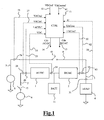
- the figure 1 schematically represents an uninterruptible power supply according to a mode of the invention and associated control means
- the figure 2 shows in more detail the units and the associated control functions of the control means.
- the figure 2 represents operation in normal mode.
- the figure 3 represents normal economy mode operation.
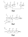
- the figure 4 represents the first current regulating unit of the first converter as well as the associated function.
- the figure 5 represents the second current regulating unit of the second converter as well as the associated function.
- the figure 6 represents a current processing unit in the load used in a particular embodiment.
- the figure 7 represents the first voltage regulator unit of the second converter as well as the associated function.
- the figure 8 represents the second voltage regulator unit of the second converter as well as the associated function.
- the figure 9 is a flowchart representative of the uninterrupted power supply method according to one embodiment.
- the uninterrupted power supply represented at figure 1 corresponds to a preferred embodiment of the invention of the double conversion type, that is to say comprising a first converter 1 of an AC voltage VACin1 in a DC voltage VDC, and a second reversible converter 2 of the DC voltage VDC in an AC voltage VACout on a power supply output 3 intended to be connected to an electrical load 4.
- the uninterruptible power supplies of the double conversion type are suitable, in particular, for the production of medium and high power electrical energy.
- the first converter is of the "PFC" type, that is to say allowing a correction of the power factor on a first input 5 to make this power factor tend towards the unit.
- the uninterrupted power supply comprises two inputs, the first input 5 being intended to be connected to a first source 6, also called normal network or in English "normal AC".
- the second input 7 is, for its part, intended to be connected to a second source 8, also called backup network or in English "bypass AC".
- the uninterruptible power supply also comprises a bypass and / or selection circuit 9 equipped with switch means 10 for, when operating in economic mode, directly coupling an input, in this case the second input 7, to the output 3.
- the uninterrupted power supply represented in figure 1 also comprises means for storing electrical energy, for example a battery 11 arranged between the first and the second converter.
- the uninterrupted power supply represented at figure 1 allows operation in two distinct modes: the normal mode and the economy mode.
- the load 4 is fed by the conversion chain comprising the first converter 1 and the second converter 2.
- the converters can be in a coupled state or in English "on line" , that is to say that the first converter 1 converts the AC voltage of the first input 5 into a DC voltage VDC, and the second converter 2 makes it possible to convert the DC voltage VDC into an alternating voltage VACout on the power output 3.
- the converters can also be in a state of autonomy in the case where the source connected to the first input no longer supplies energy or supplies energy outside certain tolerances. In this case, only the second converter is used to convert a DC voltage, the output of the latter being provided by a battery 11 or by a DC / DC conversion module comprising said battery 11.
- the switch means 10 are closed and the load is fed via the branch and / or selection circuit 9.
- the uninterrupted supply represented by FIG. figure 1 there are two inputs connected to two separate sources: a first source often referred to as a normal network and a second source often referred to as a back-up network.
- switching to economy mode corresponds to the selection of the second source and the coupling of this second source with the power output.
- the first source is decoupled from the first input by switch means 12.
- the uninterrupted power supply comprises a single input intended to be connected to a single source
- the transition to Economic is a derivation of this single input on the power output.
- the uninterrupted power supply represented at figure 1 comprises control means 13 for controlling the first converter 1 and the second converter 2 respectively via control outputs 14 and 15.
- the control of these converters can be achieved by current regulation using, for example, pulse width modulation techniques, also known in English as “pulse-width modulation”, or abbreviated as "PWM”.
- the control means are represented more precisely in the figures 2 and 3 .
- the figure 2 corresponds to normal mode operation, whereas the figure 3 corresponds to economic mode operation.
- the control means 13 comprise a set of units used during operation in normal mode during from which the input is decoupled from the supply output by the opening of the switching means 10 of the shunt and / or selection circuit 9.
- control means 13 are made so as to regulate, during operation in economic mode, the quality of the current on the input 7, while keeping the first converter stopped.
- control means 13 comprise switching means between the units, or at least part of said units, which are used during normal mode operation.
- switching means operation in economic mode can be envisaged using only at least a portion of the units provided for normal mode operation, ie without adding additional units which would be dedicated for operation in operation. economic mode.
- control means 13 comprise units associated with control functions, as well as switching means between a part of the set of units used during operation in normal mode.
- the set of units used during operation in normal mode comprises a first current regulating unit 21 of the first converter 1 equipped with a reference current input 22 and having the control output 14.
- a second current regulating unit 23 of the second converter is equipped with a reference current input 24 and comprises the control output 15.
- the first and second current regulation units allow the control of the first and second converters respectively.
- the first current regulating unit 21 is shown in more detail in the figure 4 . It comprises a comparator 101 between a reference current Iref1 on the input 22 and the value of the current I AC / DC at the input of the first converter, this value being available on a line 25.
- comparator we mean a module whose the function is to compare values, in this case current intensities, to restore a value corresponding to the difference or the difference between these two values.
- a comparator may also be called a subtractor.
- line 25 is connected to measuring means 26 of current I AC / DC at the input of the first converter.
- the output of the comparator is connected to a current regulator 102 making it possible to minimize the output value of the comparator 101, ie the difference between the reference current Iref1 and the value of the current I AC / DC, by determining a value
- the current regulator 102 may advantageously be a regulator with a minimum response time or a regulator of the "PID" type, that is to say having proportional, integral and derivative functions.
- An adder or adder 103 makes it possible to add the value obtained on an output 104 of the current regulator 102 with the value of the AC voltage VACin1 on the first input 5, the latter value being available on a line 27. This operation thus makes it possible to optimize the operation of the current regulator 102 by performing disturbance compensation. As shown in figure 1 the line 27 is connected to measuring means 28 of the AC voltage VACin1 on the first input 5.
- the output of the comparator 103 is, in turn, connected to the control output 14.
- the second current regulating unit 23 is shown in more detail in FIG. figure 5 . It comprises a comparator / summator 111 enabling, on the one hand, the sum of a reference current, Iref1 or Iref2, on the input 24 and a current in the load IC whose value is available on a line 29, and secondly, to determine the difference between the result of this sum and the value of a current I DC / AC output of the second converter available on a line 30. As shown in FIG. figure 1 lines 29 and 30 are connected to measuring means 31 and 32 respectively of the current IC in the load and the current I DC / AC output of the second converter.
- the output of the comparator / summator is connected to a current regulator 112 making it possible to minimize the output value of the comparator / summator 111 by generating a control signal on a control output 15.
- the current regulator 112 may advantageously be a regulator minimum response time or a regulator of the "PID" type, ie with proportional, integral and derivative functions.
- control means 13 may furthermore comprise a processing unit 181 of the current IC in the load 4.
- This unit may be installed upstream of the second current regulation unit 23, is on line 29.
- the processing unit 181 of the current IC comprises a fast Fourier transform module 151 making it possible to obtain a Fourier transform of the current in the load, a correction module 152 and an inverse Fourier transform module 153.
- the modified load current ICmod is sent to the second current regulation unit 23.
- bypass means can directly send the value of the unmodified load current to the second unit of current regulation 23.
- the processing unit 181 of the current IC thus makes it possible to minimize the reaction time of the second current regulation unit 23.
- control means 13 are made so as to regulate, during operation in economic mode, the quality of the current on the input 7 while maintaining the first converter stopped.
- the first current regulating unit is stopped.
- the set of units used during operation in normal mode further comprises a first voltage regulator unit 41 for regulating the DC voltage VDC between the two converters.
- This first voltage regulation unit is equipped with an output 42 for supplying a first reference current Iref1 and a synchronization input 43.
- a second voltage regulation unit 44 makes it possible to regulate the alternating voltage. VACout on the output 3.
- This second voltage regulating unit is equipped with an output 45 to provide a second reference current Iref2 and a synchronization input 46.
- the first voltage regulator unit 41 is shown in more detail in FIG. figure 7 . It comprises a multiplier 155 for generating the first reference current Iref1 from a control signal CdeDC available on a line 47, and a reference signal SIGref available on the synchronization input 43.
- the first unit 41 voltage regulator converts the control signal CdeDC, which is of continuous type in a reference current Iref1 of alternative type.
- the control signal CdeDC available on the line 47 is determined by a voltage regulator 132 whose function is to minimize the difference between the DC voltage VDC between the two converters and the value of a setpoint VDCref of said DC voltage.
- the voltage regulator 132 may advantageously be a regulator with minimum response time or a regulator of the "PID" type, that is to say having proportional, integral and derivative functions.
- the difference between the DC voltage VDC and the value of a reference VDCref of said DC voltage is determined by a comparator 131.
- comparator is meant a module whose function is to compare values, in this case voltages, to render a value corresponding to the difference or the difference between these two values.
- the value of the DC voltage VDC is available on the line 53 and the value of the reference VDCref of said voltage is available on the line 52. As shown in FIG. figure 1 the line 53 is connected to means 54 for measuring the DC voltage VDC between the two converters.
- the second voltage regulating unit 44 is shown in more detail in FIG. figure 8 . It comprises a multiplier 143 making it possible to multiply a setpoint value of the AC voltage VACout on the output 3 by a reference signal SIGref available on the synchronization input 46.
- the setpoint value of the AC voltage VACout is generally representative of an effective voltage and is available on a line 61. During operation in normal mode, a voltage setpoint is thus provided on the output 144 of this multiplier 143.
- the second voltage regulating unit 44 further comprises a comparator 141 between, on the one hand, the value of the voltage setpoint on the line 144, and on the other hand, the value of the AC voltage VACout on the power output, this value being available on a line 62.
- comparator means a module whose function is to compare values, in this case voltages, to restore a value corresponding to the difference or the difference between these two values.
- the line 62 is connected to measuring means 63 of the AC voltage VACout on the power output.
- the output of the comparator 141 is connected to a voltage regulator 142 whose output 45 is intended to provide the second reference current Iref2.
- the regulator 142 has the function of generating the second reference current Iref2 to obtain an alternating voltage VACout on the output 3 tending towards the voltage setpoint supplied on the output 144 of the multiplier 143, and this independently of the power variations of the load 4 connected to the output 3.
- the set of units used during operation in normal mode further comprises a first generator 71 of reference alternating signal equipped with an output 72 and connected via line 27 to the measuring means 28 of the voltage alternative on the first VACin1 entry.
- This first generator makes it possible to generate an alternative reference signal SIGrefl, on said output 72, in phase with the AC voltage on the first input VACin1.
- this reference signal SIGrefl is used, in the normal mode, to generate the first reference current Iref1 with the aid of the first voltage regulation unit 41.
- the set of units used during operation in normal mode further comprises a second reference signal generator 73 having an output 74 and connected via a line 75 to measuring means 76 of the AC voltage on the second VACin2 input.
- This second generator makes it possible to generate an alternating reference signal SIGref2, on said output 74, in phase with the AC voltage on the second input VACin2.
- This reference signal SIGref2 is used, in the normal mode, to generate the second reference current Iref2 by means of the second voltage regulation unit 44.
- control means 13 comprise switching means between at least a portion of the set of units used during normal mode operation.
- the switching means comprise a first switch 121 and a second switch 122 for, when operating in normal mode, connect the output 42 of the first voltage regulator unit 41 to the input 22 of the first current control unit 21, using the first switch 121, and connect the output 45 of the second voltage regulating unit 44 to the input 24 of the second current regulating unit 23 with the aid of the second switch 122.
- the first voltage regulation unit 41 supplies a first reference current Iref1 to the input of reference current 22 of the first current regulating unit 21, and the second voltage regulating unit 44 supplies a second reference current Iref2 to the reference current input 24 of the second current regulating unit 23.
- the regulation of each converter comprises an internal current regulation loop via the first and second current regulation units 21 and 23 respectively dedicated to the first and second converters.
- the regulation of each converter further comprises an external voltage regulation loop via the first and second voltage regulating units 41 and 44 respectively dedicated to the first and second converters.
- the first switch 121 and the second switch 122 switching means allow, during operation in economic mode, to connect the output 42 of the first voltage regulator unit 41 to an intermediate connection means 123 with the aid of the first switch 121, and to connect the input 24 of the second current regulating unit 23 to said intermediate connection means 123 with the second switch 122.
- the output 42 of the first voltage regulation unit 41 is connected to the input 24 of the second current regulation unit 23.
- the intermediate connection means 123 may be an electrically conductive element, as shown in FIGS. figures 2 and 3 . It can also be any software means for performing such a connection function.
- the second converter thus provides two functions simultaneously.
- the first function is to automatically recharge the batteries 11 by taking the second source 8, Also called a back-up network, a sinusoidal current with a power factor close to unity and a low harmonic distortion rate.
- the second function of the second converter is to generate, on the power output 3, a current for compensating both the harmonic current and the reactive current of the load.
- the second converter 2 thus provides the reactive and harmonic part of the current in the load.
- the active part of this current is, for its part, supplied by the second source 8. This active part is also used for the supply of energy necessary for powering the second converter and for auxiliaries arranged between the two converters, including the battery 11.
- the switching means comprise a third switch 131.
- the third switch makes it possible to connect the synchronization input 43 of the first voltage regulator unit 41 to the output 72 of the first generator 71.
- the third switch makes it possible to connect the synchronization input 43 of the first voltage regulation unit 41 to the output 74 of the second generator 73.
- the current on the input 7 of the uninterruptible power supply provided by the source 8 has few harmonics and its reactive part is minimized.
- the overall energy efficiency is improved by the fact that the first converter is stopped and the energy required for uninterruptible power supply is provided by the second source.
- the implementation of the invention does not require a control unit or regulation dedicated to operating in economic mode. Only at least a portion of the units dedicated to normal mode operation is used in the economy mode, using the switching means. This allows a great ease of implementation of uninterrupted power supplies, especially those of the double conversion type.
Landscapes
- Business, Economics & Management (AREA)
- Emergency Management (AREA)
- Engineering & Computer Science (AREA)
- Power Engineering (AREA)
- Stand-By Power Supply Arrangements (AREA)
- Rectifiers (AREA)
- Dc-Dc Converters (AREA)
- Direct Current Feeding And Distribution (AREA)
- Circuits Of Receivers In General (AREA)
Applications Claiming Priority (1)
| Application Number | Priority Date | Filing Date | Title |
|---|---|---|---|
| FR0703373A FR2916100B1 (fr) | 2007-05-11 | 2007-05-11 | Alimentation sans interruption et procede de mise en oeuvre de ladite alimentation |
Publications (2)
| Publication Number | Publication Date |
|---|---|
| EP1990893A1 true EP1990893A1 (de) | 2008-11-12 |
| EP1990893B1 EP1990893B1 (de) | 2010-03-03 |
Family
ID=38836164
Family Applications (1)
| Application Number | Title | Priority Date | Filing Date |
|---|---|---|---|
| EP20080354020 Active EP1990893B1 (de) | 2007-05-11 | 2008-03-14 | Unterbrechungsfreie Stromversorgung und Verfahren zur Umsetzung einer solchen Stromversorgung |
Country Status (7)
| Country | Link |
|---|---|
| US (1) | US7948118B2 (de) |
| EP (1) | EP1990893B1 (de) |
| AT (1) | ATE460001T1 (de) |
| DE (1) | DE602008000737D1 (de) |
| DK (1) | DK1990893T3 (de) |
| ES (1) | ES2339077T3 (de) |
| FR (1) | FR2916100B1 (de) |
Cited By (1)
| Publication number | Priority date | Publication date | Assignee | Title |
|---|---|---|---|---|
| EP3407454A1 (de) * | 2017-05-24 | 2018-11-28 | Commissariat A L'energie Atomique Et Aux Energies Alternatives | Schnittstellenvorrichtung zwischen einem allgemeinen stromnetz und einem lokalen stromnetz, die einen lokalen energieaustausch ermöglicht |
Families Citing this family (19)
| Publication number | Priority date | Publication date | Assignee | Title |
|---|---|---|---|---|
| US8084886B2 (en) * | 2006-03-28 | 2011-12-27 | Fujitsu Limited | Uninterruptible power supply apparatus |
| BRPI0910864A2 (pt) * | 2008-03-25 | 2016-05-17 | Delta Electronics Inc | sistema de conversor de potência que opera eficientemente por uma escala de condições de carga |
| JP2010115008A (ja) * | 2008-11-06 | 2010-05-20 | Tdk-Lambda Corp | 無停電電源装置 |
| US8422256B2 (en) * | 2010-07-30 | 2013-04-16 | General Electric Company | Control system for high-efficiency operation in parallel inverter installations |
| TWI477053B (zh) * | 2012-08-16 | 2015-03-11 | Delta Electronics Inc | 混合型直流交流轉換系統及其操作方法 |
| US9250639B2 (en) * | 2012-08-23 | 2016-02-02 | Honeywell International Inc. | Advanced energy management |
| EP2896108A1 (de) * | 2012-09-12 | 2015-07-22 | Schneider Electric IT Corporation | System und verfahren zur spannungsregelung in einer spannungsversorgung |
| WO2014098800A1 (en) * | 2012-12-18 | 2014-06-26 | Schneider Electric It Corporation | Method and apparatus for detecting failed capacitors in power devices |
| DK2941805T3 (da) | 2013-01-07 | 2020-02-17 | Schneider Electric It Corp | Strømforsyningsstyring |
| US10505367B2 (en) | 2013-08-21 | 2019-12-10 | Schneider Electric It Corporation | Apparatus and method for providing a power interface |
| CN105981252B (zh) * | 2013-12-23 | 2019-08-20 | 施耐德电气It公司 | 用于负载谐波抑制的系统和方法 |
| CN106030438B (zh) | 2013-12-31 | 2018-10-09 | 施耐德电气It公司 | 电网稳定的系统和方法 |
| US10566834B2 (en) * | 2014-04-04 | 2020-02-18 | Schneider Electric It Corporation | Systems and methods for quick power delivery mode changes |
| CN110651423B (zh) * | 2017-04-27 | 2023-02-28 | 逸节电子有限公司 | 用于使在电源中的逆变器的峰值功率需求最小化的设备 |
| EP3425782A1 (de) | 2017-07-06 | 2019-01-09 | ABB Schweiz AG | Usv-system mit betrieb im sparmodus |
| JP6608405B2 (ja) * | 2017-07-19 | 2019-11-20 | 矢崎総業株式会社 | 電圧変換ユニット |
| US10734821B2 (en) * | 2018-03-08 | 2020-08-04 | Saudi Arabian Oil Company | Power control system |
| US10790670B1 (en) | 2018-03-08 | 2020-09-29 | Zerobase Energy, Llc | Hybrid generator system and method with multi tasked power inverter |
| CN121283008A (zh) * | 2024-07-02 | 2026-01-06 | 施耐德电气It公司 | 平行模块化的ups系统 |
Citations (4)
| Publication number | Priority date | Publication date | Assignee | Title |
|---|---|---|---|---|
| US6201371B1 (en) * | 1998-08-07 | 2001-03-13 | Matsushita Electric Industrial Co., Ltd. | Uninterruptible power system |
| US6295215B1 (en) | 2000-04-06 | 2001-09-25 | Powerware Corporation | AC power supply apparatus with economy mode and methods of operation thereof |
| US20030184160A1 (en) * | 2002-03-28 | 2003-10-02 | Mitsubishi Denki Kabushiki Kaisha | Parallel operation method for an uninterruptible power supply apparatus |
| US20050201127A1 (en) * | 2004-03-09 | 2005-09-15 | Tracy John G. | Multi-mode uninterruptible power supplies and methods of operation thereof |
Family Cites Families (18)
| Publication number | Priority date | Publication date | Assignee | Title |
|---|---|---|---|---|
| US4763013A (en) * | 1987-09-21 | 1988-08-09 | American Telephone And Telegraph Company, At&T Bell Laboratories | Backup protection switch to prevent reverse power flow in a UPS |
| US5172009A (en) * | 1991-02-25 | 1992-12-15 | Regents Of The University Of Minnesota | Standby power supply with load-current harmonics neutralizer |
| US5612580A (en) * | 1995-10-10 | 1997-03-18 | Northrop Grumman Corporation | Uninterruptible power system |
| US6118676A (en) * | 1998-11-06 | 2000-09-12 | Soft Switching Technologies Corp. | Dynamic voltage sag correction |
| AU2002246920A1 (en) * | 2000-10-27 | 2002-08-06 | Emerson Electric Co. | Uninterruptible power supply |
| US6603672B1 (en) * | 2000-11-10 | 2003-08-05 | Ballard Power Systems Corporation | Power converter system |
| US20040084965A1 (en) * | 2002-10-22 | 2004-05-06 | Welches Richard Shaun | Hybrid variable speed generator/uninterruptible power supply power converter |
| US6906933B2 (en) * | 2002-11-01 | 2005-06-14 | Powerware Corporation | Power supply apparatus and methods with power-factor correcting bypass mode |
| CA2508728A1 (en) * | 2002-12-06 | 2004-06-24 | Electric Power Research Institute,Inc. | Uninterruptable power supply and generator system |
| US7070426B2 (en) * | 2003-06-09 | 2006-07-04 | Decell Jr George Raymond | Electric outlet child safety cap |
| US7939968B2 (en) * | 2004-08-31 | 2011-05-10 | American Power Conversion Corporation | Method and apparatus for providing uninterruptible power |
| US7148660B2 (en) * | 2004-09-30 | 2006-12-12 | General Electric Company | System and method for power conversion using semiconductor switches having reverse voltage withstand capability |
| US7391132B2 (en) * | 2004-12-03 | 2008-06-24 | Huei-Jung Chen | Methods and apparatus providing double conversion/series-parallel hybrid operation in uninterruptible power supplies |
| US7456520B2 (en) * | 2005-03-31 | 2008-11-25 | General Electric Company | Control system, method and product for uninterruptible power supply |
| US7566988B2 (en) * | 2005-06-14 | 2009-07-28 | Liebert Corporation | Method and apparatus for monitoring UPS power sources |
| US7508094B2 (en) * | 2006-03-17 | 2009-03-24 | Eaton Corporation | UPS systems having multiple operation modes and methods of operating same |
| US7649758B2 (en) * | 2006-11-30 | 2010-01-19 | Eaton Corporation | Power supply apparatus, methods and computer program products using D-Q domain based synchronization techniques |
| US7881079B2 (en) * | 2008-03-24 | 2011-02-01 | American Power Conversion Corporation | UPS frequency converter and line conditioner |
-
2007
- 2007-05-11 FR FR0703373A patent/FR2916100B1/fr not_active Expired - Fee Related
-
2008
- 2008-03-14 DK DK08354020T patent/DK1990893T3/da active
- 2008-03-14 ES ES08354020T patent/ES2339077T3/es active Active
- 2008-03-14 EP EP20080354020 patent/EP1990893B1/de active Active
- 2008-03-14 AT AT08354020T patent/ATE460001T1/de not_active IP Right Cessation
- 2008-03-14 DE DE200860000737 patent/DE602008000737D1/de active Active
- 2008-05-06 US US12/149,681 patent/US7948118B2/en active Active
Patent Citations (4)
| Publication number | Priority date | Publication date | Assignee | Title |
|---|---|---|---|---|
| US6201371B1 (en) * | 1998-08-07 | 2001-03-13 | Matsushita Electric Industrial Co., Ltd. | Uninterruptible power system |
| US6295215B1 (en) | 2000-04-06 | 2001-09-25 | Powerware Corporation | AC power supply apparatus with economy mode and methods of operation thereof |
| US20030184160A1 (en) * | 2002-03-28 | 2003-10-02 | Mitsubishi Denki Kabushiki Kaisha | Parallel operation method for an uninterruptible power supply apparatus |
| US20050201127A1 (en) * | 2004-03-09 | 2005-09-15 | Tracy John G. | Multi-mode uninterruptible power supplies and methods of operation thereof |
Cited By (2)
| Publication number | Priority date | Publication date | Assignee | Title |
|---|---|---|---|---|
| EP3407454A1 (de) * | 2017-05-24 | 2018-11-28 | Commissariat A L'energie Atomique Et Aux Energies Alternatives | Schnittstellenvorrichtung zwischen einem allgemeinen stromnetz und einem lokalen stromnetz, die einen lokalen energieaustausch ermöglicht |
| FR3066863A1 (fr) * | 2017-05-24 | 2018-11-30 | Commissariat A L'energie Atomique Et Aux Energies Alternatives | Dispositif d'interfacage entre un reseau electrique general et un reseau electrique local permettant un echange local d'energie |
Also Published As
| Publication number | Publication date |
|---|---|
| US20080278005A1 (en) | 2008-11-13 |
| DE602008000737D1 (de) | 2010-04-15 |
| ES2339077T3 (es) | 2010-05-14 |
| DK1990893T3 (da) | 2010-05-25 |
| EP1990893B1 (de) | 2010-03-03 |
| FR2916100B1 (fr) | 2009-08-14 |
| ATE460001T1 (de) | 2010-03-15 |
| US7948118B2 (en) | 2011-05-24 |
| FR2916100A1 (fr) | 2008-11-14 |
Similar Documents
| Publication | Publication Date | Title |
|---|---|---|
| EP1990893B1 (de) | Unterbrechungsfreie Stromversorgung und Verfahren zur Umsetzung einer solchen Stromversorgung | |
| EP0874440B1 (de) | Vorrichtung und Verfahren zur Stromversorugung von elektronischen Einrichtungen | |
| EP2718976B1 (de) | Photovoltaische ziegel mit serieller oder paralleler architektur | |
| FR3060230A1 (fr) | Procede de commande d'un dispositif de charge embarque sur un vehicule electrique ou hybride. | |
| EP0654887A1 (de) | Unterbrechungsfreie Stromversorgung mit gemeinsamem Nullleiter und Doppelaufwärtskonverter | |
| FR2974253A1 (fr) | Dispositif de charge d'une batterie d'un vehicule automobile a partir d'un reseau d'alimentation monophase, et procede de commande du dispositif | |
| EP2073340B1 (de) | Stromversorgungssystem für Satelliten | |
| EP0480846A1 (de) | Wechselstromenergieversorgungsanlage mit Notstromversorgung ausgestattet mit einem mit umkehrbarer Betriebsart arbeitendem Wechselrichter | |
| EP3604020B1 (de) | Kombinierte steuerung von zwei spannungsquellen | |
| EP2436074A1 (de) | System zur umgehung der zellen einer brennstoffzelle | |
| FR2824203A1 (fr) | Convertisseur d'alimentation electrique | |
| EP2400643A1 (de) | Steuerungsverfahren eines mehrphasig verschachtelten nullspannungsschaltenden Gleichstrom/Gleichstrom-Wandlers | |
| FR3026243A1 (fr) | Dispositif et procede de charge d'une batterie et d'alimentation d'une machine electrique a double convertisseur continu-continu | |
| FR3089721A1 (fr) | Dispositif de charge réversible pour véhicule automobile | |
| EP2655123A2 (de) | Vorrichtung und verfahren zur gleichstromwandlung im bordnetz eines kraftfahrzeuges | |
| FR3026242A1 (fr) | Dispositif combine de charge d'une batterie et d'alimentation electrique d'une machine electrique | |
| FR3006512A1 (fr) | Circuit de gestion d'energie d'un capteur autonome | |
| WO2024146983A1 (fr) | Systeme de batterie comportant des moyens de synchronisation de la tension et de regulation de courant avec un reseau d'alimentation electrique | |
| EP3323668B1 (de) | System und verfahren zur steuerung der unterbrechungsfreien stromversorgung im haushalt, die mit einem elektro- oder hybridfahrzeug verbunden ist | |
| WO2018202353A1 (fr) | Optimisation de chaînes photovoltaïques à bus partagé | |
| FR2999029A1 (fr) | Dispositif et procede de regulation de l'alimentation electrique d'un reseau ayant une source photovoltaique. | |
| WO2025181449A1 (fr) | Système hybride électrique d'alimentation d'équipements électriques d'un aéronef à partir d'une turbomachine | |
| FR2978308A1 (fr) | Chargeur de batterie embarque dans un vehicule automobile, a alimentation electrique continue | |
| WO2009004150A1 (fr) | Conditionneur d'energie | |
| FR3153294A1 (fr) | Systeme d’alimentation electrique comprenant une pile a combustible |
Legal Events
| Date | Code | Title | Description |
|---|---|---|---|
| PUAI | Public reference made under article 153(3) epc to a published international application that has entered the european phase |
Free format text: ORIGINAL CODE: 0009012 |
|
| AK | Designated contracting states |
Kind code of ref document: A1 Designated state(s): AT BE BG CH CY CZ DE DK EE ES FI FR GB GR HR HU IE IS IT LI LT LU LV MC MT NL NO PL PT RO SE SI SK TR |
|
| AX | Request for extension of the european patent |
Extension state: AL BA MK RS |
|
| 17P | Request for examination filed |
Effective date: 20081127 |
|
| AKX | Designation fees paid |
Designated state(s): AT BE BG CH CY CZ DE DK EE ES FI FR GB GR HR HU IE IS IT LI LT LU LV MC MT NL NO PL PT RO SE SI SK TR |
|
| GRAP | Despatch of communication of intention to grant a patent |
Free format text: ORIGINAL CODE: EPIDOSNIGR1 |
|
| GRAS | Grant fee paid |
Free format text: ORIGINAL CODE: EPIDOSNIGR3 |
|
| GRAA | (expected) grant |
Free format text: ORIGINAL CODE: 0009210 |
|
| AK | Designated contracting states |
Kind code of ref document: B1 Designated state(s): AT BE BG CH CY CZ DE DK EE ES FI FR GB GR HR HU IE IS IT LI LT LU LV MC MT NL NO PL PT RO SE SI SK TR |
|
| REG | Reference to a national code |
Ref country code: GB Ref legal event code: FG4D Free format text: NOT ENGLISH |
|
| REG | Reference to a national code |
Ref country code: CH Ref legal event code: EP |
|
| REG | Reference to a national code |
Ref country code: IE Ref legal event code: FG4D |
|
| REF | Corresponds to: |
Ref document number: 602008000737 Country of ref document: DE Date of ref document: 20100415 Kind code of ref document: P |
|
| REG | Reference to a national code |
Ref country code: ES Ref legal event code: FG2A Ref document number: 2339077 Country of ref document: ES Kind code of ref document: T3 |
|
| REG | Reference to a national code |
Ref country code: DK Ref legal event code: T3 |
|
| REG | Reference to a national code |
Ref country code: NL Ref legal event code: VDEP Effective date: 20100303 |
|
| PG25 | Lapsed in a contracting state [announced via postgrant information from national office to epo] |
Ref country code: NO Free format text: LAPSE BECAUSE OF FAILURE TO SUBMIT A TRANSLATION OF THE DESCRIPTION OR TO PAY THE FEE WITHIN THE PRESCRIBED TIME-LIMIT Effective date: 20100603 Ref country code: HR Free format text: LAPSE BECAUSE OF FAILURE TO SUBMIT A TRANSLATION OF THE DESCRIPTION OR TO PAY THE FEE WITHIN THE PRESCRIBED TIME-LIMIT Effective date: 20100303 Ref country code: LT Free format text: LAPSE BECAUSE OF FAILURE TO SUBMIT A TRANSLATION OF THE DESCRIPTION OR TO PAY THE FEE WITHIN THE PRESCRIBED TIME-LIMIT Effective date: 20100303 |
|
| LTIE | Lt: invalidation of european patent or patent extension |
Effective date: 20100303 |
|
| PG25 | Lapsed in a contracting state [announced via postgrant information from national office to epo] |
Ref country code: AT Free format text: LAPSE BECAUSE OF FAILURE TO SUBMIT A TRANSLATION OF THE DESCRIPTION OR TO PAY THE FEE WITHIN THE PRESCRIBED TIME-LIMIT Effective date: 20100303 Ref country code: LV Free format text: LAPSE BECAUSE OF FAILURE TO SUBMIT A TRANSLATION OF THE DESCRIPTION OR TO PAY THE FEE WITHIN THE PRESCRIBED TIME-LIMIT Effective date: 20100303 Ref country code: PL Free format text: LAPSE BECAUSE OF FAILURE TO SUBMIT A TRANSLATION OF THE DESCRIPTION OR TO PAY THE FEE WITHIN THE PRESCRIBED TIME-LIMIT Effective date: 20100303 Ref country code: SI Free format text: LAPSE BECAUSE OF FAILURE TO SUBMIT A TRANSLATION OF THE DESCRIPTION OR TO PAY THE FEE WITHIN THE PRESCRIBED TIME-LIMIT Effective date: 20100303 |
|
| PG25 | Lapsed in a contracting state [announced via postgrant information from national office to epo] |
Ref country code: CY Free format text: LAPSE BECAUSE OF FAILURE TO SUBMIT A TRANSLATION OF THE DESCRIPTION OR TO PAY THE FEE WITHIN THE PRESCRIBED TIME-LIMIT Effective date: 20100303 Ref country code: SE Free format text: LAPSE BECAUSE OF FAILURE TO SUBMIT A TRANSLATION OF THE DESCRIPTION OR TO PAY THE FEE WITHIN THE PRESCRIBED TIME-LIMIT Effective date: 20100303 Ref country code: GR Free format text: LAPSE BECAUSE OF FAILURE TO SUBMIT A TRANSLATION OF THE DESCRIPTION OR TO PAY THE FEE WITHIN THE PRESCRIBED TIME-LIMIT Effective date: 20100604 Ref country code: MC Free format text: LAPSE BECAUSE OF NON-PAYMENT OF DUE FEES Effective date: 20100331 Ref country code: RO Free format text: LAPSE BECAUSE OF FAILURE TO SUBMIT A TRANSLATION OF THE DESCRIPTION OR TO PAY THE FEE WITHIN THE PRESCRIBED TIME-LIMIT Effective date: 20100303 Ref country code: EE Free format text: LAPSE BECAUSE OF FAILURE TO SUBMIT A TRANSLATION OF THE DESCRIPTION OR TO PAY THE FEE WITHIN THE PRESCRIBED TIME-LIMIT Effective date: 20100303 Ref country code: NL Free format text: LAPSE BECAUSE OF FAILURE TO SUBMIT A TRANSLATION OF THE DESCRIPTION OR TO PAY THE FEE WITHIN THE PRESCRIBED TIME-LIMIT Effective date: 20100303 |
|
| PG25 | Lapsed in a contracting state [announced via postgrant information from national office to epo] |
Ref country code: BG Free format text: LAPSE BECAUSE OF FAILURE TO SUBMIT A TRANSLATION OF THE DESCRIPTION OR TO PAY THE FEE WITHIN THE PRESCRIBED TIME-LIMIT Effective date: 20100603 Ref country code: CZ Free format text: LAPSE BECAUSE OF FAILURE TO SUBMIT A TRANSLATION OF THE DESCRIPTION OR TO PAY THE FEE WITHIN THE PRESCRIBED TIME-LIMIT Effective date: 20100303 Ref country code: IS Free format text: LAPSE BECAUSE OF FAILURE TO SUBMIT A TRANSLATION OF THE DESCRIPTION OR TO PAY THE FEE WITHIN THE PRESCRIBED TIME-LIMIT Effective date: 20100703 Ref country code: SK Free format text: LAPSE BECAUSE OF FAILURE TO SUBMIT A TRANSLATION OF THE DESCRIPTION OR TO PAY THE FEE WITHIN THE PRESCRIBED TIME-LIMIT Effective date: 20100303 |
|
| PLBE | No opposition filed within time limit |
Free format text: ORIGINAL CODE: 0009261 |
|
| STAA | Information on the status of an ep patent application or granted ep patent |
Free format text: STATUS: NO OPPOSITION FILED WITHIN TIME LIMIT |
|
| 26N | No opposition filed |
Effective date: 20101206 |
|
| PG25 | Lapsed in a contracting state [announced via postgrant information from national office to epo] |
Ref country code: MT Free format text: LAPSE BECAUSE OF FAILURE TO SUBMIT A TRANSLATION OF THE DESCRIPTION OR TO PAY THE FEE WITHIN THE PRESCRIBED TIME-LIMIT Effective date: 20100303 |
|
| PG25 | Lapsed in a contracting state [announced via postgrant information from national office to epo] |
Ref country code: PT Free format text: LAPSE BECAUSE OF FAILURE TO SUBMIT A TRANSLATION OF THE DESCRIPTION OR TO PAY THE FEE WITHIN THE PRESCRIBED TIME-LIMIT Effective date: 20100803 Ref country code: LU Free format text: LAPSE BECAUSE OF NON-PAYMENT OF DUE FEES Effective date: 20100314 Ref country code: HU Free format text: LAPSE BECAUSE OF FAILURE TO SUBMIT A TRANSLATION OF THE DESCRIPTION OR TO PAY THE FEE WITHIN THE PRESCRIBED TIME-LIMIT Effective date: 20100904 |
|
| PG25 | Lapsed in a contracting state [announced via postgrant information from national office to epo] |
Ref country code: TR Free format text: LAPSE BECAUSE OF FAILURE TO SUBMIT A TRANSLATION OF THE DESCRIPTION OR TO PAY THE FEE WITHIN THE PRESCRIBED TIME-LIMIT Effective date: 20100303 |
|
| REG | Reference to a national code |
Ref country code: FR Ref legal event code: PLFP Year of fee payment: 9 |
|
| REG | Reference to a national code |
Ref country code: FR Ref legal event code: PLFP Year of fee payment: 10 |
|
| REG | Reference to a national code |
Ref country code: FR Ref legal event code: PLFP Year of fee payment: 11 |
|
| PGFP | Annual fee paid to national office [announced via postgrant information from national office to epo] |
Ref country code: DE Payment date: 20250327 Year of fee payment: 18 |
|
| PGFP | Annual fee paid to national office [announced via postgrant information from national office to epo] |
Ref country code: DK Payment date: 20250325 Year of fee payment: 18 Ref country code: FI Payment date: 20250325 Year of fee payment: 18 |
|
| PGFP | Annual fee paid to national office [announced via postgrant information from national office to epo] |
Ref country code: IE Payment date: 20250318 Year of fee payment: 18 |
|
| PGFP | Annual fee paid to national office [announced via postgrant information from national office to epo] |
Ref country code: BE Payment date: 20250325 Year of fee payment: 18 |
|
| PGFP | Annual fee paid to national office [announced via postgrant information from national office to epo] |
Ref country code: FR Payment date: 20250324 Year of fee payment: 18 |
|
| PGFP | Annual fee paid to national office [announced via postgrant information from national office to epo] |
Ref country code: IT Payment date: 20250321 Year of fee payment: 18 Ref country code: GB Payment date: 20250325 Year of fee payment: 18 |
|
| PGFP | Annual fee paid to national office [announced via postgrant information from national office to epo] |
Ref country code: ES Payment date: 20250415 Year of fee payment: 18 |
|
| PGFP | Annual fee paid to national office [announced via postgrant information from national office to epo] |
Ref country code: CH Payment date: 20250401 Year of fee payment: 18 |
|
| REG | Reference to a national code |
Ref country code: DE Ref legal event code: R081 Ref document number: 602008000737 Country of ref document: DE Owner name: SCHNEIDER ELECTRIC IT LTD., BALLYBRIT, IE Free format text: FORMER OWNER: MGE UPS SYSTEMS, SAINT-ISMIER, FR |
|
| REG | Reference to a national code |
Ref country code: FI Ref legal event code: PCE Owner name: SCHNEIDER ELECTRIC IT LIMITED, IE |
|
| REG | Reference to a national code |
Ref country code: CH Ref legal event code: R14 Free format text: ST27 STATUS EVENT CODE: U-0-0-R10-R14 (AS PROVIDED BY THE NATIONAL OFFICE) Effective date: 20260331 |
|
| REG | Reference to a national code |
Ref country code: GB Ref legal event code: 732E Free format text: REGISTERED BETWEEN 20260305 AND 20260311 |
|
| REG | Reference to a national code |
Ref country code: GB Ref legal event code: 732E Free format text: REGISTERED BETWEEN 20260409 AND 20260415 |