EP1990894A2 - Stator pour moteur électrique à aimants permanents utilisant des composés magnétiques doux - Google Patents
Stator pour moteur électrique à aimants permanents utilisant des composés magnétiques doux Download PDFInfo
- Publication number
- EP1990894A2 EP1990894A2 EP07024335A EP07024335A EP1990894A2 EP 1990894 A2 EP1990894 A2 EP 1990894A2 EP 07024335 A EP07024335 A EP 07024335A EP 07024335 A EP07024335 A EP 07024335A EP 1990894 A2 EP1990894 A2 EP 1990894A2
- Authority
- EP
- European Patent Office
- Prior art keywords
- stator
- winding
- recited
- core
- axial
- Prior art date
- Legal status (The legal status is an assumption and is not a legal conclusion. Google has not performed a legal analysis and makes no representation as to the accuracy of the status listed.)
- Granted
Links
Images


Classifications
-
- H—ELECTRICITY
- H02—GENERATION; CONVERSION OR DISTRIBUTION OF ELECTRIC POWER
- H02K—DYNAMO-ELECTRIC MACHINES
- H02K21/00—Synchronous motors having permanent magnets; Synchronous generators having permanent magnets
- H02K21/12—Synchronous motors having permanent magnets; Synchronous generators having permanent magnets with stationary armatures and rotating magnets
- H02K21/22—Synchronous motors having permanent magnets; Synchronous generators having permanent magnets with stationary armatures and rotating magnets with magnets rotating around the armatures, e.g. flywheel magnetos
- H02K21/222—Flywheel magnetos
-
- H—ELECTRICITY
- H02—GENERATION; CONVERSION OR DISTRIBUTION OF ELECTRIC POWER
- H02K—DYNAMO-ELECTRIC MACHINES
- H02K1/00—Details of the magnetic circuit
- H02K1/06—Details of the magnetic circuit characterised by the shape, form or construction
- H02K1/12—Stationary parts of the magnetic circuit
- H02K1/14—Stator cores with salient poles
- H02K1/146—Stator cores with salient poles consisting of a generally annular yoke with salient poles
- H02K1/148—Sectional cores
-
- H—ELECTRICITY
- H02—GENERATION; CONVERSION OR DISTRIBUTION OF ELECTRIC POWER
- H02K—DYNAMO-ELECTRIC MACHINES
- H02K21/00—Synchronous motors having permanent magnets; Synchronous generators having permanent magnets
- H02K21/12—Synchronous motors having permanent magnets; Synchronous generators having permanent magnets with stationary armatures and rotating magnets
- H02K21/24—Synchronous motors having permanent magnets; Synchronous generators having permanent magnets with stationary armatures and rotating magnets with magnets axially facing the armatures, e.g. hub-type cycle dynamos
-
- H—ELECTRICITY
- H02—GENERATION; CONVERSION OR DISTRIBUTION OF ELECTRIC POWER
- H02K—DYNAMO-ELECTRIC MACHINES
- H02K3/00—Details of windings
- H02K3/04—Windings characterised by the conductor shape, form or construction, e.g. with bar conductors
-
- Y—GENERAL TAGGING OF NEW TECHNOLOGICAL DEVELOPMENTS; GENERAL TAGGING OF CROSS-SECTIONAL TECHNOLOGIES SPANNING OVER SEVERAL SECTIONS OF THE IPC; TECHNICAL SUBJECTS COVERED BY FORMER USPC CROSS-REFERENCE ART COLLECTIONS [XRACs] AND DIGESTS
- Y02—TECHNOLOGIES OR APPLICATIONS FOR MITIGATION OR ADAPTATION AGAINST CLIMATE CHANGE
- Y02T—CLIMATE CHANGE MITIGATION TECHNOLOGIES RELATED TO TRANSPORTATION
- Y02T10/00—Road transport of goods or passengers
- Y02T10/60—Other road transportation technologies with climate change mitigation effect
- Y02T10/64—Electric machine technologies in electromobility
Definitions
- the present invention relates to an electric motor, and more particularly, to a stator for a radial-axial flux type motor or generator.
- DC motors can take two types of forms: DC motors or AC motors.
- DC motors have been developed and used extensively for a long period of time due to their high performance in motion and drive applications. However, with DC motors there are many maintenance and efficiency issues due to inclusion of slip rings and brushes that are needed to commutate these machines. With the more recent development of power electronics, new control technologies and machine topologies, great progress has been made to replace these DC machines in the variable speed drive area. AC motors are used to obtain better performance, reliability, improved maintenance characteristics, and overall lower costs. Extensive research and development has gone into developing AC machines that are suitable for drive applications and still match the drive characteristics of their DC counterparts.
- AC motors are designed for use with either polyphase or single-phase power systems.
- AC motors are typically divided into these categories: series, synchronous, and induction motors.
- Induction motors, single-phase or polyphase, are the most commonly used type of AC motor and the name is derived from the fact that AC voltages are induced in a rotor circuit by rotating in a magnetic field of a stator.
- induction machines are the dominant choice for both constant speed and variable speed drives.
- induction machines also have difficulties. For instance, since rotor windings are present in all induction machines, the rotor current produces rotor resistive losses, decreasing the efficiency of the motor, particularly at low power ratings, and, in some cases, causing cooling problems.
- hybrid axial-radial motors have been documented in U.S. Patent 7,034,422 and in a paper by A. G. Jack, "Permanent-Magnet Machines with Powdered Iron Cores and Prepressed Windings," IEEE Trans. Industry Applications, vol. 36, no. 4, pp 1077-1084, July/August 2000 .
- the stator winding is achieved through a toroidal type of winding, or a winding that is wrapped around a torrus-shaped stator.
- the '422 patent describes several HARM embodiments related to multiple stators and/or multiple rotors with the same or different machine types representing either the radial or axial portion of the HARMs.
- a stator of an electrical machine includes a plurality of stator segments disposed circumferentially about an axis, each segment having a generally wedge shaped core and a winding wound around the core, the winding being bent to have portions that are disposed on multiple planes.
- the core includes an elongated wedge tip portion aligned parallel to the axis and an outer radial face opposite to the tip portion.
- the multiple planes include at least one plane substantially normal to the axis and at least one plane tangential to the radial face.
- a method of operating a stator of an electrical machine that includes a plurality of stator segments disposed circumferentially about an axis, each segment including a generally wedge shaped core that has a radial face and a winding wound around the core, the winding being bent to have portions that are disposed on multiple planes, includes the step of providing electrical current to the winding to cause the portions to generate magnetic fluxes propagating in multiple directions normal to the multiple planes respectively.
- the multiple planes include at least one plane substantially normal to the axis and at least one plane tangential to the radial face.
- FIG. 1 shows a schematic partial cutaway view of a motor in accordance with one embodiment of the present invention.
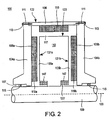
- FIG. 2 shows a schematic cross sectional view of the motor in FIG. 1 , taken along the line II-II.
- FIG. 3A shows a perspective view of a stator segment included in the motor of FIG. 1 .
- FIG. 3B shows an exploded view of the stator segment in FIG. 3A .
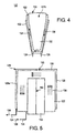
- FIG. 4 shows a schematic axial view of the stator segment in FIG. 3A .
- FIG. 5 shows a schematic side view of the stator segment in FIG. 3A .
- the preferred embodiments describe a winding and stator design for a radial-axial machine, or hybrid axial-radial machine, that includes at least one axial flux air gap and at least one radial flux air gap.
- the stator includes a plurality of separate electromagnetic core segments that induce two axial flux fields as well as a radial flux field.
- the segments are formed of soft magnetic composite electromagnetic material, or any other material allowing the conduction of magnetic flux in multiple directions, on more surfaces and thereby increasing the power and torque density of the machine.
- FIG. 1 shows a schematic partial cutaway view of a motor 100 in accordance with one embodiment of the present invention.
- FIG. 2 shows a schematic cross sectional view of the motor 100, taken along the line 11-11.
- the motor 100 referred to as an inside-out motor or out-rotor motor, includes an outer rotor 102 set outside of a stator 101.
- the motor 100 is preferably an axial-radial motor or a hybrid-axial-radial motor (HARM).
- HARM hybrid-axial-radial motor
- the rotor 102 includes three components, two axial rotor hubs 104a, 104b, and one radial rotor case 106.
- the radial rotor case 106 has a generally hollow cylindrical shell shape.
- Each of the axial rotor hubs 104a, 104b includes a circular disk and a hollow conical frustum located at the center portion of the disk.
- the axial hubs 104a, 104b are secured by suitable fasteners 111 to the radial rotor case 106 such that the circular disks of the hubs are in a spaced-apart relationship with each other.
- Circular tubes 113 are formed in the rotor hubs 104a, 104b, wherein the fasteners 111 pass through the tubes 113.
- Each of the rotor hubs 104a, 104b includes a center hole or passageway 107 through which a center spindle 109 passes.
- the spindle 109 has a generally elongated cylindrical shape and an axis that is disposed along the rotational axis 103 of the rotor 102. The diameter of the spindle 109 may vary along the rotational axis 103.
- the rotor hubs 104a, 104b are rotatably mounted on the spindle 109 by bearings 115.
- the stator 101 has a general ring shape and includes a plurality of stator segments 112 that are disposed circumferentially about the axis 103 around the center spindle 109 and secured in place with an epoxy resin, fasteners, locking features or any method that would maintain the mechanical integrity of the stator as required.
- Each stator segment 112 has a generally wedge shape, and each of the two principal wedge surfaces faces an adjacent stator segment 112.
- the elongated wedge tip portion 147 of the segment 112 (more specifically, the tip 147 of the core 128 in FIG. 3B ) is aligned substantially parallel to the rotational axis 103 of the rotor 102.
- Each segment has two wedge-shaped axial faces 131 a, 131 b and a radial face 133 disposed opposite to the tip portion 147. Further detailed description of the stator segments 112 will be given with reference to FIGS. 3A-5 .
- Axial permanent magnets 108a, 108b are secured to the inner axial (or, lateral) surfaces of the disks of the axial rotor hubs 104a, 104b, wherein the disks are disposed substantially normal to the axis 103.
- Each of the axial magnets 108a, 108b is a generally wedge-shaped comparable to the wedge-shaped profile of the axial faces 131 a, 131 b of the stator segment 112.
- the axial magnets 108a, 108b are arranged such that the tip portions 119a, 119b of the axial magnets point to the axis 103.
- the polarities of adjacent axial magnets, say 108a, disposed on a rotor hub surface are arranged to be opposite to each other, i.e., the axial magnets 108a are arranged to have alternating polarities.
- Each magnet 108a disposed on one axial rotor hub 104a has a counterpart axial magnet 108b disposed on the other axial rotor hub 104b, and the magnets 108a, 108b face the stator segment 112 with the same polarity.
- the axial component of the force imparted to the segment 112 due to the interaction between the magnet 108a and the segment 112 is equal and opposite to the axial component of the force due to the interaction between the magnet 108b and the segment 112.
- the magnets 108a, 108b can be secured to the rotor hubs 104a, 104b by various methods to ensure that the magnets will not move in high-speed rotational applications. For instance, high strength epoxies or glues are the preferred method. For another instance, sleeves or pockets formed in the inner surface of the rotor hubs 104a, 104b can also be used as a means to secure the magnets 108a, 108b to the rotor hubs. Segment to magnet pole ratios or otherwise known as slot-per-poie ratios can vary depending on the applications of the motor 100. In a preferred embodiment, there is a 0.75 Slot per Pole ratio, because it lowers the segment count for a more simple stator.
- the axial magnets 108a, 108b are respectively separated from the axial or lateral faces 131 a, 131 b of the stator segments 112 by axial air gaps 105a, 105b, i.e., the axial magnets 108a, 108b are in a spaced-apart relationship with the axial faces 131 a, 131 b of the segments (more specifically, with the axial faces 131 a, 131 b of the cores 130 of the segment as depicted in FIG. 3A ).
- An axial gap refers to a fluid filled volume, air or other fluid, where flux is conducted from the axial magnets 108a, 108b to the stator segments 112 or from the segments to the magnets thereacross.
- the axial flux crosses the axial air gaps 1 05a, 105b substantially parallel to the rotational axis 103 of the rotor 102.
- the axial magnets 108a, 108b interact with the magnetic flux generated by the segment 112 to impart rotational force to the rotor 102 during operation.
- the radial rotor case 106 being a generally cylindrical shell, houses radial permanent magnets 110 that face the circumferential or radial surface 133 of the stator segments 112.
- Each of the radial magnets 110 has a rectangular plate or rectangular cylindrical shape and is dimensioned to follow the radial surface 133 of the stator segment 112.
- the radial magnets 110 can be secured to the radial rotor case 106 by various methods to ensure that the magnets will not move in high-speed rotational applications.
- the polarities of adjacent radial magnets 110 are arranged to be opposite to each other, i.e., the radial permanent magnets are arranged to have alternating polarities. Also, the polarity of each radial magnet 110 is arranged such that a stator segment 112 surrounded by a radial magnet 110 and a neighboring pair of axial magnets 108a, 108b face the same polarities of the three magnets.
- the radial magnets 110 are separated from the radial faces 133 of the stator segments 112 by a radial air gap 117, i.e., the radial magnets 110 are in a spaced-apart relationship with the radial faces 133 of the segments 112.
- the radial magnets 110 interact with the magnetic flux generated by the segment 112 to impart rotational force to the rotor 102 during operation.
- the radial air gap 117 refers to a fluid filled volume, air or other fluid, where radial flux is conducted from the radial magnets 110 to the stator segments 112 or from the segments to the magnets thereacross
- the radial magnets 110 may be curved radially to follow the curvature of the radial faces 133.
- the radial flux crosses the radial air gap 117 substantially perpendicular to the rotational axis 103 of the rotor 102.
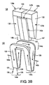
- FIG. 3A shows a perspective view of a stator segment 112 included in the motor 100.
- FiG. 3B shows an exploded view of the stator segment 112 in FIG. 3A .
- the stator segment 112 includes a stator segment core 128 and a winding 122 wound around the core 128.
- the core 128 includes a wedge portion 130 and a V-shaped protrusion or winding rest 132.
- each stator segment 112 is arranged in the motor 100 such that the winding rest 132 is in contact with winding rests of two adjacent stator segments 112.
- the core 128 can be formed in one integral body or created by joining two half-segment pieces 128a, 128b together with a bonding agent as shown in FIGS. 3A-3B and 5 .
- the wedge portion 130 is a cylinder having a generally wedge-shaped cross section.
- the elongated wedge tip portion 147 of the wedge portion 130 is aligned substantially parallel to the axis 103 ( FIG. 2 ).
- the wedge portion 130 also includes two principal wedge faces or side faces 135 and two axial faces 131a, 131b that are substantially parallel to each other and disposed substantially normal to the axis 103.
- the winding rest 132 provides axial winding surfaces 142a and radial winding surfaces 142b upon which the winding 122 rests.
- the winding rest 132 is a generally V-shaped protrusion when viewed in a direction normal to the axial face 131 b and formed on the side faces 135.
- the winding 122 includes three open loop portions: two axial portions 144a, 144b and a radial portion 144c.
- the axial portions 144a, 144b of the winding 122 which generate two axial magnetic fluxes along the directions 146a, 146b to respectively interact with the axial magnets 108a and 108b ( FIG. 2 ) during operation, rest on the axial winding surface 142a and the side face 135 of the wedge portion 130, while the radial portion 144c of the winding 122, which generates a radial magnetic flux along the direction 146c to interact with the radial magnets 110 ( FIG. 2 ) during operation, rests on the radial winding surface 142b and the side surface 135.
- the interaction between the magnets 108a, 108b, 110 with the fluxes generated by the winding 122 imparts rotational force to the rotor 102.
- FIG. 3B shows an exemplary current 136 flowing through the winding 122.
- the three flux vectors 146a, 146b, and 146c would propagate inward to both of the axial faces 131 a, 131 b and the radial surface 133 as well.
- the faces 131 a, 131 b and 133 are where the axial and radial fluxes are generated from the stator. Faces 131 a and 131 b conduct axial fluxes from the windings 122 or the magnets 133.
- the winding or winding loop 122 while looking at it from the axial face 131 b of the segment 128, is generally V-shaped because it follows the wedge-shaped profile of the segment core 128.
- the winding 122 is also generally C-shaped, when viewed in a direction normal to the side surface 135.
- One or more electrically conductive wires 124 such as copper wires, are wound around the wedge portion 130 and winding rest 132 to form the winding 122.
- the winding 122 is one that is bobbin wound or otherwise wound into a single planar winding loop and then bent in one or more places such that the open loop portions of the winding 122 define multiple planes, or equivalently are disposed on multiple planes.
- the open loop portions 144a, 144b, 144c of the winding 122 define three planes; two planes parallel to the axial faces 131 a, 131 b and one plane tangential to the radial face 133.
- the winding 122 induces fluxes in three major directions, 146a, 146b, and 146c, that are respectively normal to the three planes.
- the open loop portions 144a-144c of the winding 122 are arranged such that the fluxes propagating along the directions 146a, 146b, and 146c respectively cross the axial air gaps 105a, 105b, and 117 ( FIG. 2 ).
- all winding loop faces are arranged along the outer periphery of the stator 101, unlike the a more typical torroidal winding where the loops are wound such that they span the outer periphery to the inner periphery of the stator.
- the winding 122 can be formed, or wound in place such that it forms a shape that induces magnetic fluxes in multiple directions.
- the winding 122 can be comprised of multiple winding turns and multiple wires or multiple electrical current carrying conductors comprising each turn.
- the winding 122 is also known as a concentrated winding or a single tooth winding.
- the winding begins at the bottom left side of the segment core 128 and is carried around the axial and radial winding surfaces 142a, 142b on one side surface 135, back down the right side of the segment core and continuing the similar path on the opposite side surface 135 to complete one turn.
- This winding procedure is repeated to the specifications required for a motor design and the leads or wires 124 of the winding 122 are terminated on the same side or conversely on opposite sides of the segment core 128. For instance, in FIG. 3B , the wires 124 are terminated on the same side of the core 128.
- the same winding shape can be achieved by winding one or more electrically conductive wires around a jig or other apparatus such that a single loop area is formed to provide multiple planes as the wires are wound. Both ends of the wires 124 are coupled to an electrical power source 126 that transmits electrical current 136 in a single or poly phase through the winding 122.
- the wedge portion 130 carries magnetic flux analogous of the teeth in the stator of a conventional machine.
- the material between surfaces 142a, 142b and 132 carries flux normal to surface 160 to conduct flux between segments analogous to the conduction of flux through the stator back iron to adjacent teeth as in a conventional stator.
- the segment core 128 can be formed of soft magnetic composite electromagnetic materials (or other magnetically isotropic material), allowing the conduction of magnetic flux in multiple directions.
- soft magnetic permeable materials include Fe, SiFe, SiFeCo, NiFe or SiFeP, for example, and have a unique power loss, permeability and saturation level.
- the same general winding shape described above can be utilized without core material in an air core configuration. In this case the material described above as the core would become small or non-existent compared to the space consumed by the winding.
- Rare earth magnets like Neodymium Iron Boron (NdFeB) may be used in the rotor to achieve a higher efficiency and achieve the high air gap flux density and high torque density.
- the segment core128 is manufactured by filling the soft magnetic powder composite material into a die, pressing the material in the die, and then heat-treating at a temperature below the threshold of damaging the included insulating layer between the powder particles.
- the segment core 128 may be pressed in half pieces 128a, 128b and the final shape of the segment will be created by joining two half-segment pieces together with a bonding agent.
- the segment core 128 may be formed as a single integral body in a die.
- FIG. 4 shows a schematic axial view of the stator segment 112 in FIG. 3A , taken in a direction normal to the axial face 131b.
- the winding 122 is generally V-Shaped because it follows the wedge-shaped profile of the wedge portion 130.
- the axial face 131 b is generally a wedge shaped surface where the axial flux propagating in the direction 146b ( FIG. 3B ) is conducted across the axial airgap.
- the stator segment core 128, which includes the wedge portion 130 and winding rest 132, also possesses two axial faces 131 a, 131 b that are substantially parallel to each other.
- the electrical current 136 flowing through the winding 122 generates two fluxes propagating in opposite directions 146a and 146b ( FIG. 3B ).
- the magnetic fluxes would propagate inward to both of the axial faces 131 a, 131 b and the radial face 133 as well.
- the current 136 may flow in the opposite direction at a different point in time.
- the magnetic fluxes would propagate outward from both of the axial faces 131 a, 131 b and the radial face 133 as well.
- FIG. 5 shows a schematic side view of the stator segment unit in FIG. 3A , taken in a direction normal to the side face 135.
- two segment core halves 128a and 128b are joined together with a bonding agent to form the core body 128, wherein each segment half is manufactured by a conventional powder metallurgy technique.
- This bonding approach is chosen for this embodiment as an enabler of manufacturing for the Soft Magnetic Composite (SMC) powder compaction process.
- the segment core 128 can be formed in a single integral body.
- the bonding agent needs to be strong enough to hold the segment halves 128a, 128b as one integral body under a typical mechanical load for the application for which the motor 100 is designed.
- the segment halves 128a, 128b are joined at a surface 160 that is substantially parallel to the axial faces 131 a, 131 b and passes through the center of the segment 128.
- the halves 128a, 128b are symmetric with respect to the surface 160.
- the dimensions and shape of the segment core 128 are varied to meet the needs of a particular application.
- the electrically conductive wire(s) 124 is wound in such a way that a continuous loop is created around the segment core 128. If the winding 122 were to be removed from the segment core 128 and flattened, it would have rectangles forming a C-shape. As discussed above, while looking at the winding 122 from the side surface 135 of the core 128, the winding 122 is formed by repeatedly making turns to the specifications required for a motor design, wherein each turn begins at the bottom left side of the segment core 128 and is carried around the axial and radial winding surfaces 142a, 142b on one side surface 135, back down the right side of the segment core and continuing the similar path on the opposite side surface 135. The winding 122 is then pressed into place after or during the winding process such that they do not protrude past any of the surfaces of the segment core 128. The winding 122 may be held in place with an encapsulation material before final assembly.
- the exemplary embodiment 100 has been described as a motor.
- the embodiment 100 may be used as generator, i.e., electrical current can be generated and transmitted through the wires 104 when the rotor 102 is rotated with respect to the stator 101 by an external force.
Landscapes
- Engineering & Computer Science (AREA)
- Power Engineering (AREA)
- Iron Core Of Rotating Electric Machines (AREA)
- Insulation, Fastening Of Motor, Generator Windings (AREA)
Applications Claiming Priority (1)
| Application Number | Priority Date | Filing Date | Title |
|---|---|---|---|
| US11/747,451 US7755244B2 (en) | 2007-05-11 | 2007-05-11 | Stator for permanent magnet electric motor using soft magnetic composites |
Publications (3)
| Publication Number | Publication Date |
|---|---|
| EP1990894A2 true EP1990894A2 (fr) | 2008-11-12 |
| EP1990894A3 EP1990894A3 (fr) | 2016-05-11 |
| EP1990894B1 EP1990894B1 (fr) | 2021-07-14 |
Family
ID=39711948
Family Applications (1)
| Application Number | Title | Priority Date | Filing Date |
|---|---|---|---|
| EP07024335.7A Active EP1990894B1 (fr) | 2007-05-11 | 2007-12-14 | Stator pour moteur électrique à aimants permanents utilisant des composés magnétiques doux |
Country Status (3)
| Country | Link |
|---|---|
| US (1) | US7755244B2 (fr) |
| EP (1) | EP1990894B1 (fr) |
| CA (1) | CA2615111C (fr) |
Cited By (11)
| Publication number | Priority date | Publication date | Assignee | Title |
|---|---|---|---|---|
| CN107710569A (zh) * | 2015-04-08 | 2018-02-16 | 凌力尔特实验室股份有限公司 | 改进的多通道的电动马达/发电机 |
| US10256680B2 (en) | 2012-03-20 | 2019-04-09 | Linear Labs, LLC | Multi-tunnel electric motor/generator |
| US10263480B2 (en) | 2012-03-20 | 2019-04-16 | Linear Labs, LLC | Brushless electric motor/generator |
| US10284029B2 (en) | 2012-03-20 | 2019-05-07 | Linear Labs, LLC | Brushed electric motor/generator |
| US10447103B2 (en) | 2015-06-28 | 2019-10-15 | Linear Labs, LLC | Multi-tunnel electric motor/generator |
| US10476362B2 (en) | 2015-06-28 | 2019-11-12 | Linear Labs, LLC | Multi-tunnel electric motor/generator segment |
| CN111756125A (zh) * | 2020-05-21 | 2020-10-09 | 东南大学 | 一种轴向磁通电机定子 |
| US11159076B2 (en) | 2015-10-20 | 2021-10-26 | Linear Labs, Inc. | Circumferential flux electric machine with field weakening mechanisms and methods of use |
| US11218046B2 (en) | 2012-03-20 | 2022-01-04 | Linear Labs, Inc. | DC electric motor/generator with enhanced permanent magnet flux densities |
| US11277062B2 (en) | 2019-08-19 | 2022-03-15 | Linear Labs, Inc. | System and method for an electric motor/generator with a multi-layer stator/rotor assembly |
| US11309778B2 (en) | 2016-09-05 | 2022-04-19 | Linear Labs, Inc. | Multi-tunnel electric motor/generator |
Families Citing this family (49)
| Publication number | Priority date | Publication date | Assignee | Title |
|---|---|---|---|---|
| CN1734881A (zh) * | 2005-06-29 | 2006-02-15 | 陆孝庭 | 无刷旋转电动机 |
| US7439713B2 (en) * | 2006-09-20 | 2008-10-21 | Pratt & Whitney Canada Corp. | Modulation control of power generation system |
| BRPI0813185B1 (pt) * | 2007-07-09 | 2023-12-19 | Clearwater Holdings, Ltd | Máquina eletromagnética giratória |
| FR2926935B1 (fr) * | 2008-01-30 | 2012-06-08 | Tecddis | Machine electrique a flux axial et a aimants permanents |
| US10038349B2 (en) | 2008-08-15 | 2018-07-31 | Millennial Research Corporation | Multi-phase modular coil element for electric motor and generator |
| EP2340602B1 (fr) | 2008-09-26 | 2019-01-02 | Clearwater Holdings, Ltd. | Machine motrice à aimants permanents |
| JP5272831B2 (ja) * | 2009-03-19 | 2013-08-28 | 株式会社豊田中央研究所 | 回転電機 |
| US8242660B2 (en) | 2009-11-16 | 2012-08-14 | G+ Powertec Ltd. | AC generator |
| US9154024B2 (en) | 2010-06-02 | 2015-10-06 | Boulder Wind Power, Inc. | Systems and methods for improved direct drive generators |
| MX2013001081A (es) * | 2010-07-27 | 2013-08-21 | Kil Bong Song | Motor de armadura segmentada. |
| DE102010060482B4 (de) * | 2010-11-10 | 2017-07-13 | Binova Gmbh | Elektrischer Scheibenläufermotor und Elektrofahrrad oder Pedelec mit einem Scheibenläufermotor |
| CN106300851B (zh) | 2011-04-12 | 2019-12-17 | 巨石风力股份有限公司 | 气隙控制系统和方法 |
| TWI443258B (zh) | 2011-10-12 | 2014-07-01 | Ind Tech Res Inst | 旋轉動能輸出裝置 |
| US11146123B2 (en) * | 2012-02-03 | 2021-10-12 | Green Ray Technologies, Llc | Electric machines with energizable and non-energizerable U-shaped stator segments |
| CN104285363A (zh) | 2012-06-06 | 2015-01-14 | 尼得科电机有限公司 | 具有采用间隔开的极片的辐条式外转子的电机 |
| US10476324B2 (en) * | 2012-07-06 | 2019-11-12 | Persimmon Technologies Corporation | Hybrid field electric motor |
| CN102842974B (zh) | 2012-08-03 | 2015-06-03 | 埃塞克科技有限公司 | 横向磁通发电机 |
| US9559559B2 (en) | 2012-09-24 | 2017-01-31 | Eocycle Technologies Inc. | Transverse flux electrical machine stator with stator skew and assembly thereof |
| CA2829812A1 (fr) | 2012-10-17 | 2014-04-17 | Eocycle Technologies Inc. | Rotor de machine electrique a flux transversal |
| US10505412B2 (en) * | 2013-01-24 | 2019-12-10 | Clearwater Holdings, Ltd. | Flux machine |
| KR101492172B1 (ko) * | 2013-03-20 | 2015-02-11 | 전자부품연구원 | 일체형 권선을 활용한 반경 방향 및 축 방향 자속 일체형 모터 |
| WO2014176554A2 (fr) * | 2013-04-26 | 2014-10-30 | Millennial Research Corporation | Élément de bobine modulaire multiphase pour un moteur électrique et un générateur |
| EP2994408A4 (fr) * | 2013-05-06 | 2017-01-25 | Otis Elevator Company | Noyau de stator de moteur lineaire pour ascenseur autopropulse |
| WO2015130331A1 (fr) * | 2014-02-27 | 2015-09-03 | C&C Technologies Llc | Dispositif électromécanique et procédés de fabrication pour différentes applications |
| WO2015137790A2 (fr) * | 2014-03-14 | 2015-09-17 | Алдан Асанович САПАРГАЛИЕВ | Embrayage à induction à vecteurs multiples et machine électrique |
| KR101597965B1 (ko) * | 2014-07-02 | 2016-02-29 | 전자부품연구원 | 복합 자속을 이용한 모터 |
| CA2954469C (fr) | 2014-07-23 | 2023-03-21 | Clearwater Holdings, Ltd | Machine a flux |
| JP6402739B2 (ja) * | 2016-04-19 | 2018-10-10 | マツダ株式会社 | 回転電機 |
| US11159077B2 (en) | 2016-07-03 | 2021-10-26 | Reza Nasirizarandi | Hybrid hysteresis motor |
| CN108736602B (zh) * | 2017-04-14 | 2021-05-14 | 台达电子工业股份有限公司 | 轴向磁通电机 |
| JP7052017B2 (ja) | 2017-09-08 | 2022-04-11 | クリアウォーター ホールディングス,リミテッド | 蓄電を改善するシステム及び方法 |
| WO2019084568A1 (fr) | 2017-10-29 | 2019-05-02 | Clearwater Holdings, Ltd. | Machines électromagnétiques modulaires et leurs procédés d'utilisation et de fabrication |
| CN113366729B (zh) * | 2018-10-16 | 2024-07-26 | 康明斯公司 | 电机结构及工艺 |
| CN110224562B (zh) * | 2019-06-21 | 2024-08-09 | 赵滟玺 | 一种具有轴向径向多方向立体磁通路的新型节能电机 |
| US20220045559A1 (en) * | 2019-12-02 | 2022-02-10 | Linear Labs, Inc. | Segmented stator for a permanent magnet electric machine having a fractional-slot concentrated winding |
| US12341393B2 (en) * | 2019-08-26 | 2025-06-24 | Linear Labs, Inc. | System for an electrical motor with a segmented rotor and a segmented stator |
| US12374951B2 (en) * | 2019-08-26 | 2025-07-29 | Linear Labs, Inc. | System for an electrical motor with a segmented rotor and a segmented stator |
| US11502570B2 (en) * | 2019-08-26 | 2022-11-15 | Linear Labs, Inc. | Multi-tunnel electric machine |
| US12149141B2 (en) * | 2019-08-26 | 2024-11-19 | Linear Labs, Inc. | System for an electrical motor with coil assemblies and external radial magnetic elements |
| US11502564B2 (en) * | 2020-04-03 | 2022-11-15 | Mitsubishi Electric Research Laboratories, Inc. | Multi-layer axial and radial flux vernier permanent magnet motor |
| FR3110783B1 (fr) * | 2020-05-19 | 2022-04-22 | Conductix Wampfler France | Dispositif d’enroulement/déroulement d’un lien |
| CN111585363B (zh) * | 2020-06-12 | 2024-11-26 | 河北工业大学 | 一种软磁复合材料定子电机及其冷却方法 |
| US20220069681A1 (en) * | 2020-08-26 | 2022-03-03 | Linear Labs, Inc. | Method for winding a heavy gauge toroidal coil of an electric machine |
| US20230361637A1 (en) | 2020-09-16 | 2023-11-09 | National Research Council Of Canada | Electric machines with enhanced electromagnetic interaction |
| US11817752B2 (en) | 2021-04-01 | 2023-11-14 | Hamilton Sundstrand Corporation | Hybrid axial/radial electric motor |
| WO2023225363A1 (fr) | 2022-05-19 | 2023-11-23 | Linear Labs, Inc. | Système et procédé de commande de moteurs électriques à couple élevé et à grande vitesse |
| US12506372B2 (en) * | 2022-06-21 | 2025-12-23 | Board Of Regents, The University Of Texas System | High torque density 3D flux segmented-rotor switched reluctance machine |
| US11909280B1 (en) * | 2022-07-29 | 2024-02-20 | Edge Power Systems, LLC | Modular electrical generator/electric motor assembly, and method of using same |
| US12407204B2 (en) * | 2023-02-01 | 2025-09-02 | Rtx Corporation | Electric machine having rotor with integrated fan |
Family Cites Families (20)
| Publication number | Priority date | Publication date | Assignee | Title |
|---|---|---|---|---|
| AUPM827094A0 (en) * | 1994-09-20 | 1994-10-13 | Queensland Railways | Open stator axial flux electric motor |
| JPH08223885A (ja) * | 1995-02-15 | 1996-08-30 | Olympus Optical Co Ltd | ディスク駆動用モータ |
| US5894902A (en) * | 1996-09-05 | 1999-04-20 | The United States Of America As Represented By The Secretary Of The Navy | Self-propelled wheel for wheeled vehicles |
| SE518110C2 (sv) * | 1999-12-23 | 2002-08-27 | Hoeganaes Ab | Stator och rotor för en elektrisk maskin |
| US6791222B1 (en) * | 2002-04-30 | 2004-09-14 | Wavecrest Laboratories, Llc | Rotary electric motor having at least two axially air gaps separating stator and rotor segments |
| US6891306B1 (en) * | 2002-04-30 | 2005-05-10 | Wavecrest Laboratories, Llc. | Rotary electric motor having both radial and axial air gap flux paths between stator and rotor segments |
| US7034422B2 (en) * | 2002-05-24 | 2006-04-25 | Virginia Tech Intellectual Properties, Inc. | Radial-axial electromagnetic flux electric motor, coaxial electromagnetic flux electric motor, and rotor for same |
| JP4003058B2 (ja) * | 2002-07-17 | 2007-11-07 | 株式会社富士通ゼネラル | 誘導電動機 |
| JP2004153977A (ja) * | 2002-11-01 | 2004-05-27 | Hitachi Ltd | モータ |
| WO2005022738A2 (fr) * | 2003-01-31 | 2005-03-10 | Light Engineering, Inc. | Dispositif electrique efficace a grande vitesse utilisant des materiaux a faibles pertes |
| US6924574B2 (en) * | 2003-05-30 | 2005-08-02 | Wisconsin Alumni Research Foundation | Dual-rotor, radial-flux, toroidally-wound, permanent-magnet machine |
| US7155804B2 (en) * | 2003-09-17 | 2007-01-02 | Moog Inc. | Method of forming an electric motor |
| US7105975B2 (en) * | 2003-10-06 | 2006-09-12 | Light Engineering, Inc. | Efficient axial airgap electric machine having a frontiron |
| US7005764B2 (en) * | 2003-12-29 | 2006-02-28 | Petersen Technology Corporation | Electrodynamic apparatus and method of manufacture |
| US20050162034A1 (en) * | 2004-01-22 | 2005-07-28 | Wavecrest Laboratories, Inc. | Soft magnetic composites |
| US6956307B2 (en) * | 2004-03-08 | 2005-10-18 | Amsted Industries Incorporated | Soft magnetic composite powder metal cores |
| JP4370958B2 (ja) * | 2004-03-26 | 2009-11-25 | トヨタ自動車株式会社 | 回転電機 |
| US7148782B2 (en) * | 2004-04-26 | 2006-12-12 | Light Engineering, Inc. | Magnetic core for stationary electromagnetic devices |
| KR100585682B1 (ko) * | 2005-01-10 | 2006-06-07 | 엘지전자 주식회사 | 왕복동식 모터의 고정자 및 그 제조 방법 |
| US7554241B2 (en) * | 2006-03-31 | 2009-06-30 | Rao Dantam K | Three-gapped motor with outer rotor and stationary shaft |
-
2007
- 2007-05-11 US US11/747,451 patent/US7755244B2/en active Active - Reinstated
- 2007-12-14 EP EP07024335.7A patent/EP1990894B1/fr active Active
- 2007-12-17 CA CA2615111A patent/CA2615111C/fr active Active
Non-Patent Citations (1)
| Title |
|---|
| None * |
Cited By (21)
| Publication number | Priority date | Publication date | Assignee | Title |
|---|---|---|---|---|
| US11374442B2 (en) | 2012-03-20 | 2022-06-28 | Linear Labs, LLC | Multi-tunnel electric motor/generator |
| US11218046B2 (en) | 2012-03-20 | 2022-01-04 | Linear Labs, Inc. | DC electric motor/generator with enhanced permanent magnet flux densities |
| US10256680B2 (en) | 2012-03-20 | 2019-04-09 | Linear Labs, LLC | Multi-tunnel electric motor/generator |
| US10263480B2 (en) | 2012-03-20 | 2019-04-16 | Linear Labs, LLC | Brushless electric motor/generator |
| US10284029B2 (en) | 2012-03-20 | 2019-05-07 | Linear Labs, LLC | Brushed electric motor/generator |
| US10439452B2 (en) | 2012-03-20 | 2019-10-08 | Linear Labs, LLC | Multi-tunnel electric motor/generator |
| US11218038B2 (en) | 2012-03-20 | 2022-01-04 | Linear Labs, Inc. | Control system for an electric motor/generator |
| US11387692B2 (en) | 2012-03-20 | 2022-07-12 | Linear Labs, Inc. | Brushed electric motor/generator |
| CN111509873B (zh) * | 2015-04-08 | 2022-10-04 | 凌力尔特实验室股份有限公司 | 改进的多通道的电动马达/发电机 |
| CN111509873A (zh) * | 2015-04-08 | 2020-08-07 | 凌力尔特实验室股份有限公司 | 改进的多通道的电动马达/发电机 |
| CN107710569B (zh) * | 2015-04-08 | 2020-04-14 | 凌力尔特实验室股份有限公司 | 改进的多通道的电动马达/发电机 |
| CN107710569A (zh) * | 2015-04-08 | 2018-02-16 | 凌力尔特实验室股份有限公司 | 改进的多通道的电动马达/发电机 |
| EP3281285A4 (fr) * | 2015-04-08 | 2018-12-05 | Linear Labs, Inc. | Moteur/générateur électrique multi-tunnel amélioré |
| US11258320B2 (en) | 2015-06-28 | 2022-02-22 | Linear Labs, Inc. | Multi-tunnel electric motor/generator |
| US10476362B2 (en) | 2015-06-28 | 2019-11-12 | Linear Labs, LLC | Multi-tunnel electric motor/generator segment |
| US10447103B2 (en) | 2015-06-28 | 2019-10-15 | Linear Labs, LLC | Multi-tunnel electric motor/generator |
| US11159076B2 (en) | 2015-10-20 | 2021-10-26 | Linear Labs, Inc. | Circumferential flux electric machine with field weakening mechanisms and methods of use |
| US11309778B2 (en) | 2016-09-05 | 2022-04-19 | Linear Labs, Inc. | Multi-tunnel electric motor/generator |
| US11277062B2 (en) | 2019-08-19 | 2022-03-15 | Linear Labs, Inc. | System and method for an electric motor/generator with a multi-layer stator/rotor assembly |
| CN111756125B (zh) * | 2020-05-21 | 2021-07-27 | 东南大学 | 一种轴向磁通电机定子 |
| CN111756125A (zh) * | 2020-05-21 | 2020-10-09 | 东南大学 | 一种轴向磁通电机定子 |
Also Published As
| Publication number | Publication date |
|---|---|
| EP1990894A3 (fr) | 2016-05-11 |
| CA2615111A1 (fr) | 2008-11-11 |
| EP1990894B1 (fr) | 2021-07-14 |
| CA2615111C (fr) | 2011-03-15 |
| US7755244B2 (en) | 2010-07-13 |
| US20080278020A1 (en) | 2008-11-13 |
Similar Documents
| Publication | Publication Date | Title |
|---|---|---|
| EP1990894B1 (fr) | Stator pour moteur électrique à aimants permanents utilisant des composés magnétiques doux | |
| US20240380256A1 (en) | Segmented stator for a permanent magnet electric machine having a fractional-slot concentrated winding | |
| CN100490279C (zh) | 具有轴向磁通的多极电动机/发电机 | |
| CN103329401B (zh) | 用于具有低损耗磁性材料的电动马达或发电机的定子及其制造方法 | |
| AU2011303910B2 (en) | Rotor for modulated pole machine | |
| EP2523311A1 (fr) | Moteur sans balai du type à entrefer axial | |
| US12021467B2 (en) | Reluctance synchronous machines without permanent magnets | |
| JP2009531006A (ja) | 電気機械 | |
| US20070108850A1 (en) | Linear electrical machine for electric power generation or motive drive | |
| CN106716781B (zh) | 具有低的槽漏磁的电机器 | |
| WO2005006522A9 (fr) | Machine electrique lineaire pour generation de courant electrique ou entrainement moteur | |
| US20220045582A1 (en) | Method of manufacturing a three-dimensional flux structure for circumferential flux machines | |
| Pan et al. | Design and analysis of a novel transverse-flux tubular linear machine with gear-shaped teeth structure | |
| US20160056671A1 (en) | Flux switching modulated pole machine | |
| KR101048055B1 (ko) | 코어에 슬릿을 형성한 횡자속 전기기기 | |
| US9755465B2 (en) | Method for manufacturing a rotor of a synchronous reluctance motor, a rotor of a synchronous reluctance motor, and a synchronous reluctance motor | |
| TW201141010A (en) | Stator element for a modulated pole machine | |
| JP6485073B2 (ja) | 回転電機 | |
| CN103595150B (zh) | 具有磁通增强器的电机 | |
| JP2004304995A (ja) | 励磁機、界磁機、およびそれを用いた電動機 | |
| US20220069681A1 (en) | Method for winding a heavy gauge toroidal coil of an electric machine | |
| KR20130033137A (ko) | 고효율 전기모터, 고효율 전기 발전기 | |
| WO2014118603A2 (fr) | Procédé et générateur de moteur destinés à produire une énergie électrique | |
| CN106575892B (zh) | 用于磁阻机的可高极数地构成的转子 | |
| JP2006238612A (ja) | 電動機の分割型固定子およびその製造方法 |
Legal Events
| Date | Code | Title | Description |
|---|---|---|---|
| PUAI | Public reference made under article 153(3) epc to a published international application that has entered the european phase |
Free format text: ORIGINAL CODE: 0009012 |
|
| AK | Designated contracting states |
Kind code of ref document: A2 Designated state(s): AT BE BG CH CY CZ DE DK EE ES FI FR GB GR HU IE IS IT LI LT LU LV MC MT NL PL PT RO SE SI SK TR |
|
| AX | Request for extension of the european patent |
Extension state: AL BA HR MK RS |
|
| 17P | Request for examination filed |
Effective date: 20101112 |
|
| RAP1 | Party data changed (applicant data changed or rights of an application transferred) |
Owner name: UQM TECHNOLOGIES, INC. |
|
| PUAL | Search report despatched |
Free format text: ORIGINAL CODE: 0009013 |
|
| AK | Designated contracting states |
Kind code of ref document: A3 Designated state(s): AT BE BG CH CY CZ DE DK EE ES FI FR GB GR HU IE IS IT LI LT LU LV MC MT NL PL PT RO SE SI SK TR |
|
| AX | Request for extension of the european patent |
Extension state: AL BA HR MK RS |
|
| RIC1 | Information provided on ipc code assigned before grant |
Ipc: H02K 21/24 20060101ALI20160406BHEP Ipc: H02K 1/14 20060101AFI20160406BHEP Ipc: H02K 21/22 20060101ALI20160406BHEP Ipc: H02K 3/04 20060101ALI20160406BHEP |
|
| AKX | Designation fees paid |
Designated state(s): AT BE BG CH CY CZ DE DK EE ES FI FR GB GR HU IE IS IT LI LT LU LV MC MT NL PL PT RO SE SI SK TR |
|
| AXX | Extension fees paid |
Extension state: RS Extension state: HR Extension state: AL Extension state: BA Extension state: MK |
|
| STAA | Information on the status of an ep patent application or granted ep patent |
Free format text: STATUS: EXAMINATION IS IN PROGRESS |
|
| 17Q | First examination report despatched |
Effective date: 20181011 |
|
| RAP1 | Party data changed (applicant data changed or rights of an application transferred) |
Owner name: DANFOSS POWER SOLUTIONS (US) COMPANY |
|
| GRAP | Despatch of communication of intention to grant a patent |
Free format text: ORIGINAL CODE: EPIDOSNIGR1 |
|
| STAA | Information on the status of an ep patent application or granted ep patent |
Free format text: STATUS: GRANT OF PATENT IS INTENDED |
|
| INTG | Intention to grant announced |
Effective date: 20210201 |
|
| GRAS | Grant fee paid |
Free format text: ORIGINAL CODE: EPIDOSNIGR3 |
|
| GRAA | (expected) grant |
Free format text: ORIGINAL CODE: 0009210 |
|
| STAA | Information on the status of an ep patent application or granted ep patent |
Free format text: STATUS: THE PATENT HAS BEEN GRANTED |
|
| AK | Designated contracting states |
Kind code of ref document: B1 Designated state(s): AT BE BG CH CY CZ DE DK EE ES FI FR GB GR HU IE IS IT LI LT LU LV MC MT NL PL PT RO SE SI SK TR |
|
| REG | Reference to a national code |
Ref country code: GB Ref legal event code: FG4D |
|
| REG | Reference to a national code |
Ref country code: IE Ref legal event code: FG4D |
|
| REG | Reference to a national code |
Ref country code: DE Ref legal event code: R096 Ref document number: 602007061222 Country of ref document: DE |
|
| REG | Reference to a national code |
Ref country code: AT Ref legal event code: REF Ref document number: 1411417 Country of ref document: AT Kind code of ref document: T Effective date: 20210815 |
|
| REG | Reference to a national code |
Ref country code: SE Ref legal event code: TRGR |
|
| REG | Reference to a national code |
Ref country code: FI Ref legal event code: FGE |
|
| REG | Reference to a national code |
Ref country code: LT Ref legal event code: MG9D |
|
| REG | Reference to a national code |
Ref country code: NL Ref legal event code: MP Effective date: 20210714 |
|
| REG | Reference to a national code |
Ref country code: AT Ref legal event code: MK05 Ref document number: 1411417 Country of ref document: AT Kind code of ref document: T Effective date: 20210714 |
|
| PG25 | Lapsed in a contracting state [announced via postgrant information from national office to epo] |
Ref country code: ES Free format text: LAPSE BECAUSE OF FAILURE TO SUBMIT A TRANSLATION OF THE DESCRIPTION OR TO PAY THE FEE WITHIN THE PRESCRIBED TIME-LIMIT Effective date: 20210714 Ref country code: NL Free format text: LAPSE BECAUSE OF FAILURE TO SUBMIT A TRANSLATION OF THE DESCRIPTION OR TO PAY THE FEE WITHIN THE PRESCRIBED TIME-LIMIT Effective date: 20210714 Ref country code: PT Free format text: LAPSE BECAUSE OF FAILURE TO SUBMIT A TRANSLATION OF THE DESCRIPTION OR TO PAY THE FEE WITHIN THE PRESCRIBED TIME-LIMIT Effective date: 20211115 Ref country code: LT Free format text: LAPSE BECAUSE OF FAILURE TO SUBMIT A TRANSLATION OF THE DESCRIPTION OR TO PAY THE FEE WITHIN THE PRESCRIBED TIME-LIMIT Effective date: 20210714 Ref country code: BG Free format text: LAPSE BECAUSE OF FAILURE TO SUBMIT A TRANSLATION OF THE DESCRIPTION OR TO PAY THE FEE WITHIN THE PRESCRIBED TIME-LIMIT Effective date: 20211014 Ref country code: AT Free format text: LAPSE BECAUSE OF FAILURE TO SUBMIT A TRANSLATION OF THE DESCRIPTION OR TO PAY THE FEE WITHIN THE PRESCRIBED TIME-LIMIT Effective date: 20210714 |
|
| PG25 | Lapsed in a contracting state [announced via postgrant information from national office to epo] |
Ref country code: PL Free format text: LAPSE BECAUSE OF FAILURE TO SUBMIT A TRANSLATION OF THE DESCRIPTION OR TO PAY THE FEE WITHIN THE PRESCRIBED TIME-LIMIT Effective date: 20210714 Ref country code: LV Free format text: LAPSE BECAUSE OF FAILURE TO SUBMIT A TRANSLATION OF THE DESCRIPTION OR TO PAY THE FEE WITHIN THE PRESCRIBED TIME-LIMIT Effective date: 20210714 Ref country code: GR Free format text: LAPSE BECAUSE OF FAILURE TO SUBMIT A TRANSLATION OF THE DESCRIPTION OR TO PAY THE FEE WITHIN THE PRESCRIBED TIME-LIMIT Effective date: 20211015 |
|
| REG | Reference to a national code |
Ref country code: DE Ref legal event code: R097 Ref document number: 602007061222 Country of ref document: DE |
|
| PG25 | Lapsed in a contracting state [announced via postgrant information from national office to epo] |
Ref country code: DK Free format text: LAPSE BECAUSE OF FAILURE TO SUBMIT A TRANSLATION OF THE DESCRIPTION OR TO PAY THE FEE WITHIN THE PRESCRIBED TIME-LIMIT Effective date: 20210714 |
|
| PLBE | No opposition filed within time limit |
Free format text: ORIGINAL CODE: 0009261 |
|
| STAA | Information on the status of an ep patent application or granted ep patent |
Free format text: STATUS: NO OPPOSITION FILED WITHIN TIME LIMIT |
|
| PG25 | Lapsed in a contracting state [announced via postgrant information from national office to epo] |
Ref country code: SK Free format text: LAPSE BECAUSE OF FAILURE TO SUBMIT A TRANSLATION OF THE DESCRIPTION OR TO PAY THE FEE WITHIN THE PRESCRIBED TIME-LIMIT Effective date: 20210714 Ref country code: RO Free format text: LAPSE BECAUSE OF FAILURE TO SUBMIT A TRANSLATION OF THE DESCRIPTION OR TO PAY THE FEE WITHIN THE PRESCRIBED TIME-LIMIT Effective date: 20210714 Ref country code: EE Free format text: LAPSE BECAUSE OF FAILURE TO SUBMIT A TRANSLATION OF THE DESCRIPTION OR TO PAY THE FEE WITHIN THE PRESCRIBED TIME-LIMIT Effective date: 20210714 Ref country code: CZ Free format text: LAPSE BECAUSE OF FAILURE TO SUBMIT A TRANSLATION OF THE DESCRIPTION OR TO PAY THE FEE WITHIN THE PRESCRIBED TIME-LIMIT Effective date: 20210714 |
|
| 26N | No opposition filed |
Effective date: 20220419 |
|
| PG25 | Lapsed in a contracting state [announced via postgrant information from national office to epo] |
Ref country code: MC Free format text: LAPSE BECAUSE OF FAILURE TO SUBMIT A TRANSLATION OF THE DESCRIPTION OR TO PAY THE FEE WITHIN THE PRESCRIBED TIME-LIMIT Effective date: 20210714 |
|
| REG | Reference to a national code |
Ref country code: CH Ref legal event code: PL |
|
| REG | Reference to a national code |
Ref country code: BE Ref legal event code: MM Effective date: 20211231 |
|
| PG25 | Lapsed in a contracting state [announced via postgrant information from national office to epo] |
Ref country code: LU Free format text: LAPSE BECAUSE OF NON-PAYMENT OF DUE FEES Effective date: 20211214 Ref country code: IE Free format text: LAPSE BECAUSE OF NON-PAYMENT OF DUE FEES Effective date: 20211214 |
|
| PG25 | Lapsed in a contracting state [announced via postgrant information from national office to epo] |
Ref country code: BE Free format text: LAPSE BECAUSE OF NON-PAYMENT OF DUE FEES Effective date: 20211231 |
|
| PG25 | Lapsed in a contracting state [announced via postgrant information from national office to epo] |
Ref country code: LI Free format text: LAPSE BECAUSE OF NON-PAYMENT OF DUE FEES Effective date: 20211231 Ref country code: CH Free format text: LAPSE BECAUSE OF NON-PAYMENT OF DUE FEES Effective date: 20211231 |
|
| PG25 | Lapsed in a contracting state [announced via postgrant information from national office to epo] |
Ref country code: HU Free format text: LAPSE BECAUSE OF FAILURE TO SUBMIT A TRANSLATION OF THE DESCRIPTION OR TO PAY THE FEE WITHIN THE PRESCRIBED TIME-LIMIT; INVALID AB INITIO Effective date: 20071214 Ref country code: CY Free format text: LAPSE BECAUSE OF FAILURE TO SUBMIT A TRANSLATION OF THE DESCRIPTION OR TO PAY THE FEE WITHIN THE PRESCRIBED TIME-LIMIT Effective date: 20210714 |
|
| P01 | Opt-out of the competence of the unified patent court (upc) registered |
Effective date: 20230621 |
|
| PG25 | Lapsed in a contracting state [announced via postgrant information from national office to epo] |
Ref country code: TR Free format text: LAPSE BECAUSE OF FAILURE TO SUBMIT A TRANSLATION OF THE DESCRIPTION OR TO PAY THE FEE WITHIN THE PRESCRIBED TIME-LIMIT Effective date: 20210714 |
|
| PG25 | Lapsed in a contracting state [announced via postgrant information from national office to epo] |
Ref country code: MT Free format text: LAPSE BECAUSE OF FAILURE TO SUBMIT A TRANSLATION OF THE DESCRIPTION OR TO PAY THE FEE WITHIN THE PRESCRIBED TIME-LIMIT Effective date: 20210714 |
|
| PGFP | Annual fee paid to national office [announced via postgrant information from national office to epo] |
Ref country code: DE Payment date: 20251104 Year of fee payment: 19 |
|
| PGFP | Annual fee paid to national office [announced via postgrant information from national office to epo] |
Ref country code: GB Payment date: 20251114 Year of fee payment: 19 |
|
| PGFP | Annual fee paid to national office [announced via postgrant information from national office to epo] |
Ref country code: IT Payment date: 20251121 Year of fee payment: 19 Ref country code: FI Payment date: 20251211 Year of fee payment: 19 |
|
| PGFP | Annual fee paid to national office [announced via postgrant information from national office to epo] |
Ref country code: FR Payment date: 20251124 Year of fee payment: 19 |
|
| PGFP | Annual fee paid to national office [announced via postgrant information from national office to epo] |
Ref country code: SE Payment date: 20251112 Year of fee payment: 19 |