EP1990909A2 - Regelungsverfahren für ein Motorregelmodul - Google Patents
Regelungsverfahren für ein Motorregelmodul Download PDFInfo
- Publication number
- EP1990909A2 EP1990909A2 EP08163332A EP08163332A EP1990909A2 EP 1990909 A2 EP1990909 A2 EP 1990909A2 EP 08163332 A EP08163332 A EP 08163332A EP 08163332 A EP08163332 A EP 08163332A EP 1990909 A2 EP1990909 A2 EP 1990909A2
- Authority
- EP
- European Patent Office
- Prior art keywords
- current
- voltage
- motor
- triac
- control module
- Prior art date
- Legal status (The legal status is an assumption and is not a legal conclusion. Google has not performed a legal analysis and makes no representation as to the accuracy of the status listed.)
- Withdrawn
Links
- 238000000034 method Methods 0.000 title claims abstract description 41
- 238000005259 measurement Methods 0.000 claims abstract description 51
- 230000010355 oscillation Effects 0.000 claims abstract description 18
- 230000007704 transition Effects 0.000 claims description 16
- 238000012360 testing method Methods 0.000 claims description 5
- 230000003247 decreasing effect Effects 0.000 claims 1
- 238000010304 firing Methods 0.000 description 22
- 238000001514 detection method Methods 0.000 description 17
- 230000006870 function Effects 0.000 description 17
- 230000001939 inductive effect Effects 0.000 description 9
- 238000012544 monitoring process Methods 0.000 description 8
- 125000006850 spacer group Chemical group 0.000 description 8
- 238000010586 diagram Methods 0.000 description 7
- 238000004382 potting Methods 0.000 description 6
- 238000004364 calculation method Methods 0.000 description 5
- 230000007423 decrease Effects 0.000 description 4
- 238000004519 manufacturing process Methods 0.000 description 4
- 238000005070 sampling Methods 0.000 description 4
- 230000003321 amplification Effects 0.000 description 3
- 230000008859 change Effects 0.000 description 3
- 239000008393 encapsulating agent Substances 0.000 description 3
- 239000004519 grease Substances 0.000 description 3
- 238000002955 isolation Methods 0.000 description 3
- 239000000463 material Substances 0.000 description 3
- 230000007935 neutral effect Effects 0.000 description 3
- 238000003199 nucleic acid amplification method Methods 0.000 description 3
- 230000008569 process Effects 0.000 description 3
- 238000007493 shaping process Methods 0.000 description 3
- XBBRGUHRZBZMPP-UHFFFAOYSA-N 1,2,3-trichloro-4-(2,4,6-trichlorophenyl)benzene Chemical group ClC1=CC(Cl)=CC(Cl)=C1C1=CC=C(Cl)C(Cl)=C1Cl XBBRGUHRZBZMPP-UHFFFAOYSA-N 0.000 description 2
- JOYRKODLDBILNP-UHFFFAOYSA-N Ethyl urethane Chemical compound CCOC(N)=O JOYRKODLDBILNP-UHFFFAOYSA-N 0.000 description 2
- XUIMIQQOPSSXEZ-UHFFFAOYSA-N Silicon Chemical compound [Si] XUIMIQQOPSSXEZ-UHFFFAOYSA-N 0.000 description 2
- 230000008901 benefit Effects 0.000 description 2
- 238000012937 correction Methods 0.000 description 2
- 238000010292 electrical insulation Methods 0.000 description 2
- 238000001914 filtration Methods 0.000 description 2
- 238000011990 functional testing Methods 0.000 description 2
- 238000000227 grinding Methods 0.000 description 2
- 230000000737 periodic effect Effects 0.000 description 2
- 238000012545 processing Methods 0.000 description 2
- 230000001681 protective effect Effects 0.000 description 2
- 230000004044 response Effects 0.000 description 2
- 229910052710 silicon Inorganic materials 0.000 description 2
- 239000010703 silicon Substances 0.000 description 2
- 238000012935 Averaging Methods 0.000 description 1
- 239000004593 Epoxy Substances 0.000 description 1
- 230000005355 Hall effect Effects 0.000 description 1
- 238000009825 accumulation Methods 0.000 description 1
- 239000000654 additive Substances 0.000 description 1
- 230000000996 additive effect Effects 0.000 description 1
- 239000003990 capacitor Substances 0.000 description 1
- 238000006243 chemical reaction Methods 0.000 description 1
- 230000001447 compensatory effect Effects 0.000 description 1
- 238000010276 construction Methods 0.000 description 1
- 230000001351 cycling effect Effects 0.000 description 1
- 238000013461 design Methods 0.000 description 1
- 239000000428 dust Substances 0.000 description 1
- 230000005669 field effect Effects 0.000 description 1
- 230000036039 immunity Effects 0.000 description 1
- 239000012212 insulator Substances 0.000 description 1
- 238000012986 modification Methods 0.000 description 1
- 230000004048 modification Effects 0.000 description 1
- 230000002093 peripheral effect Effects 0.000 description 1
- 229920001296 polysiloxane Polymers 0.000 description 1
- 230000000135 prohibitive effect Effects 0.000 description 1
- 239000002356 single layer Substances 0.000 description 1
- 238000005476 soldering Methods 0.000 description 1
Images


Classifications
-
- H—ELECTRICITY
- H02—GENERATION; CONVERSION OR DISTRIBUTION OF ELECTRIC POWER
- H02M—APPARATUS FOR CONVERSION BETWEEN AC AND AC, BETWEEN AC AND DC, OR BETWEEN DC AND DC, AND FOR USE WITH MAINS OR SIMILAR POWER SUPPLY SYSTEMS; CONVERSION OF DC OR AC INPUT POWER INTO SURGE OUTPUT POWER; CONTROL OR REGULATION THEREOF
- H02M5/00—Conversion of AC power input into AC power output, e.g. for change of voltage, for change of frequency, for change of number of phases
- H02M5/02—Conversion of AC power input into AC power output, e.g. for change of voltage, for change of frequency, for change of number of phases without intermediate conversion into DC
- H02M5/04—Conversion of AC power input into AC power output, e.g. for change of voltage, for change of frequency, for change of number of phases without intermediate conversion into DC by static converters
- H02M5/22—Conversion of AC power input into AC power output, e.g. for change of voltage, for change of frequency, for change of number of phases without intermediate conversion into DC by static converters using discharge tubes with control electrode or semiconductor devices with control electrode
- H02M5/25—Conversion of AC power input into AC power output, e.g. for change of voltage, for change of frequency, for change of number of phases without intermediate conversion into DC by static converters using discharge tubes with control electrode or semiconductor devices with control electrode using devices of a thyratron or thyristor type requiring extinguishing means
- H02M5/257—Conversion of AC power input into AC power output, e.g. for change of voltage, for change of frequency, for change of number of phases without intermediate conversion into DC by static converters using discharge tubes with control electrode or semiconductor devices with control electrode using devices of a thyratron or thyristor type requiring extinguishing means using semiconductor devices only
- H02M5/2573—Conversion of AC power input into AC power output, e.g. for change of voltage, for change of frequency, for change of number of phases without intermediate conversion into DC by static converters using discharge tubes with control electrode or semiconductor devices with control electrode using devices of a thyratron or thyristor type requiring extinguishing means using semiconductor devices only with control circuit
- H02M5/2576—Conversion of AC power input into AC power output, e.g. for change of voltage, for change of frequency, for change of number of phases without intermediate conversion into DC by static converters using discharge tubes with control electrode or semiconductor devices with control electrode using devices of a thyratron or thyristor type requiring extinguishing means using semiconductor devices only with control circuit with digital control
-
- H—ELECTRICITY
- H02—GENERATION; CONVERSION OR DISTRIBUTION OF ELECTRIC POWER
- H02K—DYNAMO-ELECTRIC MACHINES
- H02K11/00—Structural association of dynamo-electric machines with electric components or with devices for shielding, monitoring or protection
- H02K11/30—Structural association with control circuits or drive circuits
- H02K11/33—Drive circuits, e.g. power electronics
-
- H—ELECTRICITY
- H02—GENERATION; CONVERSION OR DISTRIBUTION OF ELECTRIC POWER
- H02P—CONTROL OR REGULATION OF ELECTRIC MOTORS, ELECTRIC GENERATORS OR DYNAMO-ELECTRIC CONVERTERS; CONTROLLING TRANSFORMERS, REACTORS OR CHOKE COILS
- H02P25/00—Arrangements or methods for the control of AC motors characterised by the kind of AC motor or by structural details
- H02P25/02—Arrangements or methods for the control of AC motors characterised by the kind of AC motor or by structural details characterised by the kind of motor
- H02P25/10—Commutator motors, e.g. repulsion motors
- H02P25/14—Universal motors
-
- H—ELECTRICITY
- H02—GENERATION; CONVERSION OR DISTRIBUTION OF ELECTRIC POWER
- H02K—DYNAMO-ELECTRIC MACHINES
- H02K7/00—Arrangements for handling mechanical energy structurally associated with dynamo-electric machines, e.g. structural association with mechanical driving motors or auxiliary dynamo-electric machines
- H02K7/14—Structural association with mechanical loads, e.g. with hand-held machine tools or fans
- H02K7/145—Hand-held machine tool
Definitions
- Example embodiments in general relate to a motor control module and control methodologies for controlling operation of a motor in an associated electrical device such as a power tool.
- motors are controlled by dedicated analog or digital circuitry controlling the motor for a given application.
- a dedicated circuit may be required to control a given motor utilized in an application for an electrical device such as a power saw application, while another dedicated circuit may be required to control a different motor utilized in another power tool application such as a drill application.
- the dedicated analog or digital control circuit is typically constructed of different components. These components often have differing values, tolerances and/or control software to create a unique operational characteristic profile for a given motor and/or given motor application.
- Example embodiments are directed to a motor control module, which may implement a number of control methodologies to control operation of a motor in an electrical device, such as a tool motor of a corded power tool.
- the module includes a controller and a triac for controlling current to the given tool motor.
- the module can implement a plurality of control methodologies, including methodologies related to synchronizing the module to the AC input signal, estimating average current flowing through the triac, compensating for amplifier offset to improve accuracy of current measurements in the module, and providing speed measurement and control for the tool motor using principles of hysteresis in a comparator of the controller.
- the controller is configured to calibrate an oscillation calibration register therein.
- example embodiments are directed to control methodologies implemented by an electronic circuit within a motor control module of an electronic device.
- the electronic device may be a corded power tool having a tool motor powered by an AC source voltage for driving a work piece or accessory of the power tool.
- the example embodiments hereafter describe control methodologies performed by the circuit within the control module as related to and including, but not limited to: a method of detecting triac conduction following triac firing in the circuit, a method of detecting zero crosses of the AC waveform supplied to the power tool.
- the inventors initially provide an overview of an example power device with control module, and an example block diagram of the control module's electronics.
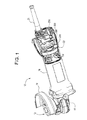
- FIG. 1 is a partial plan view of a power tool illustrating a control module within a housing of the tool, in accordance with an example embodiment.
- power tool 10 is shown embodied as a rotary, corded power tool 10, it being understood that the example embodiments are applicable to power tools other than rotary, corded power tools.
- power tool 10 is shown as an angle grinder powered by AC line power via a power cord 21.
- the angle grinder 10 includes a knurled clamp nut 12 within an accessory guard 14 for receiving a tool workpiece or accessory powered by the tool motor.
- the accessory may be a rotary accessory such as grinding disc (not shown).
- the grinding disc is attachable via a spindle to gear case 16, which is secured to tool housing 18.
- Tool housing 18 is shown with part of the outer shell removed, so as to illustrate a universal control module 100 ('control module') in proximate relationship to a magnetic collar 22 and a commutator ring 24 of a motor armature 20.
- the control module 100 is designed for controlling the operation of a plurality of motors and/or configured for a plurality of different motor applications (e.g. different power tools).
- an auxiliary board 200 supporting a pick-up coil assembly 250 and a variable speed dial wheel 270.
- the auxiliary board 200 may be included within the tool housing 18.
- One function of the auxiliary board 200 is it allows custom configuration of pick-up coil and variable speed dial as dictated by power tool design requirements.
- the pick-up coil assembly 250 is attachable to the auxiliary board 200 and configured to detect motor speed.
- the variable speed dial wheel 270 is operable by the user in order to set and/or change to the desired motor speed.
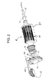
- FIG. 2 is an isometric view of selected components of the tool motor within the power tool to illustrate the relation of the control module, pick-up coil assembly, auxiliary board and speed dial, in accordance with an example embodiment.
- FIG. 2 illustrates the relationship between the auxiliary board 200 and its components (pick-up coil assembly 250 and speed dial 270), the control module 100 and the tool motor 15, which may be comprised of a tool motor armature 20 rotating within a tool motor field 30.
- the auxiliary board 200, pick-up coil assembly 250 and dial wheel 270 may be collectively referred to as an 'auxiliary circuit board assembly.
- the auxiliary circuit board assembly is attached to the control module 100 of FIG. 1 , for example, with the control module 100 being adapted to control operation of the tool motor.
- the tool motor armature 20 includes the magnetic collar 22 attachable via armature shaft 29 to the commutator ring 24 of the motor armature 20.
- the motor armature 20 output is translated to the gear case 16 via ball bearing 27 and spindle 28.
- Multiple magnets may be provided on the magnetic collar 22 of the motor armature 20.
- the magnetic field from the magnets is picked up by the pick-up coil assembly 250 to give an accurate reading of motor speed.
- the complete tool motor 15 consists of tool motor armature 20 rotating within tool motor field 30.
- the auxiliary board 200 may also include the variable speed dial wheel 270, which acts as a potentiometer as is known in the art.
- a portion of the dial wheel 270 may include a plurality of rigid detents which sit on points of a leaf spring, so as to provide aural feedback to the user.
- the detents contact the leaf spring to provide a tactile feedback to the user. This also serves to prevent the dial wheel 270 from moving during any tool vibration. Additionally, the use of detents may prevent the user from inadvertently changing speed, providing a readily discernible tactile feedback to the user.
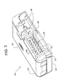
- FIG. 3 is an isometric view of the control module 100 in accordance with an example embodiment.
- the control module 100 includes a top cover 110, a bottom cover 120, a spacer 130 and a printed circuit board 140 (not shown in FIG. 3 ).
- the top cover 110 may be made of a material that provides heat sinking for active power components within the control module 100, and may be cast for that function, for example.
- the bottom cover 120 may be configured to support control module 100 interior components and to permit potting so as to create a sealed enclosure. Additionally, the bottom cover 120 provides an area of electrical insulation for an active power device within the control module 100.
- the spacer 130 may be configured to hold through-hole electronic components within the control module 100 in place, such as during assembly of the control module 100.
- the control module 100 also may include a fastener 115 (e.g., a screw) that fastens the top cover 110 to a nut (not shown) within the module 100.
- the fastener 115 may be fastened to an active power device such as a switch, a triac, electronic valve, etc., within control module 100.
- the top and bottom covers 110, 120 may therefore be secured together via a single fastener 115 such as a screw and nut assembly.
- the control module 100 also includes a pair of quick-connect power tabs 150 and an input/output connector 160 connected to the printed circuit board 140.
- the quick connect power tabs 150 are sequenced to the control module 100 and may be of a different size and different length to prevent improper connection to other components, for example.
- the input/output connector 160 may be configured in a 12-pin arrangement, in which four (4) pins 162 are empty and not used (to provide spacing), five (5) of the pins 162 may be input/output pins, one (1) pin 162 may be a hot-wire pin and one (1) pin 162 may be a circuit ground/neutral pin. This is merely one terminal pin arrangement for input/output connector 160; other arrangements are foreseeable to the skilled artisan in accordance with the example embodiments herein.
- the spacer 130 holds through-hole electronic components in place during assembly of the control module 100.
- One function of the spacer 130 is to maintain components in place during wave soldering to eliminate hold down fixtures. Accordingly, the spacer 130 may be placed over the power tabs 150 during assembly to provide tolerances and also to provide electrical insulation while maintaining these tolerances between components.
- the spacer 130 includes a shroud portion 136 which mates onto a tab 122 of the bottom cover 120 so as to seal and enclose the input/output connector 160.
- the shroud portion 136 of spacer 130 may be designed to prevent debris and dust shavings from entering the control module 100's active components.
- potting in the spacer 130.
- the potting material may have a VO flammability rating.
- Suitable potting materials include but are not limited to one or more of an epoxy-based encapsulant, a single or multi-component urethane or urethane gel encapsulant, a single or multi-component silicon or silicon gel encapsulant, etc.
- thermal grease may be applied to the top surface of an active electronic component such as a FET or triac within the module 100; this is standard in the industry.
- a thermal pad (not shown) may be provided instead of the thermal grease. The thermal grease or thermal pad may be used to prevent the potting from seeping between a given active electronic component and the top cover 110, and may be sized as a function of active component height, for example.
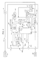
- FIG. 4 is a block diagram of an electronic component arrangement within control module 100.
- the electronic components described hereafter may be arranged as part of a control circuit 400 on the PCB 140 within the control module 100.
- the control circuit 400 of the module 100 includes memory 434, 436 for storing one or more soft-coded function coefficients used during execution of various control functions or algorithms. Since a given soft-coded function coefficient may be specific to a particular tool application, the control module 100 may be suitable for controlling the operation of a plurality of motors and/or for a plurality of different motor applications (e.g. different power tools).
- the soft-coded coefficients can be understood to include coefficient inputs into a given function or algorithm to be performed by the control module 100, and can include function coefficients that may be changed or varied for a given tool or tool application.
- the soft-coded coefficients also include coefficient outputs related to a control and/or protective action to be taken by the control module 100 as a result of implementing the given function or algorithm in the control module 100. Coefficient inputs to, and coefficient outputs from a given function may be changed or linked as desired for a given application.
- Control module 100 is connectable to an AC power source (AC Mains 407) and to the motor armature 20 and tool motor field 30.
- the tool motor armature 20 and the tool motor field 30 may comprise an AC motor 15.
- the control module 100 includes the control circuit 400 therein.
- the control circuit 400 determines a position of a motor control switch 402 and controls the control module 100 if power is provided to the motor armature 20 and motor field 30 based on the position of the motor control switch 402 when the AC power source is applied.
- the control circuit 400 includes a power supply 405 that supplies power to a microcontroller 430 programmed to control certain operations and/or to direct certain functions or protective actions within module 100.
- the power supply 405 may supply a VCC of 5V for example.
- a supply voltage monitor 415 monitors the VCC and provides a sensed input to microcontroller 430.
- the microcontroller 430 can control the triac 420 by providing a gate firing signal via line 418 to the triac 420.
- this type of electronic valve may be embodied as any of a field effect transistor (FET), an insulated gate bipolar transistor (IGBT), a silicone-controlled rectifier (SCR), a voltage control device, etc.
- FET field effect transistor
- IGBT insulated gate bipolar transistor
- SCR silicone-controlled rectifier
- the control module 100 controls the operation of the motor 15 by switching the AC supply voltage 407 to the motor at periodic intervals in relation to the zero crossing of the AC current or voltage waveform, via the microcontroller 430 and gate firing signals applied to the gate of the electronic valve 420 via line 418. These periodic intervals are caused to occur in synchronism with the AC waveform (i.e., the AC supply signal input from AC mains 407) and are measured in terms of a conduction angle, expressed as a number of degrees.
- the conduction angle determines the point within the AC waveform, for both positive and negative half-cycles, at which the electronic valve 420 is fired, thereby delivering electrical energy to the motor 15.
- a conduction angle of 180° per half cycle corresponds to a condition of full conduction, in which triac 420 is fired such that the entire, uninterrupted alternating current from AC mains 407 is applied to the motor 15, i.e., the triac 420 is fired such that current flows through the triac 420 for each positive and negative half cycle of the AC input signal.
- a 90° conduction angle corresponds to developing the AC supply voltage across the motor 15 commencing in the middle of a given half cycle, and thus the triac 420 is fired so that approximately half of the available energy is delivered to the motor.
- Conduction angles below 90° correspond to firing of the triac 420 later in a given half cycle so that even lesser quantities of energy are delivered to the motor 15.
- the triac 420 may be a single-isolated triac, where isolation is internal to the part. More specifically, operation of the motor armature 20 and motor field 30 which constitute the motor 15 is controlled by the control circuit 400 within control module 100. To control operation of the motor armature 20 and motor field 30, the microcontroller 430 controls the current flowing through or voltage applied to motor armature 20 and motor field 30, or both, via electronic cycling of the triac 420.
- control circuit 400 can determine when to open or close the triac 420 based on soft-coded coefficients that can be stored in look-up tables, or from control equations or control methodologies based upon measured factors or parameters such as voltage, speed, current, torque, other external digital inputs (456a, 458a etc.) or any combination of the above.
- a triac 420 is one type of controlled switching device which cannot be 'opened' or turned off by the control circuit 400. However, other devices such as FET's, IGBT's etc, can be turned off. The turn-off of the triac 420 is decided by the AC and motor 15, which causes the current to reduce to zero to thereby allow the triac 420 to turn-off at each AC half-cycle. This does not reduce the control capability of the triac 420 relative to the methodologies referred to herein.
- the control module 100 controls the operation of the motor 15 when the motor control switch 402 is placed in a closed (i.e., 'on') position, thereby allowing current to flow through.
- a function of the control circuit 400 is to monitor the position of the motor control switch 402 and prevent starting of the motor 15 if power is applied to motor 15 with the motor control switch 402 in a shut (i.e. 'On') position.
- Microcontroller 430 may include one or more memory elements.
- Microcontroller 430 may include program ROM 436 (alterable ROM) such as flash memory, a CPU core such as a microprocessor 432, on-board peripherals, and volatile memory such as RAM 434 or SRAM on a single chip construction, for example. Examples of volatile memory include RAM (DRAM, SRAM, SDRAM, VRAM, etc.
- Non-volatile memory such as Electrically Erasable Programmable Read-Only Memory (EEPROM) and Flash memory allows the entire ROM (or selected banks of the ROM) to be electrically erased (flashed back to zero) then written to.
- EEPROM Electrically Erasable Programmable Read-Only Memory
- Flash memory allows the entire ROM (or selected banks of the ROM) to be electrically erased (flashed back to zero) then written to.
- the microcontroller 430 may be one of the ATMEL AVR ® 8-bit RISC microcontrollers, such as the ATmega8 flash microcontroller with 8-Kbyte self-programming Flash Program Memory (EEPROM).
- EEPROM Flash Program Memory
- ROM 436 may be referring to as non-volatile memory such as flash memory EEPROM or simply EEPROM 436.
- module 100's intelligent control is not limited to the example microcontroller 430.
- the intelligent control device could be embodied in hardware and/or software as another microprocessor, an analog circuit, a digital signal processor or by one or more digital ICs such as application specific integrated circuits (ASICs), for example.
- ASICs application specific integrated circuits
- the control circuit 400 with the tool motor 15 (motor armature 20 and motor field 30) is connected in series with motor control switch 402, triac 420 and a shunt resistor 440 between hot and neutral (common) sides of the power source.
- one side of tool motor 15 is connected to the power source, such as to the hot side of AC mains 407 via the power cord 21 ( FIG. 1 ) through the motor control switch 402.
- the other side of the tool motor 15 is connected through triac 420, shunt resistor 440 and power cord 21 to the neutral side 408 of the AC mains 407.
- Shunt resistor 440 may be embodied as an analog current sensor which senses current through the triac 420 and motor 15 and provides a representative low-voltage signal that is amplified at amplifier 445.
- Amplifier 445 has a first input coupled to one side of shunt resistor 440 and a second input coupled to the other side of shunt resistor 440.
- amplifier 445 may be biased (i.e., a bias voltage may be applied at the input so as to shift the amplifier output).
- An output of amplifier 445 may be coupled to a given port of microcontroller 430.
- Shunt 440 is merely one example of a current sensor, alternative current sensors include current transformers, digital sensors, hall-effect sensors, etc., for example.
- the microcontroller 430 may include an analog to digital converter (ADC) 433.
- ADC 433 may be embedded as part of the circuitry of microprocessor 432 and converts analog signals received from various sensors or sources to digital representations for processing by microprocessor 432.
- example analog inputs include inputs from amplifier 445, monitors 415 and 425, power supply 405 and temperature sensor 410. These inputs may be converted to digital representations in the ADC 433 as is known for processing by the microprocessor 432.
- the output from the RC filter formed by 451/452 is a digital input to the microcontroller 430, as is the input from voltage monitor 427.
- Lines 456 and 458 represent digital outputs from the microcontroller 430, and lines 456a and 458a can be digital inputs, analog inputs or even digital outputs.
- the microcontroller 430 outputs a digital gate firing signal (control signal) via line 418 to control firing of the triac 420.
- the control circuit 400 further includes a voltage shaping circuit 450 clamped by diodes 455 and 457 and including an RC filter represented by resistor 451 and capacitor 452.
- the resulting signal input 460 that is output of the voltage shaping circuit 450 is utilized by microcontroller 430 to sense a point in time where the theoretical, ideal sinusoidal AC voltage signal (the AC supply from AC mains 407) crosses the zero-axis and switches from either a positive-to-negative or negative-to-positive voltage. This point is used for timing and synchronization purposes inside the microcontroller 430 of control module100.
- the clamping diodes 455 and 457 protect microcontroller 430 from damage if a voltage spike occurs in the AC source voltage.
- all or part of the voltage shaping circuit 450 may be included in the control circuit 400 or within microcontroller 430.
- the clamping diodes 455 and 457 are internal to the microcontroller 430.
- Control circuit 400 may include one or more temperature sensors 410 designed to sense a temperature and to input a sensed signal via a port to microcontroller 430. Only one sensor 410 is shown for clarity. Temperature sensor 410 may be embodied as an NTC or PTC thermistor, temperature sensing IC or thermocouple, for example. The temperature sensor 410 may communicate the temperature of the control module 100, or the temperature of specific components such as the triac 420 or microcontroller 430. As the function of such temperature sensors 410 are known, a detailed explanation of its functional operation is omitted for purposes of brevity. Multiple temperature sensors 410 could be placed at designated locations within module 100 as required.
- control circuit 400 includes two voltage monitors for monitoring voltage of the triac 420, a gate voltage monitoring circuit (monitor 425) for monitoring a gate voltage of the triac 420 to determine if the triac 420 is conducting during a negative AC half-cycle of the AC waveform applied to triac 420, and a positive VAC half cycle monitoring circuit (monitor 427) which is used to monitor triac voltage to determine if the triac 420 is conducting during the positive AC half cycle.
- a gate voltage monitoring circuit monitoring circuit for monitoring a gate voltage of the triac 420 to determine if the triac 420 is conducting during a negative AC half-cycle of the AC waveform applied to triac 420
- a positive VAC half cycle monitoring circuit monitoring circuit which is used to monitor triac voltage to determine if the triac 420 is conducting during the positive AC half cycle.
- the triac gate voltage monitor 425 includes circuitry for monitoring both the positive and negative AC half cycles, yet software in the microcontroller 430 doesn't utilize the gate voltage monitor 425 in the positive half cycle due to measurement functions performed in the ADC 433. Accordingly, both monitors 425, 427 are used as the microcontroller 430 cannot use the gate voltage monitor 425 during the triac 420/motor current measurement, which is fully utilizing ADC 433 during the positive half cycle. During the negative half wave of the AC cycle, no voltage would be detected by monitor 427, which inputs a digital signal to microcontroller 430. Additionally, both monitors 425, 427 are used for detecting whether triac 420 is conducting following firing, as will be described in further detail below.
- control circuit 400 of FIG. 4 is designed to enable module 100 to provide control for the tool motor 15. Accordingly, as the general structure and electronic circuitry of the control module 100 has been described, example control methodologies are discussed in more detail below.
- re-firing of the triac 420 is required to ensure that the triac 420 is turned back on if the current to a tool motor momentarily goes to zero (either due to a fault event in the electrical supply system (such as a voltage disturbance on the AC supply from AC Mains 407) or due to the motor commutator interrupting current for a brief interval) during a particular AC half-cycle.
- a fault event in the electrical supply system such as a voltage disturbance on the AC supply from AC Mains 407
- the motor commutator interrupting current for a brief interval can happen frequently, if the motor (such as motor 15) is a typical universal motor having a commutator where the motor current can quickly decay to zero during the commutation process, or if the brushes bounce away from the commutator.
- a conventional analog AC motor control system for determining whether the triac 420 has turned off after being fired only monitors the triac gate voltage to determine whether the triac is 'on' or 'off' (i.e. 'on' when the voltage is positive and above some threshold, or negative and below a threshold).
- the triac gate voltage for the entire AC cycle. For example, during the positive AC half-cycle, the triac AC current needs to be measured, and as a result, the gate voltage for determining whether the triac has re-fired cannot be measured by the same analog-to-digital converter (ADC), such as ADC 433.
- ADC analog-to-digital converter
- the triac gate voltage can be monitored by the same ADC, as the current is negative and does not need to be measured (i.e. it is assumed to be the same as the positive half-cycle). Therefore, it is possible to perform triac conduction detection only in the negative AC half-cycle.
- a triac conduction detection algorithm may be implemented by the microprocessor 432 of microcontroller 430 in which triac conduction detection may be performed in both half-cycles of the AC waveform.
- the methodology checks each AC half cycle for whether or not the triac 420 is conducting after it has been fired in accordance with a given control algorithm.
- the algorithm compares actual samplings of triac voltage/gate voltage taken by the two voltage monitoring circuits 425 and 427 against expected states to make a triac 420 on/off determination in each half cycle of the AC supply signal.
- Triac gate voltage monitor 425 monitors the negative AC half cycle and positive VAC 1 ⁇ 2 cycle voltage monitor 427 monitors the positive AC half cycle of the triac voltage.
- control module 100 attempts to re-fire the triac 420.
- This check may be repeated several times at given intervals up to some minimum conduction point (i.e., such as until a 30 degree conduction angle is exceeded -- in both the positive and negative half cycles of the AC waveform. This point represents the last 30 degrees in the 180 degree half-sine wave cycle.
- the triac 420 is not conducting upon reaching the minimum conduction point, the triac 420 is not fired or re-fired for the remainder of the half-cycle. By checking up to the minimum conduction point whether the triac 420 fired or not, the triac 420 has either failed due to some fault condition or the switch 402 is open if it has not yet fired.
- the switch 402 is considered to be open. This enables the ability to detect an open switch 402 without the need of a current measurement circuit.
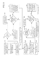
- FIG. 5 is a flow diagram for illustrating a method of detecting whether the triac 420 needs to be re-fired in the control module 100 following an initial firing of the triac 420 from a given control methodology.
- a typical control methodology implemented in the control module 100 requires a given conduction angle which sets the firing angle for both the positive and negative half cycles of the AC waveform to be identical and balanced.
- certain methodologies may cause the positive and negative firing angles to differ from each other and to vary from each other, but which still give an average equal firing in both polarities.
- a first half cycle which in this example is upon detection of a negative-to positive zero cross transition of the AC waveform (510) and hence in the positive AC half cycle, and after a delay has elapsed (515) to wait for the known, given control algorithm in the microcontroller 430 to fire the triac 420 in the half cycle, the voltage across the triac 420 is checked (520) for re-firing using the positive VAC 1 ⁇ 2 cycle voltage monitor 427.
- monitor 427 detects a voltage across the triac 420 (output of 530 is 'YES'), this generates a logic high signal in microcontroller 430 which represents that triac 420 is OFF, and microcontroller 430 will attempt to re-fire the triac 420 (at 540) by sending a gate firing signal over line 418 to maintain conduction. If the output of 530 is 'NO', this indicates that the triac 420 is ON and conducting (at 545), generating a logic low in microcontroller 430.
- monitor 427 repeats sampling voltage across the triac 420 at fixed regular intervals if the minimum conduction point has not been reached (output of 550 is 'NO'). In an example, monitor 427 can repeat sampling voltage across the triac every 9 degrees after the triac 420 has fired up until the minimum conduction point is passed.
- the triac 420 remains in its current ON or OFF state (555) until the next zero-cross transition is detected by microprocessor 432. Similarly, if the triac 420 is still OFF after the minimum conduction point has been reached an/or exceeded, it remains off in the remaining half-cycle until the next zero-cross transition to the opposite half cycle has been detected.
- the above implementation may provide a simple logic input to the digital system (microcontroller 430) that can easily and quickly determine the 'on'/'off' condition of the triac 420 during the positive AC half-cycle without consuming the ADC 433 resource which can be used to measure triac 420 current.
- the triac gate voltage will be negative if the triac 420 is ON and as a result for the ADC 433 in the microcontroller 430, the analog voltage is level shifted such that 0V (at the gate) becomes about 1.8V. This is so the ADC 433 can measure the negative gate voltages. Therefore, triac 420 ON gives a lower analog voltage than a threshold, and triac OFF corresponds to a higher analog voltage than the threshold, which in an example could be about 1.0V.
- triac 420 conduction detection is evaluated in the negative AC half cycle.
- the triac gate voltage is sampled by gate voltage monitor 425 (at 565) and compared to some threshold at 570 (such as a nominal analog voltage value) to determine whether the triac 420 is ON or OFF.
- the triac 420 is OFF and will be re-fired by the microcontroller 430 (at 575) if the measured voltage is higher than this threshold (e.g., nominal analog voltage value, output of 570 is 'YES')), else it is determined to be ON and conducting (at 580), since a triac 420 ON in the negative half cycle gives a lower analog voltage than the threshold value.
- this threshold e.g., nominal analog voltage value, output of 570 is 'YES'
- the microcontroller 430 will continue to attempt to ensure, by checking at regular intervals, that the triac 420 is maintained in the on-state (output of 585 is 'NO') from the moment it is fired until the minimum conduction point is reached (output of 585 is 'YES'), after which the firing of the triac 420 is no longer critical for the reminder of the half-cycle.
- the triac 420 remains in its current state (at 590) and the process at 510 repeats upon the following zero-cross detection.
- triac 420 'on'/'off' determination can be done in both half cycles of the triac voltage using a gate voltage monitor 425 and/or a positive VAC 1 ⁇ 2 cycle voltage monitor 427.
- the triac 420 is either re-fired as necessary for the remainder of the AC half-cycle in an attempt to re-establish conduction of the triac 420, or is maintained ON for the duration of the half-cycle via subsequent checks.
- Re-firing is typically limited to a given number of attempts and ceases once the minimum conduction point in any given 180 degree half-cycle is reached (a point where very little voltage is applied to the motor 15 to cause any noticeable torque or rotation, such as a 30 degree conduction angle, for example).
- Another function of the algorithm is to ensure that the triac 420 is re-fired once conduction from the previous AC half-cycle has ceased. This extended conduction interval is typical for motor loads where the current can significantly lag the voltage, and as a result the current from an example negative AC half-cycle will continue into the positive AC half-cycle before the triac 420 actually commutates 'off'.
- triac 420 firing should not commence until the triac 420 has turned OFF from the previous AC half-cycle.
- This turning off point can be determined either by monitoring triac current, triac gate voltage from monitor 425 and/or triac voltage from monitor 427 to establish when the triac 420 has actually turned 'off'.
- control circuit 400 of control module 100 may be configured to implement a zero cross detection methodology to establish reliable phase angle control for triac 420 (also referred to as firing angle control or conduction angle control) for the triac 420.
- Zero cross detection enables synchronization between the AC supply (which is an input AC voltage signal from AC mains 407 to the tool 10 and control module 100) and the control module 100, so as to provide a desired level of noise immunity for situations where the normal AC supply is disturbed by one or both of the AC tool control itself and external influences on the AC supply signal input from AC mains 407.
- accurate zero-cross detection enables more precise timing for desired firing angle control for triac 420, while providing a noise immune way to establish zero crossing points on AC supply waveforms which have noise (e.g., standalone AC generators).
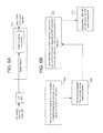
- FIG. 6A is a block diagram to illustrate a zero-cross detection circuit portion of the control circuit 400 for implementing zero cross detection
- FIG. 6B is a flow chart describing a method of detecting zero crossings of the AC supply to tool 10.
- a low-pass filter 450 (see FIG. 4 ) optionally can be combined with a digital blanking circuit 620 within controller 430 to implement zero cross detection.
- the digital blanking circuit 620 may be a software-based algorithm stored in EEPROM 436 and implemented by microprocessor 432.
- the digital blanking circuit 620 can detect zero crosses without a filtered input of the AC supply via RC filter 450.
- the AC supply is digitized in controller 430 by a normal digital input (not shown) to generate a digital signal.
- a digital signal is then processed in a software-based digital blanking circuit 620 within microcontroller 430. Functionality of the digital blanking circuit 620 is invoked under control of the microprocessor 432 to eliminate unwanted noisy zero crosses, as to be described in more detail below with regard to FIG. 6B .
- the low pass-filter 450 is merely one example of a filter usable to filter the AC supply signal.
- a band-pass filter (BPF) or phase-locked loop (PLL) may be used to filter a part of the AC supply signal from AC mains 407.
- the LPF may filter the analog AC voltage signal to remove frequencies in excess of 80 Hz which typically represents the frequency of the noise that occurs around the zero-cross of the AC supply signal.
- FIGS. 6A and 6B which shows an example where optional filtering is employed
- a part of the AC supply signal from AC mains 407 is filtered by LPF 450 to generate a filtered analog output signal.
- the analog output signal is digitized in controller 430 by a digital input of the controller 430 to generate a digital signal.
- This digital signal is then input into the software-based digital blanking circuit 620, the functions of which are iterated by the microprocessor 432 to eliminate unwanted noisy zero crosses.
- the digital blanking circuit 620 is a software-based algorithm stored in memory accessible by the microprocessor 432 from EEPROM 436.
- the digital blanking functionality under control of microprocessor 432, accepts the first zero cross transition, as represented in the digital signal, as a validly detected zero cross signal for a given (or current) AC half cycle (650), and then ignores or rejects remaining zero crosses (655) in the digital signal for a specified blanking period.
- this blanking period can be variable based on the frequency of the AC supply. All zero crosses are rejected until this blanking period has elapsed.
- the zero cross occurring at the next opposite polarity transition after the blanking period elapses is then accepted (660) as the next valid zero cross in that half cycle of the AC supply voltage waveform.
- This process is repeated (670) for each given AC half-cycle such that only the first AC zero cross is used for each AC half-cycle.
- This blanking period (i.e., 10 milliseconds for the 50Hz example above) may be reduced to allow the control module 100 to operate over a range of AC supply voltage frequencies (e.g. 40Hz to 70Hz) and as a result, the half-cycle blanking period may be reduced to about 6-8 msec.
- An example blanking period for a given half cycle of the AC supply may be about 6.125 msec., for example.
- Using digital blanking, with or without filtering, may enable zero-cross detection in a low cost system, while providing a robust zero-cross signal which is immune to AC voltage supplies where noise is very common, such as portable generators.
- the additional use of a low-pass filter may eliminate the majority of the high-frequency noise that occurs around the zero-cross of the AC supply signal.
- Use of a software-based digital blanking unit may eliminate other 'false' zero crosses which may occur throughout the AC supply half-cycles caused by unusual sources such as portable generators.
- the current measurement circuitry includes the shunt 440 to convert the actual measured current to an analog low voltage value representative of the current for measurement purposes.
- Shunt 440 may be a low resistance value (e.g. 5 milliohms) and as a result the representative voltage (e.g. 5 millivolts per ampere) from the shunt 440 may need to be amplified to allow a digital controller such as the microcontroller 430 to resolve and measure the current. This amplification is provided by amplifier 445.
- ADC analog-to-digital converter
- ADC 433 which will resolve the voltage signal input from shunt 440 to about 2.5 millivolts (i.e. 10-bit resolution). Therefore, to maximize the resolution of the ADC 433, a gain of 10 may be introduced using amplifier 445 between the shunt 440 and the ADC 433.
- Amplifier 445 may be an operational amplifier (op-amp) such as a single-supply rail-to-rail amplifier, for example.
- Amplifier 445 like all amplifiers, may be biased, e.g., may have an offset voltage or bias voltage applied at its input.
- resistor components may be used to adjust the actual shunt voltage seen at the amplifier 445 input, so that the output is biased. This offset voltage can be significant as compared to the 0.25V input signal from shunt 440.
- amplifier 445 can be biased in such a way that the op-amp offset, whether positive or negative, still permits a true zero current value to be measured by the ADC 433 from the amplifier 445 output under all offset conditions of the amplifier 445.
- the input of the amplifier 445 may be biased in such a way that with a zero current input, the output of the amplifier 445 is set to be above 0V or 'ground' regardless of the amplifier offset.
- the compensation value or zero-current offset is an ADC value that is measured in a situation where there is no current-the triac 420 is not fired. For example, this is done in a functional test procedure during manufacture of the control module 100.
- the ADC value output of ADC 433 can be measured and recorded in EEPROM 436 as a compensation value representative of the voltage offset in amplifier 445.
- the compensation value i.e., an 'offset ADC value' or zero-current offset
- the microcontroller is subtracted in the microcontroller from an actual current ADC value to obtain the true current measurement for a particular sample (as scaled by the amplifier 445 and shunt 440).
- a true current measurement such as an average current value across triac 420 in a given half cycle
- ADC samples from the shunt 440/op-amp 445 are taken repetitively throughout the positive voltage half-cycle, and summed together in the microcontroller 430.
- the microcontroller 430 subtracts the compensation value (zero-current offset) to obtain the true current measurement for that ADC value.
- the microcontroller 430 senses a negative going zero-cross of the AC waveform, the summed value is averaged (divided by the number of samples), and at this point the result is proportional to the average AC current flowing during the AC half-cycle. In this way, any amplifier offsets from amplifier 445 are removed from the true current ADC measurement, regardless of the actual amplifier 445 offset bias.
- a potential benefit of amplifier biasing is that negative currents can be measured.
- the ADC 433 is often integrated into the microcontroller 430. It uses the same Vcc (typically +5Vdc, but possibly +3.0Vdc or any other voltage) as the microprocessor 432 in the microcontroller 430. Therefore, only voltages between Vss (ground potential or 0.0 Volts) and Vcc can be measured by the ADC 433.
- Vcc the voltage across the shunt 440 is amplified such that the maximum instantaneous current becomes Vcc (and Vcc is the analog reference for the ADC 433). This is accomplished by adjusting the amplification factor of the amplifier 445.
- a voltage of Vcc is converted by the ADC 433 into the full-scale digital value. For a 10-bit ADC, full-scale is a numerical value of 1023 counts, and the 0.0 Volt conversion value is a numerical value of zero counts.
- a peak current of 64 Amperes denotes a full-scale ADC output and zero amperes denotes a zero ADC output, or zero counts.
- an instantaneous current of 32 Amperes becomes 1023 counts
- an instantaneous current of -32 Amperes becomes zero counts.
- a value of 64 Amperes is now off scale and will be clipped to a numerical value of 1023, in this second example.
- the electrical bias applied to the amplifier need not be so large as to make the zero current equal Vcc/2.
- the positive half-cycle current may be measured for the positive AC voltage half-cycle. Since the AC current typically lags the voltage by a small amount, some of the current flowing during the positive AC voltage half-cycle is negative.
- the amplifier 445 biasing as described above therefore allows these small negative currents to be measured at the start of the positive voltage AC half-cycle. If the negative currents are inverted and considered positive in the microcontroller 430, the complete AC half-cycle of current can actually be measured. This is discussed in more detail hereafter.
- Proper current calibration is also necessary for accurate firing angle control of triac 420.
- Current calibration is necessary from a practical standpoint to allow for shunts, amplifiers, analog references, and ADCs which have a wide range of operational characteristics.
- the accuracy of current measurement may be dictated by the accuracy of the shunt 440, the amplifier gain and amplifier bias or offset at op-amp 445, the ADC 433 accuracy and a voltage reference for the ADC 433 (not shown).
- Current calibration may be performed during a testing phase (such as during control module 100 manufacture) to determine an ADC compensation value used to scale all current measurements.
- the triac 420 conducts a known and accurate current that is sensed by shunt 440, amplified at op-amp 445 and input into ADC 433 to determine an ADC compensation value.
- This ADC compensation value is used to compute a Current Calibration Factor (CCF) during the testing phase.
- CCF Current Calibration Factor
- the CCF is equal to 128 times the expected value divided by the difference of the measured value less the zero-current value.
- an expected value of 320, and a measured value of 320 the CCF is 128.
- This CCF is recorded in microcontroller 430 non-volatile memory and used in real-time calculations by the microcontroller 430 to compute the actual current value from the measured current value.
- this CCF value is stored in EEPROM 436 and used by the operational software within the microcontroller 430 of the control module 100 to scale all current measurements, such that all inaccuracies of the control module 100 are calibrated out.
- the CCF can be computed in such a way that values of Shunt 440 resistance, Amplifier 445 gain, and ADC reference voltage 433 give a perfect Current Calibration Factor value of 128. If the resistance of the shunt 440 is lower than nominal, then the CCF will be greater than 128. If the resistance of the shunt 440 is higher than nominal, then the CCF will be lower than 128. Similarly, if the Amplifier gain of amplifier 145 is lower than nominal, then the CCF will be greater than 128, and less than 128 if higher than nominal.
- the measured current value is multiplied by the CCF and divided by 128.
- a CCF of 128 becomes multiplication by a factor of 1. If the shunt resistance is one-half of nominal, then the CCF would be 256. Suppose further that during normal operation the instantaneous current flowing through the triac 420 is precisely that current that should give a value of 128. Then, multiplying this measured current value of 64 by 256, the CCF, and dividing it by 128 would restore the measurement of 64 to a value of 128, the proper value. It is understood that before applying the CCF, any current offset must be removed from the current measurement.
- control module 100 may utilize hysteresis for motor speed measurement and control.
- speed is determined using a magnet on the motor and a pick-up coil (inductor) placed nearby.
- the pick-up coil assembly 250 is configured to detect motor speed of tool motor 15.
- the tool motor 15 which is comprised of a tool motor armature 20 rotating within a tool motor field 30
- the pick-up coil assembly 250 is configured to detect motor speed of tool motor 15.
- FIG. 7 illustrates an example circuit used in motor control module 100 to determine motor speed.
- FIG. 7 is provided to illustrate a way to measure the motor speed using a pickup inductor and a comparator so as to output a set of pulses within the microcontroller 430.
- the frequency of the pulses is directly proportional to the speed of the motor 15.
- the microcontroller 430 can perform a control algorithm to control the measured speed to a desired value as determined by various control inputs.
- Microcontrollers such as microcontroller 430 in FIG. 4 may contain one or more comparators which can trigger a response if the comparator output goes above or below a reference voltage.
- circuit 700 includes a comparator 710, a voltage divider circuit 720, an RC filter 730 and a hysteresis resistor (shown as R3).
- the voltage divider circuit 720 (resistors R1 and R2) creates a fixed voltage reference (Vref) as one input 715 to the comparator 710.
- the second input (tachometric input 725) is the voltage signal (Vcoil) from the pick-up coil assembly 250.
- the second input 725 is filtered by the RC filter 730 to reduce the amount of noise going into the comparator 710.
- the microprocessor 432 in controller 430 sees a low output at the comparator 710. As the motor voltage (Vcoil) drops below Vref, the microprocessor 432 sees a high output on the comparator 710.
- the controller 430 measures the time period between these high-to-low-to-high transitions, motor speed can be determined. Without hysteresis, the reference voltage Vref is fixed and will not change. If the measured voltage signal Vcoil is hovering around the Vref and noise is induced in the system, the microprocessor 432 would see multiple high/low transitions resulting in inaccurate speed measurements by the controller 430.
- circuit 700 includes a third hysteresis resistor (R3) controlled via software through a port pin 740 on the microcontroller 430. If the port pin 740 is configured as an output and connected to ground, the resistor R3 affects the voltage divider created by R1 and R2 by reducing Vref.
- R3 third hysteresis resistor
- the port pin 740 is re-configured as an output and connected to Vcc.
- Vref the value of Vref is determined by the values of R1, R2, R3.
- Vcoil must increase to a higher value before the comparator 710 will switch output again.
- the controller 430 employs comparator hysteresis, using the hysteresis resistor R3, in providing speed measurements from the pick-up coil in close proximity to a rotating magnet of the tool motor 15.
- the changing/switching of the voltage reference level Vref using hysteresis makes it less likely for any noise on the second tachometric input 725 of the comparator 710 to exceed the switched reference level (as the switching of the port pin 740 moves the reference away from the switching point of the comparator 710) and minimizes false comparator 710 output events.
- This combination may provide software level control of the comparator 710 output, potentially providing more reliable speed measurements as noise on the tachometric input (second input 725) is compensated for using the hysteresis resistor R3 to adjust Vref.
- the control module 100 estimates average current flowing through the triac 420 using an estimation algorithm in an effort to control the conduction angle of triac 420 in response to changing load of the tool motor. Accurate estimation of the current flowing through the triac 420 is conducive to accurate control. There are multiple ways to characterize time-varying current that has a mean value of zero amperes, such as through calculations of Root-Mean-Square (RMS) current and average current.
- RMS Root-Mean-Square
- Average current could also be computed for negative excursions, i.e., in the negative AC half-cycle, but this value must be the same as average current during positive excursions over the fundamental frequency period of time. Accordingly, in an example below current flowing during the positive half-cycle will be used to estimate average current.
- the control module 100 detects zero crossings by monitoring the AC supply voltage that powers the power tool 10 and the module 100.
- the zero-crossings may be used to establish the AC power frequency so that the microcontroller 430 may apply corrections to its outputs to compensate for deviations from the nominal frequency.
- the positive-going zero crossing of AC supply voltage marks the beginning of the positive half-cycle
- the negative-going zero crossing of AC supply voltage marks the end of the positive half-cycle.
- FIG. 8 illustrates an example positive half cycle of an AC voltage waveform.
- the period of time between the positive-going zero-crossing (at 810) and the negative-going zero-crossing (at 820) defines the positive AC half-cycle.
- the current through the shunt 440 is measured and accumulated; these are show as samples 830.
- this accumulation is divided by the number of samples, providing the average current flowing through the triac 420 during the positive half-cycle of the AC voltage waveform.
- biasing of the op-amp 445 to shift the ADC counts allows negative current to be measured by the ADC 433, down to the limit of the biasing.
- Applying a bias voltage to the op-amp 445 effectively shifts the range of current values that may be measured, such that a handful of negative current values may be measured in the vicinity of the negative-to-positive transition of the positive AC half cycle.
- the AC current will not be completely in-phase with the AC voltage, but will be slightly out-of-phase.
- the phase angle between voltage and current will be neither zero degrees (purely resistive) nor 90 degrees (purely inductive), but somewhere in between.
- the current will have both an in-phase component, and an out-of-phase component, with respect to the voltage.
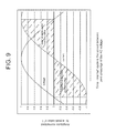
- FIG. 9 illustrates an AC voltage and current waveform for a purely inductive load.
- a conventional current averaging estimation algorithm takes the sum of all individual current measurements and then divides by the number of measurements (number of samples) at the end of the positive half-cycle (when the voltage waveform crosses zero in the negative-going direction). If certain measured individual current samples are negative, these negative values effectively subtract from the summation of current over the positive voltage half-cycle; this skews the calculation for estimated average current downward from its true value, because the average current value is assumed only for the positive AC half-cycle of current.
- the average current over the positive voltage half-cycle would be exactly zero.
- the negative area under the current curve from 0 to 90 degrees, exactly equals the positive area under the current curve, from 90 to 180 degrees.
- the average current is precisely zero over this interval.
- the true current is clearly not zero, but rather some non-zero value.
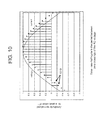
- FIG. 10 illustrates voltage and current waveforms in the positive AC half cycle for a slightly inductive load to describe a method of estimating average current in accordance with an example embodiment.
- an improved algorithm to estimate true average current may disregard the individual negative current measurements; these samples would not be added or accumulated to the sum of current measurements in the positive half-cycle. The total sum of current measurements would thus equal the summation of non-negative current measurements between the two zero-cross transitions. As shown in FIG. 10 , the two measurements indicated at 1010 would be ignored.
- ADC values determined by ADC 433 from the non-negative samples measured by shunt 440 would be accumulated, then divided by the total number of all measurements in the half-cycle between the two zero cross transition points in order to determine the estimated Average current.
- the resulting estimated Average current value would be closer to the true average current.
- Another estimate of the Average current would accumulate ADC values determined by ADC 433 from the non-negative samples measured by shunt 440 and then divide by the total number of non-negative measurements in the half-cycle between the two zero cross transition points. Accordingly, in the example of FIG. 10 , ignoring negative current measurements may improve the estimation of Average current flowing through the triac 420.
- FIG. 11 illustrates voltage and current waveforms in the positive AC half cycle for a pure inductive load to describe a method of estimating average current in accordance with another example embodiment.
- the summation of current measurements will produce a more robust estimation of the average current. This is because subtracting negative measurements is equivalent to taking the absolute value of all current measurements before summation.
- the average current over the positive voltage half-cycle is equal to the average current over the positive current half-cycle.
- the estimation of average current flowing through the triac 420 may be even more robust if the current waveform is symmetrical about the 90 degree phase point, as shown in FIG. 11 .
- the op-amp 445 for the shunt 440 measurements so that zero current (as determined by microcontroller 430 reading the ADC values) is the mid-point of the measuring range, accurate current measurements may be made over the entire 360 degrees of the AC cycle.
- the op amp 445 may be biased at its input so that its output to ADC 433 allows a full range of positive and negative current measurements to be measured by microcontroller 430 at the output of ADC 433. This would bias the zero-current shunt signal to the mid-point of an example measuring range, such that a range encompassing a number of negative and positive current measurements could be measured.
- An example range may be between +/-32 Amperes of current. This allows current to be computed over a complete AC cycle.
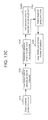
- FIG. 12A is a flowchart for illustrating a method for estimating average current through the triac of the motor control module in accordance with an example embodiment
- FIG. 12C is a flowchart for illustrating a method for estimating average current through the triac 420 in accordance with another example embodiment.
- FIGS. 12A and 12B correspond to the graph of FIG. 10
- FIG. 12C corresponds to the graph of FIG. 11 .
- the microcontroller 430 senses a positive-going zero-crossing of the AC voltage waveform (1210), which is a trigger for the microcontroller 430 to begin sampling the current via the shunt 440/op-amp 445 at regular intervals (1220). For each ADC value representing a given current sample that is received from the ADC 433, the microcontroller 430 will determine an adjusted value (1230). This is done by subtracting a zero-current offset from the ADC value to get the adjusted current sample value. This zero-current offset has also been referred to as a compensation value above, and has been previously determined in testing/calibration during control module 100 manufacture. The zero-current offset is stored in non-volatile memory such as ROM or EEPROM 436.
- the microcontroller 430 next adds only those adjusted values that are positive (1240) to determine a sum. Negative current samples are ignored. Once the microcontroller detects the negative-going zero-crossing of AC voltage waveform (1250), the sum is divided (1260) by the number of samples to determine the estimated Average current.
- FIG. 12B is the same as FIG. 12A , with the exception that the estimated Average current is determined by dividing the sum by the number of non-negative samples (1260a), instead of all samples.
- FIG. 12C includes the same steps as FIG. 12A to estimate average current with the exception of step 1240b.
- the microcontroller 430 thus adds the absolute values of all the current samples in the positive AC half cycle (1240) in determining the sum.
- the negative current samples within the positive AC half cycle are therefore included in the Average current calculation, but are additive to the sum as the absolute value is used.
- microprocessors and microcontrollers use an internal oscillator as a fundamental clock for the execution of programmed instructions.
- these internal oscillators are not precise and can be adjusted by means of an oscillator calibration register within the microcontroller.
- Microprocessor manufacturers adjust these oscillator calibration registers at their factory to give a certain frequency of oscillation at nominal operating voltage and nominal room temperature. At other operating voltages, and other temperatures, the fundamental frequency of oscillation may deviate from the norm.
- the oscillator in microcontroller 430 of the control module 100 should be adjusted because the AC line frequency needs to be measured to determine if it is 50Hz or 60 Hz, which are typical operating frequencies, or if the AC line frequency is at another, different frequency used to communicate with the module 100 for the purpose of loading and reading coefficients necessary for the proper operation of the power tool. Accordingly, an example implementation to calibrate the fundamental frequency of oscillation in microcontroller 430 is to count the number of oscillations between successive zero-crossings of the AC line which powers the control module 100. Either current or voltage can be sampled.
- Microcontroller 430 includes counters that can count the fundamental frequency, which may be divided by some prescaler within the microcontroller 430. If the number of counts between successive zero-crossings is lower that expected, then the oscillator calibration register in microcontroller 430 is changed by writing a new value to the register so as to increase the frequency and thus increase the number of counts. If the number of counts between successive zero-crossings is higher that expected, then the oscillator calibration register is changed in such a way (such as by writing a new value to the register) as to decrease the frequency and thus decrease the number of counts between successive zero-crossings.
- the oscillator calibration register in the microcontroller 430 can be calibrated so that the fundamental frequency of oscillation enables precise measurement of the AC line frequency. For example, an initial oscillator calibration register value is set, and the number of frequency oscillations between successive zero crossings of the AC waveform is counted by software in microcontroller 430 to determine a count. This count can be compared against a nominal count value stored in memory of the microcontroller 430 (i.e., some threshold). If the count is less than the nominal count value, the oscillator calibration register is calibrated by the microcontroller 430 increasing the fundamental frequency of oscillation in the oscillation register. If the count is greater than or equal to the nominal count value, the microcontroller 430 decreases the fundamental frequency of oscillation in the oscillation register.
Landscapes
- Engineering & Computer Science (AREA)
- Power Engineering (AREA)
- Microelectronics & Electronic Packaging (AREA)
- Control Of Ac Motors In General (AREA)
- Control Of Electric Motors In General (AREA)
- Protection Of Generators And Motors (AREA)
- Control Of Direct Current Motors (AREA)
- Ignition Installations For Internal Combustion Engines (AREA)
Applications Claiming Priority (4)
| Application Number | Priority Date | Filing Date | Title |
|---|---|---|---|
| US72601105P | 2005-10-12 | 2005-10-12 | |
| US81708506P | 2006-06-29 | 2006-06-29 | |
| EP06122174A EP1775831B1 (de) | 2005-10-12 | 2006-10-12 | Motorsteuerungsschaltung für ein Elektrowerkzeug |
| EP07114561A EP1858154B1 (de) | 2005-10-12 | 2006-10-12 | Verfahren zur Schätzung des durchschnittlichen Stroms eines Triacs in einem Motorregelmodul |
Related Parent Applications (1)
| Application Number | Title | Priority Date | Filing Date |
|---|---|---|---|
| EP07114561A Division EP1858154B1 (de) | 2005-10-12 | 2006-10-12 | Verfahren zur Schätzung des durchschnittlichen Stroms eines Triacs in einem Motorregelmodul |
Publications (2)
| Publication Number | Publication Date |
|---|---|
| EP1990909A2 true EP1990909A2 (de) | 2008-11-12 |
| EP1990909A3 EP1990909A3 (de) | 2009-02-18 |
Family
ID=37663384
Family Applications (4)
| Application Number | Title | Priority Date | Filing Date |
|---|---|---|---|
| EP06122174A Not-in-force EP1775831B1 (de) | 2005-10-12 | 2006-10-12 | Motorsteuerungsschaltung für ein Elektrowerkzeug |
| EP08163332A Withdrawn EP1990909A3 (de) | 2005-10-12 | 2006-10-12 | Regelungsverfahren für ein Motorregelmodul |
| EP06825975.3A Withdrawn EP1961109A4 (de) | 2005-10-12 | 2006-10-12 | Regelungs- und schutzverfahren für ein motorregelmodul |
| EP07114561A Not-in-force EP1858154B1 (de) | 2005-10-12 | 2006-10-12 | Verfahren zur Schätzung des durchschnittlichen Stroms eines Triacs in einem Motorregelmodul |
Family Applications Before (1)
| Application Number | Title | Priority Date | Filing Date |
|---|---|---|---|
| EP06122174A Not-in-force EP1775831B1 (de) | 2005-10-12 | 2006-10-12 | Motorsteuerungsschaltung für ein Elektrowerkzeug |
Family Applications After (2)
| Application Number | Title | Priority Date | Filing Date |
|---|---|---|---|
| EP06825975.3A Withdrawn EP1961109A4 (de) | 2005-10-12 | 2006-10-12 | Regelungs- und schutzverfahren für ein motorregelmodul |
| EP07114561A Not-in-force EP1858154B1 (de) | 2005-10-12 | 2006-10-12 | Verfahren zur Schätzung des durchschnittlichen Stroms eines Triacs in einem Motorregelmodul |
Country Status (5)
| Country | Link |
|---|---|
| US (1) | US7446493B2 (de) |
| EP (4) | EP1775831B1 (de) |
| AT (2) | ATE405027T1 (de) |
| DE (2) | DE602006002218D1 (de) |
| WO (1) | WO2007044930A2 (de) |
Families Citing this family (39)
| Publication number | Priority date | Publication date | Assignee | Title |
|---|---|---|---|---|
| DE102007060242A1 (de) * | 2007-12-14 | 2009-06-18 | Robert Bosch Gmbh | Verfahren und Vorrichtung zum Betreiben eines elektrischen Antriebs mithilfe einer Phasenanschnittssteuerung |
| DE102008002119A1 (de) * | 2008-05-30 | 2009-12-03 | Robert Bosch Gmbh | Verfahren zur Drehzahlregelung, elektrischer Antrieb und Elektrowerkzeug |
| CN201421494Y (zh) * | 2009-05-11 | 2010-03-10 | 中山大洋电机股份有限公司 | 一种微处理器时钟检测电路及直流无刷电机的单片机mcu时钟检测电路 |
| US8465263B2 (en) | 2009-06-22 | 2013-06-18 | Wagner Spray Tech Corporation | Dynamic control of an electric drive |
| EP2292383B1 (de) * | 2009-09-04 | 2016-04-06 | Black & Decker Inc. | Redundanter Überdrehzahlschutz für Elektrowerkzeuge |
| US8919669B2 (en) | 2010-04-05 | 2014-12-30 | Wagner Spray Tech Corporation | Fluid intake assembly for remote fluid source |
| US9038923B2 (en) | 2010-04-05 | 2015-05-26 | Wagner Spray Tech Corporation | Fluid level indicator in an airless fluid sprayer |
| US9604236B2 (en) | 2010-04-05 | 2017-03-28 | Jeffrey E. Sandahl | Fluid intake assembly for a fluid sprayer |
| DE102010027981A1 (de) * | 2010-04-20 | 2011-10-20 | Robert Bosch Gmbh | Winkelschleifer |
| EP2439546B1 (de) * | 2010-10-06 | 2015-04-29 | STMicroelectronics (Tours) SAS | Verfahren zur Detektion eines Überstroms in einem Triac |
| GB2485578B (en) * | 2010-11-19 | 2014-10-15 | Black & Decker Inc | Power tool control system |
| TWI456382B (zh) * | 2011-10-03 | 2014-10-11 | Leadtrend Tech Corp | 電源供應器、用於電源供應器的電源管理裝置及用於電源管理裝置之低電壓保護以及過溫度保護之方法 |
| US8878470B2 (en) * | 2011-10-18 | 2014-11-04 | Regal Beloit America, Inc. | Methods and apparatus for reducing size and costs of motor controllers for electric motors |
| BR102013003829A2 (pt) * | 2013-02-19 | 2014-11-04 | Whirlpool Sa | Método de acionamento de motor elétrico de lavadora |
| US9559628B2 (en) | 2013-10-25 | 2017-01-31 | Black & Decker Inc. | Handheld power tool with compact AC switch |
| EP2887525B1 (de) * | 2013-12-19 | 2018-07-11 | Electrolux Appliances Aktiebolag | System zur Überwachung elektrischer Lasten sowie zur Überwachung der Ansteuerungsvorrichtungen dieser elektrischen Lasten |
| CN104614107B (zh) * | 2015-01-12 | 2017-12-12 | 江苏金陵自控技术有限公司 | 一种全电子式电机转矩实时检测电路 |
| CN105818109A (zh) * | 2015-01-22 | 2016-08-03 | 苏州宝时得电动工具有限公司 | 动力装置、电动工具及电动工具系统 |
| JP6348869B2 (ja) * | 2015-04-09 | 2018-06-27 | ミネベアミツミ株式会社 | 計器の駆動制御装置 |
| WO2017136599A1 (en) * | 2016-02-03 | 2017-08-10 | St. Jude Medical, Cardiology Division, Inc. | System and method of cancellation of source induced errors |
| US20170303766A1 (en) * | 2016-04-22 | 2017-10-26 | General Electric Company | Controlling Operation of Dishwasher Motor |
| CN107465368B (zh) * | 2016-05-30 | 2023-09-26 | 德昌电机(深圳)有限公司 | 电机及其驱动电路与驱动方法 |
| CN107520816B (zh) * | 2016-06-21 | 2020-01-14 | 苏州宝时得电动工具有限公司 | 动力工具的保护方法及系统 |
| IT201700027219A1 (it) * | 2017-03-14 | 2018-09-14 | Esseci Srl | Dispositivo di attivazione e resistenza ptc |
| US10833503B2 (en) | 2017-08-11 | 2020-11-10 | Black & Decker Inc. | Hardware control for prevention of dangerous restart in a power tool |
| CN109687780A (zh) * | 2017-08-25 | 2019-04-26 | 德昌电机(深圳)有限公司 | 电机及其驱动电路与驱动方法 |
| CN207917158U (zh) * | 2018-01-30 | 2018-09-28 | 深圳市大疆创新科技有限公司 | 电子调速器及无人机 |
| CN214352217U (zh) | 2018-02-28 | 2021-10-08 | 米沃奇电动工具公司 | 电动工具 |
| EP3759811B1 (de) | 2018-02-28 | 2024-04-24 | Milwaukee Electric Tool Corporation | Simuliertes verlangsamungssystem und verfahren für elektrowerkzeuge |
| US11858106B2 (en) | 2019-08-08 | 2024-01-02 | Black & Decker Inc. | Power tools and power tools platform |
| IT202000016672A1 (it) * | 2020-07-09 | 2022-01-09 | De Longhi Appliances Srl | Metodo e circuito di controllo per un motore a corrente continua |
| EP4009125B1 (de) | 2020-12-02 | 2025-01-29 | Andreas Stihl AG & Co. KG | Verfahren zum bestimmen einer information über einen zustand eines antriebsmotorsystems und/oder eines antriebsakkumulatorpacks eines garten-, forst- und/oder baubearbeitungsgeräts und system zum bestimmen einer information über einen zustand eines antriebsmotorsystems und/oder eines antriebsakkumulatorpacks eines garten-, forst- und/oder baubearbeitungsgeräts |
| US12434371B2 (en) | 2022-03-23 | 2025-10-07 | Milwaukee Electric Tool Corporation | Electronic clutch for power tools |
| US12115642B2 (en) | 2022-05-03 | 2024-10-15 | Milwaukee Electric Tool Corporation | Power tool including loss of control mitigation |
| US12122028B2 (en) | 2022-05-26 | 2024-10-22 | Milwaukee Electric Tool Corporation | Electronic clutch for powered fastener driver |
| US12539590B2 (en) | 2023-01-12 | 2026-02-03 | Milwaukee Electric Tool Corporation | Printed circuit board assembly with multiple conduction paths |
| US12466047B2 (en) | 2023-03-22 | 2025-11-11 | Milwaukee Electric Tool Corporation | Power tools including a plurality of temperature sensors |
| CN118731815B (zh) * | 2024-07-26 | 2025-12-02 | 联合汽车电子有限公司 | 用于提高电流检测精度的补偿方法、装置、电机控制器及介质 |
| CN120433127B (zh) * | 2025-05-27 | 2025-11-21 | 河南嘉晨智能控制股份有限公司 | 一种电机三相电流过流检测保护电路及方法 |
Family Cites Families (9)
| Publication number | Priority date | Publication date | Assignee | Title |
|---|---|---|---|---|
| US5410229A (en) * | 1992-07-31 | 1995-04-25 | Black & Decker Inc. | Motor speed control circuit with electronic clutch |
| JP3348296B2 (ja) | 1992-07-31 | 2002-11-20 | ソニー株式会社 | センサレスモータの駆動装置 |
| JPH07333260A (ja) | 1994-06-02 | 1995-12-22 | Yamaha Motor Co Ltd | 電流センサのオフセット除去回路 |
| US5986417A (en) | 1995-04-26 | 1999-11-16 | Sgs-Thomson Mocroelectronics S.A. | Sensorless universal motor speed controller |
| US6017354A (en) * | 1996-08-15 | 2000-01-25 | Stryker Corporation | Integrated system for powered surgical tools |
| JPH10300798A (ja) | 1997-04-24 | 1998-11-13 | Sanyo Electric Co Ltd | オフセットの自動補正回路を備える電流検出回路 |
| KR100317301B1 (ko) * | 2000-01-21 | 2001-12-22 | 구자홍 | 선형 압축기의 피스톤 위치 제어장치 및 방법 |
| NZ541517A (en) | 2003-02-07 | 2007-03-30 | Black & Decker Inc | Switch sensing to prevent inadvertent motor startup |
| US7102303B2 (en) | 2003-04-30 | 2006-09-05 | Black & Decker Inc. | Generic motor control system and method |
-
2006
- 2006-10-11 US US11/545,734 patent/US7446493B2/en not_active Expired - Fee Related
- 2006-10-12 DE DE602006002218T patent/DE602006002218D1/de active Active
- 2006-10-12 EP EP06122174A patent/EP1775831B1/de not_active Not-in-force
- 2006-10-12 EP EP08163332A patent/EP1990909A3/de not_active Withdrawn
- 2006-10-12 AT AT06122174T patent/ATE405027T1/de not_active IP Right Cessation
- 2006-10-12 EP EP06825975.3A patent/EP1961109A4/de not_active Withdrawn
- 2006-10-12 WO PCT/US2006/040254 patent/WO2007044930A2/en not_active Ceased
- 2006-10-12 EP EP07114561A patent/EP1858154B1/de not_active Not-in-force
- 2006-10-12 DE DE602006020252T patent/DE602006020252D1/de active Active
- 2006-10-12 AT AT07114561T patent/ATE499738T1/de not_active IP Right Cessation
Also Published As
| Publication number | Publication date |
|---|---|
| DE602006002218D1 (de) | 2008-09-25 |
| EP1990909A3 (de) | 2009-02-18 |
| ATE405027T1 (de) | 2008-08-15 |
| DE602006020252D1 (de) | 2011-04-07 |
| WO2007044930A3 (en) | 2007-12-27 |
| EP1961109A4 (de) | 2014-04-09 |
| EP1961109A2 (de) | 2008-08-27 |
| EP1858154A2 (de) | 2007-11-21 |
| EP1858154A3 (de) | 2008-03-12 |
| EP1775831A3 (de) | 2007-07-11 |
| EP1775831B1 (de) | 2008-08-13 |
| US20070093928A1 (en) | 2007-04-26 |
| EP1858154B1 (de) | 2011-02-23 |
| ATE499738T1 (de) | 2011-03-15 |
| US7446493B2 (en) | 2008-11-04 |
| EP1775831A2 (de) | 2007-04-18 |
| WO2007044930A2 (en) | 2007-04-19 |
Similar Documents
| Publication | Publication Date | Title |
|---|---|---|
| EP1858154B1 (de) | Verfahren zur Schätzung des durchschnittlichen Stroms eines Triacs in einem Motorregelmodul | |
| KR100208848B1 (ko) | 인버터 제어장치 | |
| EP2874308B1 (de) | Regelungs- und Schutzverfahren für ein Motorregelmodul | |
| CN201248022Y (zh) | 具有电机控制模块的电动工具 | |
| Zhao et al. | Fast commutation error compensation for BLDC motors based on virtual neutral voltage | |
| WO2005034328A2 (en) | Speed control of an induction motor based on slip and power factor estimation | |
| CN104704376B (zh) | 用于测量经过开关的电流的方法和装置 | |
| JP2014117153A (ja) | 電気機械における抵抗の推定 | |
| JP3711299B2 (ja) | 交直両用モータの温度監視方法及び装置 | |
| CN110062891A (zh) | 感测马达电流 | |
| US20050205549A1 (en) | Heating element control | |
| EP2811645B1 (de) | Gegendrehrichtungsschutz für elektrowerkzeuge mit bürstenlosem motor | |
| US10483830B2 (en) | Magnetic sensor integrated circuit and motor component | |
| EP1806836B1 (de) | Universeller Drehzahlregler | |
| JP4871131B2 (ja) | ステッピングモータの停止固定検出方法と、停止検出器を備えたステッピングモータ | |
| US20040217873A1 (en) | Tool wear and/or breakage control device for a machine tool | |
| US8035944B2 (en) | Power supply system with adaptive blown fuse detection using negative sequence component | |
| JPS59165990A (ja) | 交流モ−タの調整方法および回路装置 | |
| US20050218859A1 (en) | Stepping motor control apparatus | |
| CN116868503A (zh) | 电动机控制装置 | |
| US20080100310A1 (en) | Linearity Tuning Temperature Control Circuit | |
| JP2017215316A (ja) | 磁気センサ集積回路及びモータ構成要素 | |
| TW200509520A (en) | Apparatus for controlling a rotary electric device | |
| JP3211277U (ja) | 磁気センサ及びその動作段階の制御方法 | |
| JP2674024B2 (ja) | サーボコントローラ |
Legal Events
| Date | Code | Title | Description |
|---|---|---|---|
| PUAI | Public reference made under article 153(3) epc to a published international application that has entered the european phase |
Free format text: ORIGINAL CODE: 0009012 |
|
| 17P | Request for examination filed |
Effective date: 20080829 |
|
| AC | Divisional application: reference to earlier application |
Ref document number: 1858154 Country of ref document: EP Kind code of ref document: P Ref document number: 1775831 Country of ref document: EP Kind code of ref document: P |
|
| AK | Designated contracting states |
Kind code of ref document: A2 Designated state(s): AT BE BG CH CY CZ DE DK EE ES FI FR GB GR HU IE IS IT LI LT LU LV MC NL PL PT RO SE SI SK TR |
|
| PUAL | Search report despatched |
Free format text: ORIGINAL CODE: 0009013 |
|
| AK | Designated contracting states |
Kind code of ref document: A3 Designated state(s): AT BE BG CH CY CZ DE DK EE ES FI FR GB GR HU IE IS IT LI LT LU LV MC NL PL PT RO SE SI SK TR |
|
| 17Q | First examination report despatched |
Effective date: 20090325 |
|
| AKX | Designation fees paid |
Designated state(s): AT BE BG CH CY CZ DE DK EE ES FI FR GB GR HU IE IS IT LI LT LU LV MC NL PL PT RO SE SI SK TR |
|
| STAA | Information on the status of an ep patent application or granted ep patent |
Free format text: STATUS: THE APPLICATION IS DEEMED TO BE WITHDRAWN |
|
| 18D | Application deemed to be withdrawn |
Effective date: 20091006 |