EP1990923B1 - Dispositif de réception - Google Patents
Dispositif de réception Download PDFInfo
- Publication number
- EP1990923B1 EP1990923B1 EP20080102914 EP08102914A EP1990923B1 EP 1990923 B1 EP1990923 B1 EP 1990923B1 EP 20080102914 EP20080102914 EP 20080102914 EP 08102914 A EP08102914 A EP 08102914A EP 1990923 B1 EP1990923 B1 EP 1990923B1
- Authority
- EP
- European Patent Office
- Prior art keywords
- subapparatus
- signal
- frequency
- reception apparatus
- antenna
- Prior art date
- Legal status (The legal status is an assumption and is not a legal conclusion. Google has not performed a legal analysis and makes no representation as to the accuracy of the status listed.)
- Not-in-force
Links
- 238000006243 chemical reaction Methods 0.000 claims description 9
- 230000005540 biological transmission Effects 0.000 claims description 2
- 230000001105 regulatory effect Effects 0.000 claims 1
- 238000010586 diagram Methods 0.000 description 2
- 238000011161 development Methods 0.000 description 1
- 230000018109 developmental process Effects 0.000 description 1
- 238000000034 method Methods 0.000 description 1
- 239000000203 mixture Substances 0.000 description 1
- 238000001228 spectrum Methods 0.000 description 1
- 239000013585 weight reducing agent Substances 0.000 description 1
Images
Classifications
-
- H—ELECTRICITY
- H04—ELECTRIC COMMUNICATION TECHNIQUE
- H04B—TRANSMISSION
- H04B1/00—Details of transmission systems, not covered by a single one of groups H04B3/00 - H04B13/00; Details of transmission systems not characterised by the medium used for transmission
- H04B1/06—Receivers
- H04B1/16—Circuits
- H04B1/18—Input circuits, e.g. for coupling to an antenna or a transmission line
-
- H—ELECTRICITY
- H04—ELECTRIC COMMUNICATION TECHNIQUE
- H04B—TRANSMISSION
- H04B1/00—Details of transmission systems, not covered by a single one of groups H04B3/00 - H04B13/00; Details of transmission systems not characterised by the medium used for transmission
- H04B1/06—Receivers
- H04B1/16—Circuits
- H04B1/26—Circuits for superheterodyne receivers
Definitions
- the invention relates to a receiving device, in particular a receiving device having at least two antennas for receiving signals via in each case one of the at least two antennas or for simultaneous reception of signals via at least two antennas, wherein the received signals are in the same frequency band or even on the same frequency.
- Receiving devices which have an antenna and receive and process signals via the antenna. Such receiving devices are, for example, radio receivers. Receiving devices are also known which have two antennas and can receive signals via both antennas. So is by the DE 101 15 053 A1 a radio receiver has become known, which has two antennas and in which the signals of the two antennas are switched to a respective receiver.
- US 5,784,418 A is a receiving circuit with two antennas known.
- the first antenna is connected to a first sub-device, wherein a second antenna is connected to a second sub-device.
- This receiver is intended for different frequency bands.
- the document DE 32 26 980 A1 describes a circuit for the reception of different frequency bands, namely VHF / UHF television bands with terrestrial antenna and the SHF range with satellite antenna. Between two circuit parts a single coaxial cable is available.
- the WO 03/103161 A2 discloses an arrangement with multiple antennas connected by bus interfaces to a bus.
- the receiving device is designed such that it is provided for receiving and evaluating signals with at least two antennas, wherein the receiving device comprises two sub-devices which are interconnected by means of electrical connection, wherein a signal of the first antenna without frequency conversion from the first sub-device is transmitted to the second sub-device and a signal of the second antenna is transmitted after a frequency conversion by a frequency mixer from the first sub-device to the second sub-device. It is particularly advantageous that the frequency conversion of the second signal is performed by a first frequency mixer having a first intermediate frequency ,
- the electrical connection for transmitting signals from the first sub-device to the second sub-device by a single cable which is designed as a two-pole cable and particularly advantageously as a coaxial cable.
- a frequency conversion of the first signal in the second sub-device takes place, wherein the frequency conversion is performed by a second frequency mixer whose second intermediate frequency is advantageously at least comparable or equal to the first intermediate frequency of the first frequency mixer.
- Comparable here means that an intermediate frequency does not differ by more than ten times the filter bandwidth from the other intermediate frequency.
- first and / or the second signal in the first sub-device is filtered by means of a filter before transmission to the second sub-device and / or amplified by means of an amplifier.
- a DC voltage is used for the electrical power supply of at least one of the sub-devices, wherein the DC voltage is preferably feasible via the electrical connection between the two sub-devices.
- control signals can be conducted via the electrical connection between the two sub-devices.
- An antenna structure is an assembly of at least two antennas.
- the signal of the first antenna and the signal of the second antenna of the antenna structure are removed. It may be advantageous if a signal path of the first and / or the second signal is designed with a selective impedance matching, wherein the selective impedance matching of a signal path is preferably carried out such that it does not extract energy from the other signal path in wide areas of the receiving band. This always improves the receiving power of the receiving system when the two receiving frequencies are sufficiently far from each other.
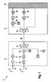
- FIG. 1 shows a block diagram of a receiving device 1 according to the invention with a first antenna 2 and a second antenna 3.
- the receiving device according to the invention according to FIG. 1 as a double receiving device, wherein also over two more outgoing number of antennas may be provided.
- the invention thus does not relate solely to a receiving device with two antennas.
- the embodiment is thus not limiting to the scope of protection. Instead of the two antennas, three, four or more antennas may be provided.
- the receiving device essentially consists of two sub-devices 4, 5, the sub-device 4 serving to condition the antenna signals, and the sub-system 5 serving as a receiving part of the device to which the antenna signals are supplied.
- the signal 6 received by the antenna 2 and to be forwarded is passed from the first sub-device 4 to the second sub-device 5 without frequency conversion.
- the signal 6 in the first sub-device can be filtered and / or amplified by means of a filter 7 and / or an amplifier 8.
- the thus possibly filtered and / or amplified signal 6 is fed via a frequency-selective in this example combiner 9 in the connection 10 between the first sub-device and the second sub-connection.
- the second antenna signal 11 of the second antenna 3 can be filtered and amplified by means of a filter 12 and / or amplifier 13 before it is mixed by means of a mixer 14 to an intermediate frequency.
- the mixed intermediate frequency signal (IF signal) is input to the connection 10 in addition to the non-mixed signal of the first antenna.
- the connection 10 may preferably be a cable or other electrical connection.
- the mixture to the intermediate frequency of the second signal 11 of the second antenna 3 is preferably carried out at the base of the second antenna or in the vicinity of one of the receiving antennas 2, 3 in the first sub-device 4.
- the signal is mixed to an intermediate frequency which is not in the received spectrum ,
- the two signals can be directed to the connection between the first sub-device and the second sub-device.
- the signal of the first antenna After passing through the frequency-selective splitter 15 in this example, the signal of the first antenna, which has not yet been mixed, is mixed in the mixer 16. Subsequently, the signals are further processed by means of the processing stages IF filter 17, amplifier / demodulator 18 and / or other subsequent stages 19.
- the device described above has between the two sub-devices 4,5 as subunits only an electrical connection 10, such as a cable o. on, by means of which both antenna signals are transmitted.
- an electrical connection 10 such as a cable o. on
- the variety of parts can be reduced and at the same time the susceptibility to interference can be reduced required interfaces and reduced by reducing the number of parts used. Also, this provides a weight reduction, which is particularly advantageous in the vehicle sector.
- the two mixers 14, 16 can be designed such that they have different intermediate frequencies or also have the same intermediate frequencies.
- both intermediate frequencies can be 10.7 MHz. In this case, there would be a cost advantage, since in this frequency range many standard components are offered, which could be used.
- Both antenna units can also receive the same frequencies, and yet two uncorrelated signals are available to the further signal processing, which signals are conducted via only one antenna line 10.
Landscapes
- Engineering & Computer Science (AREA)
- Computer Networks & Wireless Communication (AREA)
- Signal Processing (AREA)
- Input Circuits Of Receivers And Coupling Of Receivers And Audio Equipment (AREA)
- Radio Transmission System (AREA)
Claims (13)
- Dispositif de réception (1) pour recevoir et interpréter des signaux avec au moins deux antennes (2, 3), le dispositif (1) présentant deux sous-dispositifs (4, 5) qui sont reliés ensemble au moyen d'une liaison électrique (10), caractérisé en ce que les deux antennes (2, 3) ne sont reliées électriquement qu'avec le premier sous-dispositif (4), en ce qu'un signal (6) de la première antenne (2) est transmis sans conversion de fréquence du premier sous-dispositif (4) au deuxième sous-dispositif (5) par le biais de la liaison électrique (10) et un signal (11) de la deuxième antenne (3) est également transmis par le biais de la liaison électrique (10) du premier sous-dispositif (4) au deuxième sous-dispositif (5), avec une conversion de fréquence par un mélangeur de fréquences (14), en ce qu'une conversion de fréquence du premier signal (6) seulement est effectuée par un deuxième mélangeur de fréquences (16) dans le deuxième sous-dispositif (5), en ce que la liaison électrique (10) destinée à la transmission de signaux du premier sous-dispositif (4) vers le deuxième sous-dispositif (5) s'effectue par un seul câble, à savoir par un câble bipolaire ou un câble coaxial, et en ce que les signaux reçus (6, 11) se trouvent dans la même bande de fréquences de radiodiffusion ou même à la même fréquence.
- Dispositif de réception selon la revendication 1, caractérisé en ce que les signaux reçus sont rassemblés en un seul signal après le traitement dans le deuxième sous-dispositif (5).
- Dispositif de réception selon l'une des revendications précédentes, caractérisé en ce qu'une deuxième fréquence intermédiaire du deuxième mélangeur de fréquences (16) est au moins comparable ou égale à une première fréquence intermédiaire du premier mélangeur de fréquences (14).
- Dispositif de réception selon l'une des revendications 1 ou 2, caractérisé en ce qu'il existe une deuxième fréquence intermédiaire du deuxième mélangeur de fréquences (16) et une première fréquence intermédiaire du premier mélangeur de fréquences (14), l'une des fréquences intermédiaires choisies étant la bande de base.
- Dispositif de réception selon l'une des revendications précédentes, caractérisé en ce que le premier et/ou le deuxième signal (6, 11) est filtré et/ou amplifié dans le premier sous-dispositif (4) avant la transmission au deuxième sous-dispositif (5).
- Dispositif de réception selon l'une des revendications précédentes, caractérisé en ce qu'un moyen de filtrage (7, 12) à l'entrée du premier sous-dispositif (4) est réalisé sous la forme d'un filtre passe-bande et/ou un étage mélangeur du premier mélangeur de fréquences (14) est réalisé sous la forme d'un étage mélangeur de fréquence fixe qui convertit la totalité ou une partie de la bande dans une autre position de fréquence.
- Dispositif de réception selon l'une des revendications précédentes, caractérisé en ce que l'amplification réalisée dans le premier sous-dispositif peut être régulée en fonction du niveau du signal reçu.
- Dispositif de réception selon l'une des revendications précédentes, caractérisé en ce qu'une tension continue est utilisée pour l'alimentation électrique d'au moins l'un des sous-dispositifs (4, 5), la tension continue pouvant être acheminée de préférence par le biais de la liaison électrique (10) entre les deux sous-dispositifs.
- Dispositif de réception selon l'une des revendications précédentes, caractérisé en ce que des signaux de commande peuvent être acheminés par le biais de la liaison électrique (10) entre les deux sous-dispositifs (4, 5).
- Dispositif de réception selon l'une des revendications précédentes, caractérisé en ce que les au moins deux antennes (2, 3) forment une structure d'antenne commune.
- Dispositif de réception selon la revendication 10, caractérisé en ce que le signal de la première antenne (6) et le signal de la deuxième antenne (11) sont prélevés de la structure d'antenne.
- Dispositif de réception selon la revendication 11, caractérisé en ce qu'un trajet de signal du premier ou du deuxième signal (6, 11) est réalisé avec une adaptation d'impédance sélective.
- Dispositif de réception selon la revendication 12, caractérisé en ce que l'adaptation d'impédance sélective d'un trajet de signal est réalisée de telle sorte qu'il ne soutire pas d'énergie de l'autre trajet de signal.
Applications Claiming Priority (1)
| Application Number | Priority Date | Filing Date | Title |
|---|---|---|---|
| DE200710022227 DE102007022227A1 (de) | 2007-05-11 | 2007-05-11 | Empfangsvorrichtung |
Publications (3)
| Publication Number | Publication Date |
|---|---|
| EP1990923A2 EP1990923A2 (fr) | 2008-11-12 |
| EP1990923A3 EP1990923A3 (fr) | 2011-05-11 |
| EP1990923B1 true EP1990923B1 (fr) | 2012-05-23 |
Family
ID=39674466
Family Applications (1)
| Application Number | Title | Priority Date | Filing Date |
|---|---|---|---|
| EP20080102914 Not-in-force EP1990923B1 (fr) | 2007-05-11 | 2008-03-26 | Dispositif de réception |
Country Status (2)
| Country | Link |
|---|---|
| EP (1) | EP1990923B1 (fr) |
| DE (1) | DE102007022227A1 (fr) |
Family Cites Families (6)
| Publication number | Priority date | Publication date | Assignee | Title |
|---|---|---|---|---|
| DE3226980A1 (de) * | 1982-07-19 | 1984-01-19 | Siemens AG, 1000 Berlin und 8000 München | Empfangsanordnung fuer terrestrisches fernsehen und satellitenfernsehen und/oder rundfunk |
| NL8901460A (nl) * | 1989-06-08 | 1991-01-02 | Philips Nv | Ontvanger voor terrestriele am- en satelliet fm-tv-omroepsignalen. |
| GB9219486D0 (en) * | 1992-09-15 | 1992-10-28 | British Broadcasting Corp | Digital audio broadcasts |
| DE10115053A1 (de) | 2001-03-27 | 2002-10-24 | Bosch Gmbh Robert | Verfahren und Vorrichtung zur Unterdrückung von Multipath-Störungen bei einem Empfänger für elektromagnetische Wellen |
| WO2003103161A2 (fr) * | 2002-05-30 | 2003-12-11 | Koninklijke Philips Electronics N.V. | Systeme de reception et de traitement de frequences radio |
| US7650173B2 (en) * | 2005-10-06 | 2010-01-19 | Flextronics Ap, Llc | Combined antenna module with single output |
-
2007
- 2007-05-11 DE DE200710022227 patent/DE102007022227A1/de not_active Withdrawn
-
2008
- 2008-03-26 EP EP20080102914 patent/EP1990923B1/fr not_active Not-in-force
Also Published As
| Publication number | Publication date |
|---|---|
| DE102007022227A1 (de) | 2008-11-13 |
| EP1990923A3 (fr) | 2011-05-11 |
| EP1990923A2 (fr) | 2008-11-12 |
Similar Documents
| Publication | Publication Date | Title |
|---|---|---|
| DE60315917T2 (de) | Antenne mit Spiegelfrequenzunterdrückung | |
| WO2018149459A1 (fr) | Compensateur, circuit électronique pour faire fonctionner une antenne et dispositif d'antenne | |
| EP1701407A1 (fr) | Système de réception à antennes multiples dans véhicules | |
| EP1405370B1 (fr) | Ensemble de raccordement d'antenne, separateur de signaux d'antenne et procede pour reguler une frequence de reception | |
| DE102010041612B4 (de) | Empfangsanordnung eines Kraftfahrzeugs | |
| EP0128970A1 (fr) | Circuit à quatre accès pour une antenne de poursuite monopulse à microondes | |
| EP1990923B1 (fr) | Dispositif de réception | |
| EP0740434B1 (fr) | Système pour la distribution de programmes de télévision par satellite dans un système d'antenne collectif | |
| DE3543229C1 (de) | Hausverteilnetz fuer Einzel- und Gemeinschafts-Antennenanlagen | |
| DE102014223883B4 (de) | Mehrkanal-Drahtlosmikrofonsystem | |
| EP1832012B1 (fr) | Dispositif a diversite d'antenne | |
| DE3909685C2 (fr) | ||
| EP1076457B1 (fr) | Installation de réception de satellite avec boîte commutateur | |
| DE60115572T2 (de) | Verfahren und Schaltung eines Multibandempfänger in einem Mobilfunktelefon | |
| DE102005044620B4 (de) | Front-End-Modul für drahtlose Kommunikationsmittel | |
| EP2634936B1 (fr) | Système d'alimentation, en particulier destiné à la réception de programmes radio et/ou télévisés émis par satellite | |
| DE10219847A1 (de) | Verfahren sowie Vorrichtung zur Erzeugung zumindest eines Transponders in der Satelliten-Zwischenfrequenz-Ebene | |
| EP2573989B1 (fr) | Dispositif de suppression de signaux parasites haute fréquence | |
| EP3738214A1 (fr) | Systèmes de transport de signaux reçus de l'extérieur dans un véhicule automobile | |
| DE202009018162U1 (de) | Multischalter für Satelliten-Zwischenfrequenz-Verteilung | |
| EP0985269B1 (fr) | Reseau de distribution haute frequence a decouplage tres pousse | |
| DE10326751B3 (de) | Verfahren zum Empfang von Funksignalen durch eine Empfangsstation sowie entsprechende Empfangsstation | |
| DE102004040420A1 (de) | Antennenanordnung zum Empfangen terrestrischer Hochfrequenzsignale | |
| EP1881703A1 (fr) | Prise pour réseaux de télécommunication | |
| DE4329693A1 (de) | Satellitenfunkempfänger |
Legal Events
| Date | Code | Title | Description |
|---|---|---|---|
| PUAI | Public reference made under article 153(3) epc to a published international application that has entered the european phase |
Free format text: ORIGINAL CODE: 0009012 |
|
| AK | Designated contracting states |
Kind code of ref document: A2 Designated state(s): AT BE BG CH CY CZ DE DK EE ES FI FR GB GR HR HU IE IS IT LI LT LU LV MC MT NL NO PL PT RO SE SI SK TR |
|
| AX | Request for extension of the european patent |
Extension state: AL BA MK RS |
|
| PUAL | Search report despatched |
Free format text: ORIGINAL CODE: 0009013 |
|
| AK | Designated contracting states |
Kind code of ref document: A3 Designated state(s): AT BE BG CH CY CZ DE DK EE ES FI FR GB GR HR HU IE IS IT LI LT LU LV MC MT NL NO PL PT RO SE SI SK TR |
|
| AX | Request for extension of the european patent |
Extension state: AL BA MK RS |
|
| 17P | Request for examination filed |
Effective date: 20111111 |
|
| AKX | Designation fees paid |
Designated state(s): DE FR GB IT |
|
| GRAP | Despatch of communication of intention to grant a patent |
Free format text: ORIGINAL CODE: EPIDOSNIGR1 |
|
| GRAS | Grant fee paid |
Free format text: ORIGINAL CODE: EPIDOSNIGR3 |
|
| GRAA | (expected) grant |
Free format text: ORIGINAL CODE: 0009210 |
|
| AK | Designated contracting states |
Kind code of ref document: B1 Designated state(s): DE FR GB IT |
|
| REG | Reference to a national code |
Ref country code: GB Ref legal event code: FG4D Free format text: NOT ENGLISH |
|
| REG | Reference to a national code |
Ref country code: DE Ref legal event code: R096 Ref document number: 502008007252 Country of ref document: DE Effective date: 20120726 |
|
| PLBE | No opposition filed within time limit |
Free format text: ORIGINAL CODE: 0009261 |
|
| STAA | Information on the status of an ep patent application or granted ep patent |
Free format text: STATUS: NO OPPOSITION FILED WITHIN TIME LIMIT |
|
| 26N | No opposition filed |
Effective date: 20130226 |
|
| REG | Reference to a national code |
Ref country code: DE Ref legal event code: R097 Ref document number: 502008007252 Country of ref document: DE Effective date: 20130226 |
|
| PGFP | Annual fee paid to national office [announced via postgrant information from national office to epo] |
Ref country code: GB Payment date: 20150324 Year of fee payment: 8 |
|
| REG | Reference to a national code |
Ref country code: FR Ref legal event code: PLFP Year of fee payment: 9 |
|
| GBPC | Gb: european patent ceased through non-payment of renewal fee |
Effective date: 20160326 |
|
| PG25 | Lapsed in a contracting state [announced via postgrant information from national office to epo] |
Ref country code: GB Free format text: LAPSE BECAUSE OF NON-PAYMENT OF DUE FEES Effective date: 20160326 |
|
| REG | Reference to a national code |
Ref country code: FR Ref legal event code: PLFP Year of fee payment: 10 |
|
| REG | Reference to a national code |
Ref country code: FR Ref legal event code: PLFP Year of fee payment: 11 |
|
| PGFP | Annual fee paid to national office [announced via postgrant information from national office to epo] |
Ref country code: FR Payment date: 20190326 Year of fee payment: 12 Ref country code: IT Payment date: 20190321 Year of fee payment: 12 |
|
| PGFP | Annual fee paid to national office [announced via postgrant information from national office to epo] |
Ref country code: DE Payment date: 20190520 Year of fee payment: 12 |
|
| REG | Reference to a national code |
Ref country code: DE Ref legal event code: R119 Ref document number: 502008007252 Country of ref document: DE |
|
| PG25 | Lapsed in a contracting state [announced via postgrant information from national office to epo] |
Ref country code: DE Free format text: LAPSE BECAUSE OF NON-PAYMENT OF DUE FEES Effective date: 20201001 Ref country code: FR Free format text: LAPSE BECAUSE OF NON-PAYMENT OF DUE FEES Effective date: 20200331 |
|
| PG25 | Lapsed in a contracting state [announced via postgrant information from national office to epo] |
Ref country code: IT Free format text: LAPSE BECAUSE OF NON-PAYMENT OF DUE FEES Effective date: 20200326 |