EP1990937A1 - Procédé et appareil de chargement, de détection et de surveillance pour signal optique associé à un canal - Google Patents
Procédé et appareil de chargement, de détection et de surveillance pour signal optique associé à un canal Download PDFInfo
- Publication number
- EP1990937A1 EP1990937A1 EP06817867A EP06817867A EP1990937A1 EP 1990937 A1 EP1990937 A1 EP 1990937A1 EP 06817867 A EP06817867 A EP 06817867A EP 06817867 A EP06817867 A EP 06817867A EP 1990937 A1 EP1990937 A1 EP 1990937A1
- Authority
- EP
- European Patent Office
- Prior art keywords
- channel
- signal
- optical
- loading
- spread spectrum
- Prior art date
- Legal status (The legal status is an assumption and is not a legal conclusion. Google has not performed a legal analysis and makes no representation as to the accuracy of the status listed.)
- Ceased
Links
Images

Classifications
-
- H—ELECTRICITY
- H04—ELECTRIC COMMUNICATION TECHNIQUE
- H04B—TRANSMISSION
- H04B10/00—Transmission systems employing electromagnetic waves other than radio-waves, e.g. infrared, visible or ultraviolet light, or employing corpuscular radiation, e.g. quantum communication
- H04B10/07—Arrangements for monitoring or testing transmission systems; Arrangements for fault measurement of transmission systems
- H04B10/075—Arrangements for monitoring or testing transmission systems; Arrangements for fault measurement of transmission systems using an in-service signal
- H04B10/077—Arrangements for monitoring or testing transmission systems; Arrangements for fault measurement of transmission systems using an in-service signal using a supervisory or additional signal
- H04B10/0775—Performance monitoring and measurement of transmission parameters
-
- H—ELECTRICITY
- H04—ELECTRIC COMMUNICATION TECHNIQUE
- H04B—TRANSMISSION
- H04B2210/00—Indexing scheme relating to optical transmission systems
- H04B2210/07—Monitoring an optical transmission system using a supervisory signal
- H04B2210/072—Monitoring an optical transmission system using a supervisory signal using an overhead signal
-
- H—ELECTRICITY
- H04—ELECTRIC COMMUNICATION TECHNIQUE
- H04B—TRANSMISSION
- H04B2210/00—Indexing scheme relating to optical transmission systems
- H04B2210/07—Monitoring an optical transmission system using a supervisory signal
- H04B2210/074—Monitoring an optical transmission system using a supervisory signal using a superposed, over-modulated signal
Definitions
- the present invention relates to the technical field of optical communication, and particularly to a method and apparatus for loading, detecting, and monitoring channel-associated signals.
- optical devices greatly promotes the development of optical communications.
- WDM Wavelength Division Multiplexing
- optical amplifiers As the optical transmission technologies (e.g., coding, modulation, etc.) become matured, long-range and super long-range transmissions have emerged.
- commercial transmission without electric regenerator can achieve transmission of more than 2000 ⁇ 4000Km.
- an all-optical transmission network OTN has been put on the agenda.
- the all-optical transmission network has greatly reduced the cost and brings no similar "electronic bottleneck” effect that occurs in electric signal processing, and the processing capacity of the all-optical transmission network is not restricted by signal rate, protocol, or format, etc. Therefore, the all-optical transmission network is an ideal communication network.
- technologies of reconfigurable devices such as Wavelength Blocker (WB) and Wavelength Select Switch (WSS)
- WB Wavelength Blocker
- WSS Wavelength Select Switch
- ITU-T International Telecommunication Union-Standardization Sector proposes in G.709 an out-of-band control method, in which an out-of-band optical supervisory channel (OSC) is utilized to transmit information of different optical channels, thereby implementing management and maintenance of different optical signals.
- OSC optical supervisory channel
- the out-of-band OSC can only carry out routing and protective switching over optical signals, but cannot realize supervisory control over quality or performance of optical signals, and therefore it is unable to determine whether the quality of optical signals meets requirements.
- the out-of-band OSC only transmits part of overheads and it is unable to determine whether the rerouting of optical signals by the reconfigurable devices actually accomplishes channel selection actions specified for the optical signals; and in addition, the failure of the out-of-band OSC itself will also trigger processing on optical signals; although reliability of the out-of-band OSC can be increased by means of a backup strategy, that will bring additional cost and complexity.
- the power of the wavelength signal can be detected by detecting the power of the corresponding low-frequency interference signal; and information, such as optical signal-noise ratio (OSNR), on the corresponding wavelength signal can be calculated by measuring the overall optical power.
- OSNR optical signal-noise ratio
- this method can realize monitoring of the quality of the wavelength signal, it has some disadvantages as follows: 1. Different wavelengths must be identified with different frequencies, and the frequency interval must be greater than the frequency resolution of the monitoring point, as a result, the available identification signals are very limited; 2. Although the low-frequency interference signal has a relatively little effect on the main optical channel, it still has some effect on the quality of the wavelength signal; 3.
- the corresponding relationship between the wavelength signal and the low-frequency interference signal must be configured in advance; otherwise it will be difficult to know which channel of the wavelength signal is monitored; 4.
- the optical signals cannot carry channel-associated overhead; protective switching, other channel selection commands and other indication information must be settled through other methods.
- channel-associated overhead information is added at different transmitting points and is extracted at subsequent monitoring points.
- the overhead information is required to accomplish monitoring of quality of optical signals and carry channel-associated signaling, such as Automatic Protect Switch (APS) signaling for protective switching, Open Shortest Path First (OSPF) signaling for rerouting, and other information (e.g., source node ID and destination node ID, which are used to identify the source and termination of optical signals).
- APS Automatic Protect Switch
- OSPF Open Shortest Path First
- source node ID and destination node ID which are used to identify the source and termination of optical signals.
- the present invention provides a method and apparatus for loading, detecting, and monitoring channel-associated optical signals, so as to overcome the disadvantages in channel-associated monitoring and overhead transmission in the prior arts.
- the present invention puts forward a method for loading a channel-associated optical signal, including the following steps: 1) performing spectrum-spreading operation on the channel-associated signal, by a loading point, with a spread spectrum code corresponding to the loading point, to obtain a channel-associated identification signal of the loading point; 2) modulating a passing optical service signal, by the loading point, with the channel-associated identification signal, to obtain a modulated optical signal.
- An embodiment of the present invention provides a method for detecting a channel-associated optical signal, including the following steps: 1) splitting a optical signal from an upstream node, by a detecting point, and converting a split optical signal into an electric signal; 2) de-spreading the electric signal, by the detecting point, with a spread spectrum code corresponding to a loading point to be monitored, to obtain a channel-associated signal of the loading point to be monitored corresponding to the spread spectrum code.
- An embodiment of the present invention provides a method for monitoring a channel-associated optical signal, including the following steps: 1) spectrum-spreading the channel-associated signal, by a loading point, with a spread spectrum code corresponding to the loading point, to obtain a channel-associated identification signal of the loading point; 2) modulating a passing optical service signal, by the loading point, with the channel-associated identification signal, to obtain a modulated optical signal; 3) splitting the optical signal from an upstream node, by a detecting point, and converting a split optical signal into an electric signal; 4) de-spreading the electric signal, by the detecting point, with a spread spectrum code corresponding to the loading point to be monitored, to obtain the channel-associated signal of the loading point to be monitored corresponding to the spread spectrum code.
- An embodiment of the present invention provides a method for loading a channel-associated optical signal with negative feedback, including the following steps: 1) spectrum-spreading the channel-associated signal, by a loading point, with a spread spectrum code corresponding to the loading point, to obtain a channel-associated identification signal of the loading point; 2) modulating a passing optical service signal, by the loading point, with the channel-associated identification signal, to obtain a modulated optical signal; 3) splitting the optical signal, by a detecting point arranged meanwhile in the loading point, and converting a split optical signal into an electric signal; 4) de-spreading the electric signal, by the detecting point, with the spread spectrum code corresponding to the loading point, to obtain the channel-associated signal of the loading point, where the channel-associated signal is adapted to control modulation depth at the loading point.
- An embodiment of the present invention provides an apparatus for loading a channel-associated optical signal, including: a channel-associated signal generator, adapted to generate a channel-associated signal of a loading point; a spread spectrum code generator, adapted to generate a spread spectrum code of the loading point; a spectrum spreading unit, adapted to spectrum-spread the channel-associated signal with the spread spectrum code, to obtain a channel-associated identification signal; a loading unit, adapted to modulate a passing optical service signal with the channel-associated identification signal, to obtain a modulated optical signal.
- An embodiment of the present invention provides an apparatus for detecting a channel-associated optical signal, including: an optical splitter, coupled to an optical channel and adapted to split a modulated optical signal; a photoelectric conversion circuit, adapted to convert a split optical signal into an electric signal; a spread spectrum code generator, adapted to generate a spread spectrum code corresponding to a loading point to be detected; a de-spreading unit, adapted to de-spread an electric signal with a spread spectrum code; a channel-associated signal processing unit, adapted to detect a de-spread signal and process the signal according to a detection result.
- An embodiment of the present invention provides an apparatus for monitoring a channel-associated optical signal, including a loading device and a detecting device, wherein the loading device includes a channel-associated signal generating unit, a first spread spectrum code generator, a spectrum spreading unit, and a loading unit: the channel-associated signal generating unit is adapted to generate a channel-associated signal of a loading point, the first spread spectrum code generator is adapted to generate a spread spectrum code of a loading point, the spectrum spreading unit is adapted to spectrum-spread the channel-associated signal with the spread spectrum code to obtain a channel-associated identification signal, and the loading unit is adapted to modulate a passing optical service signal with the channel-associated identification signal to obtain a modulated optical signal; the detecting device includes an optical splitter, a photoelectric conversion circuit, a second spread spectrum code generator, a de-spreading unit, and a channel-associated signal processing unit: the optical splitter is coupled to an optical channel and adapted to split a modulated optical signal, the photoelectric conversion circuit is adapted to
- the present invention provides a method and an apparatus for loading channel-associated optical signals, in which, a channel-associated signal is identified with a spread spectrum code in electrical domain, and the spectrum width of channel-associated signal is spread, so that the power spectrum density of the channel-associated identification signal is reduced, thereby reducing the interference of the channel-associated identification signal to optical service signals.
- the channel-associated identification signal after being spectrum-spread has less interference to optical service signals; after being modulated to an optical service signal at respective loading points separately, the channel-associated identification signals are transmitted in the optical channel along with the optical signal.
- passing optical signals can be converted through photoelectric conversion, and the channel-associated identification signals are de-spread.
- the channel-associated signal of a corresponding loading point can be detected at a downstream detecting point; by processing the de-spread channel-associated signal, the working state of the upstream loading point and the state of network between the loading point and the detecting point can be judged according to the power component of the channel-associated signal, so as to attain the object of monitoring network performance by means of monitoring the channel-associated signal; in addition, the channel-associated signal can also carry overhead information, so that the transmission of channel-associated overhead information can be realized.
- the apparatus for monitoring channel-associated optical signals is provided so that the channel-associated signal from the upstream loading point can be obtained, the upstream loading point and the state of network can be monitored, a passing optical signal can be loaded with a channel-associated signal of a loading point, the loading point can be monitored at the downstream detecting points, and therefore the reliability of optical signal transmission can be improved.
- the channel-associated signal monitoring device can carry out feedback control over the optical signal modulated by the channel-associated signal monitoring device itself.
- the detecting device can judge whether the modulation depth is appropriate, according to the power component of the channel-associated signal in the modulated optical signal, and if the modulation depth is too low or too high, the loading device is controlled to re-modulate the optical service signal, thereby ensuring appropriate modulation depth of the optical service signals modulated by the channel-associated identification signal.
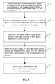
- Fig.1 is a schematic flow diagram of an embodiment of the present invention.
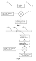
- Fig.2 is an architecture diagram of an apparatus for loading channel-associated optical signals according to an embodiment of the present invention
- Fig.3 is an architecture diagram of an apparatus for detecting channel-associated optical signals according to an embodiment of the present invention
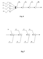
- Fig.4 is an architecture diagram of an apparatus for monitoring channel-associated optical signals according to an embodiment of the present invention.
- Fig.5 is an architecture diagram of a first embodiment of the present invention.
- Fig.6 is an architecture diagram of a second embodiment of the present invention.
- Fig.7 is an architecture diagram of a third embodiment of the present invention.
- a method for monitoring a channel-associated optical signal according to an embodiment of the present invention includes the following steps:
- Step 1 A loading point spectrum-spreads the channel-associated signal, with a spread spectrum code corresponding to the loading point, to obtain a channel-associated identification signal of the loading point;
- Step 2 The loading point modulate a passing optical service signal, with the channel-associated identification signal of the loading point, to obtain a modulated optical signal;
- Step 3 A detecting point splits the modulated optical signal, and converts a split optical signal into an electric signal
- Step 4 The detecting point filters the electric signal, and de-spreads the filtered electric signal with the spread spectrum code corresponding to the loading point to be detected by the detecting point;
- Step 5 The detecting point detects the de-spread signal and processes the de-spread signal according to the detection result.
- the loading and detecting in the above monitoring of channel-associated optical signal can be applied separately or in combination. Moreover, in actual applications, the filtering operation in the above Step 4 can be omitted.
- a channel associated signal may include the ID information of a loading point, the overhead information needed to be transmitted, a string of fixed, random, or designated bits or bytes, or any combination of them.
- a spread spectrum code includes unipolar spread spectrum codes, such as an orthogonal prime code, an optical orthogonal code, a quadratic congruence code, an extended prime code, an extended quadratic congruence code, a hybrid code, or an improved prime code, etc.
- Unipolar spread spectrum codes such as an orthogonal prime code, an optical orthogonal code, a quadratic congruence code, an extended prime code, an extended quadratic congruence code, a hybrid code, or an improved prime code, etc.
- the period of the channel-associated identification signal is greater than or equal to a preset times of the period of an optical service signal.
- the period of the channel-associated identification signal is greater than or equal to 10 times of the period of the optical service signals, so as to avoid the interference of the channel-associated identification signal to the optical service signals.
- the modulation depth of the optical service signal modulated by the channel-associated identification signal is controlled within the range from 3% to 5%.
- the modulation depth of the optical service signal modulated by the channel-associated identification signal can be up to 10%.
- the modulation depth of the optical service signal modulated with the channel-associated identification signal is smaller than or equal to a preset adjustment value, such as 10%, or approximately 0.5dB.
- the method further includes a step of processing the channel-associated signal before Step 1 as follows: assembling several channel-associated overheads into a frame, and inserting a fixed or variable frame header before the frame, or adding a cyclic redundancy check (CRC) byte in the frame, to carry out error correction for the channel-associated overheads.
- a step of processing the channel-associated signal before Step 1 as follows: assembling several channel-associated overheads into a frame, and inserting a fixed or variable frame header before the frame, or adding a cyclic redundancy check (CRC) byte in the frame, to carry out error correction for the channel-associated overheads.
- CRC cyclic redundancy check
- the method for modulating the optical service signal in Step 2 includes: connecting the optical service signal to an input port of an electrically-controlled variable optical attenuator (EVOA), utilizing the channel-associated identification signal to control the loss of the optical service signal, the intensity of the channel-associated identification signals being reflected by the variations of intensity of the optical service signals, thereby achieving the modulation of the optical service signal with the channel-associated identification signal; or connecting the optical service signal to an input port of a semiconductor optical amplifier (SOA), utilizing the channel-associated identification signals to control the gain of the optical service signal, superimposing the channel-associated identification signal with the optical service signal, therefore accomplishing the loading of the channel-associated identification signal.
- EVOA electrically-controlled variable optical attenuator
- SOA semiconductor optical amplifier
- the method can further include an analog-digital conversion operation after the filtering of the electric signal in Step 4, so that the digital signal can be processed in subsequent operations.
- the de-spreading of the channel-associated identification signal can be realized in the following two ways: 1. if there is only a single channel-associated identification signal, the channel-associated identification signal is de-spread with the spread spectrum code corresponding to the loading point to obtain the channel-associated signal of the loading point; 2. if the spectrum-spread channel-associated identification signals of a plurality of loading points are mixed, the filtered electric signal is split first, and then the split electric signals are de-spread in parallel, with the spread spectrum codes corresponding to the loading points, so as to obtain the channel-associated signals corresponding to the loading points respectively.
- the loading point can load the channel-associated identification signals to different wavelengths of optical service signals at the same time and transmit the mixed signals, and at a downstream detecting point, the channel-associated identification signals loaded at different loading points to the optical signals that are dropped at the downstream detecting point can be de-spread simultaneously, so as to improve the efficiency of monitoring of channel-associated signals.
- the method of detecting of the de-spread signals includes the following four approaches: 1. detecting the power component of the channel-associated signals in the de-spread signal, and judging whether the corresponding channel-associated signal exists; 2. detecting the power component of the channel-associated signals in the de-spread signals, and comparing the power component with a decision-threshold to judge whether the channel-associated signal exists; 3. detecting the power component of the channel-associated signal in the de-spread signal, and calculating the power component and OSNR of the corresponding service signal; 4. detecting the overhead of the channel-associated signal in the de-spread signal, and judging whether the corresponding channel-associated signal exists according to the overhead.
- An apparatus for loading channel-associated signals including a channel-associated signal generating unit 1, a first spread spectrum code generator 2, a spectrum spreading unit 3, and a loading unit 4.
- the first input end of the spectrum spreading unit 3 is connected to the output end of the channel-associated signal generating unit 1, and the second input end of the spectrum spreading unit 3 is connected to the output end of the first spread spectrum code generator 2.
- the loading unit 4 is connected in series to the optical channel 5, and the input end of the loading unit 4 is connected to the output end of the spectrum spreading unit 3.
- the loading unit 4 includes a modulator, a variable attenuator or an adjustable gain device.
- the variable attenuator can be an Electrically-controlled Variable Optical Attenuator (EVOA), and the adjustable gain device can be an SOA.
- EVOA Electrically-controlled Variable Optical Attenuator
- SOA SOA
- a device for detecting channel-associated signals including a photoelectric conversion circuit 7, a de-spreading unit 8, a second spread spectrum code generator 10, an optical splitter 6, a filter 11, and a channel-associated signal processing unit 9.
- the optical splitter 6 is coupled to the optical channel; the input end of the photoelectric conversion circuit 7 is connected to the output end of the optical splitter 6, and the output end of the photoelectric conversion circuit 7 is connected to the input end of the filter 11, and the output end of the filter 11 is connected through a analog-digital conversion circuit 12 to the first input end of the de-spreading unit 8; the second input end of the de-spreading unit 8 is connected to the output end of the second spread spectrum code generator 10, and the output end of the de-spreading unit 8 is connected to the input end of the channel-associated signal processing unit 9; the channel-associated signal processing unit 9 is adapted to detect signals output from the de-spreading unit 8.
- a de-multiplexer is arranged in series between the filter and the de-spreading unit to de-multiplex the electric signal filtered by the filter and then the de-multiplexed signals are output to a plurality pf de-spreading units, so that the de-spreading units can de-spread the de-multiplexed electric signals simultaneously according to the corresponding spread spectrum codes generated by the second spread spectrum code generator.
- the filter 11 and analog-digital conversion circuit 12 set forth above are optional devices.
- the present invention puts forward another method for monitoring channel-associated signals, i.e., a method for loading channel-associated signals having negative feedback, including the following steps:
- Step 1 A loading device spectrum-spreads a channel-associated signal, with a corresponding spread spectrum code, to obtain a channel-associated identification signal for the loading point;
- Step 2 The loading device modulates a passing optical service signal, with the channel-associated identification signal for the loading point, to obtain a modulated optical signal;
- Step 3 A detecting device splits the modulated optical signal, and convert a split optical signal into an electric signal
- Step 4 The detecting device filters the electric signal, and de-spreads the filtered electric signal, with the spread spectrum code corresponding to the loading device;
- Step 5 The detecting device detects the de-spread signals, and provides feedback to the loading device according to the detection result;
- Step 6 The loading device processes a passing optical service signal, according to the detection result.
- Step 4 the filtering operation in Step 4 is optional, and an analog-digital conversion operation can be performed on the electric signal after being filtered in Step 4, so that digital signals are processed in subsequent operations.
- Step 6 if the detecting device detects that the power component of the channel-associated signal in the de-spread signals is lower than the minimum power threshold, the loading device increases the modulation depth of the optical service signal modulated by the channel-associated identification signal; if the detecting device detects that the power component of the channel-associated signals in the de-spread signals is higher than the maximum power threshold, the loading device decreases the modulation depth of the optical service signal modulated by the channel-associated identification signal; if the detecting device detects that the power component of the channel-associated signals in the de-spread signals is between the minimum power threshold and the maximum power threshold, the loading device does not re-modulate the optical service signal.
- an apparatus for monitoring channel-associated signals including a loading device and a detecting device.
- the loading device includes a channel-associated signal generating unit 1, a first spread spectrum code generator 2, a spectrum spreading unit 3, and a loading unit 4.
- the channel-associated signal generating unit 1 is adapted to generate a channel-associated signal for the loading point;
- the first spread spectrum code generator 2 is adapted to generate a spread spectrum code for the loading point;
- the spectrum spreading unit 3 is adapted to spectrum spread the channel-associated signal with the spread spectrum code and obtain a channel-associated identification signal;
- the loading unit 4 is adapted to modulate a passing optical service signal with the channel-associated identification signal, to obtain a modulated optical signal.
- the detecting device includes an optical splitter 6, a photoelectric conversion circuit 7, a filter 11, a second spread spectrum code generator 10, a de-spreading unit 8, and a channel-associated signal processing unit 9;
- the optical splitter 6 is coupled to the optical channel and is adapted to split the modulated optical signal;
- the photoelectric conversion circuit 7 is adapted to convert a split optical signal into an electric signal;
- the filter 11 is adapted to filter the electric signals, mainly to filter off DC component and high frequency component;
- the analog-digital conversion circuit 12 is adapted to carry out analog-digital conversion on a filtered signal;
- the second spread spectrum code generator 10 is adapted to generate a spread spectrum code corresponding to a loading point;
- the de-spreading unit 8 is adapted to de-spread a filtered electric signal after being analog-digital converted, with the corresponding spread spectrum code;
- the channel-associated signal processing unit 9 is adapted to detect a de-spread signal and feed back a detection result to the loading unit 4.
- each of the units may be a site, or a function unit distributed in a site or among different sites.
- Each of the units may be a loading point or a detecting point.
- Each loading point is assigned with a unique identifiable spread spectrum code.
- the channel-associated identification signal can be detected and extracted at a monitoring point in downstream units through which the wavelength signals pass.
- the optical service signal at wavelength ⁇ 1 after passing through the loading point Al in the first unit A, forms the first optical signal;
- the optical service signal at wavelength ⁇ 2 after passing through the loading point A1 in the first unit A, forms the second optical signal.
- the first optical signal is dropped at the second unit B, while the second optical signal is transmitted to the fourth unit D.
- the channel-associated identification signal loaded at the first unit A can be detected by a detecting point B2 in the second unit B, a detecting point C2 in the third unit C, or a detecting point D2 in the fourth unit D.
- the channel-associated identification signal can be loaded at an upstream loading point, to notify a downstream site that an optical signal passes through the loading point.
- the downstream detecting point can de-spread, with a corresponding spread spectrum code, the channel-associated identification signal in the optical signal that is received or passes through the detecting point, and by processing the de-spread channel-associated signal, judge the working state of the upstream function unit and the network situation, so as to attain the object of monitoring network performance and further for transmitting overhead information.
- channel-associated identification signals are loaded to different optical signals, and the channel-associated identification signals are detected in the combined optical signals.
- each wavelength signal is loaded a different identifier, and in the optical multiplexing section, the identifier can be detected, so as to judge whether a wavelength signal exists or not and execute further operations such as controlling the power output from an amplifier; or the current operating condition of the network can be judged through the detection of power and OSNR of the wavelength signals, and it can be decided whether to execute further operations such as judging whether a wavelength blocking occurs and whether to carry out protection, etc.
- WDM Widelength Division Multiplexer
- channel-associated identification signals are loaded at a plurality of nodes, and each of the plurality of nodes has also a monitoring point.
- the overhead is loaded in each optical transmission section, and the overhead information is transmitted down along the entire link.
- the ASE component added in each transmission section can be ascertained, so as to learn about the optical signal deterioration in each transmission section and thereby notify the network maintenance personnel to check whether the transmission section is abnormal.
- the applications of the method provided in the present invention include, but is not limited to one or combination of the above two ways.
- the above two ways are used in combination when both the wavelength signals and the signals in optical multiplexing section (OMS) and optical transmission section (OTS) are required to be monitored.
- OMS optical multiplexing section
- OTS optical transmission section
Landscapes
- Physics & Mathematics (AREA)
- Electromagnetism (AREA)
- Engineering & Computer Science (AREA)
- Computer Networks & Wireless Communication (AREA)
- Signal Processing (AREA)
- Optical Communication System (AREA)
Applications Claiming Priority (2)
| Application Number | Priority Date | Filing Date | Title |
|---|---|---|---|
| CN 200610033905 CN100479352C (zh) | 2006-02-21 | 2006-02-21 | 光随路信号加载、监控的方法及装置 |
| PCT/CN2006/003131 WO2007095805A1 (fr) | 2006-02-21 | 2006-11-21 | Procédé et appareil de chargement, de détection et de surveillance pour signal optique associé à un canal |
Publications (2)
| Publication Number | Publication Date |
|---|---|
| EP1990937A1 true EP1990937A1 (fr) | 2008-11-12 |
| EP1990937A4 EP1990937A4 (fr) | 2011-05-04 |
Family
ID=37133526
Family Applications (1)
| Application Number | Title | Priority Date | Filing Date |
|---|---|---|---|
| EP06817867A Ceased EP1990937A4 (fr) | 2006-02-21 | 2006-11-21 | Procédé et appareil de chargement, de détection et de surveillance pour signal optique associé à un canal |
Country Status (4)
| Country | Link |
|---|---|
| US (2) | US8280248B2 (fr) |
| EP (1) | EP1990937A4 (fr) |
| CN (2) | CN100479352C (fr) |
| WO (1) | WO2007095805A1 (fr) |
Cited By (1)
| Publication number | Priority date | Publication date | Assignee | Title |
|---|---|---|---|---|
| EP3767840A4 (fr) * | 2018-03-12 | 2021-06-23 | ZTE Corporation | Procédé, dispositif et système de commande de changement de protection de réseau optique |
Families Citing this family (17)
| Publication number | Priority date | Publication date | Assignee | Title |
|---|---|---|---|---|
| US20060050751A1 (en) * | 2004-09-06 | 2006-03-09 | Fujitsu Limited | Optical transmission device for controlling optical level of wavelength multiplexed light and method thereof |
| CN100479352C (zh) * | 2006-02-21 | 2009-04-15 | 华为技术有限公司 | 光随路信号加载、监控的方法及装置 |
| CN101043271B (zh) * | 2007-04-26 | 2010-11-10 | 华为技术有限公司 | 一种光业务信号保护倒换方法、设备及系统 |
| CN101312376B (zh) * | 2007-05-25 | 2011-01-19 | 华为技术有限公司 | 检测光网络中部件级联顺序的方法、设备和系统 |
| CN101340238B (zh) * | 2007-07-05 | 2011-11-02 | 华为技术有限公司 | 光口之间连接关系的确定方法及装置 |
| CN102687426B (zh) * | 2009-08-31 | 2015-11-25 | 华为技术有限公司 | 带内光信噪比的检测方法及装置 |
| TWI651009B (zh) * | 2014-02-26 | 2019-02-11 | 日商新力股份有限公司 | 送訊裝置、收訊裝置及資訊處理方法 |
| CN105606910A (zh) * | 2014-11-21 | 2016-05-25 | 中兴通讯股份有限公司 | 光信噪比检测电路、装置及方法 |
| CN110326239B (zh) * | 2017-03-10 | 2020-11-17 | 华为技术有限公司 | 信号发射方法、信号接收方法、相关设备及系统 |
| CN109257093B (zh) * | 2017-07-14 | 2021-09-14 | 华为技术有限公司 | 一种光网络中光监控信道处理的方法和装置 |
| CN108429589B (zh) * | 2018-01-29 | 2020-02-07 | 清华大学 | 基于光谱分析的光网络的光源及光路径识别方法 |
| EP3672122B1 (fr) * | 2018-10-09 | 2024-06-19 | Huawei Technologies Co., Ltd. | Appareil et procédé d'étalonnage, et système de multiplexage par répartition en longueur d'onde |
| CN113452438B (zh) * | 2020-03-26 | 2022-06-17 | 烽火通信科技股份有限公司 | 一种用于波分复用系统的光信噪比的监测方法及装置 |
| CN113037678B (zh) * | 2021-02-26 | 2021-11-23 | 江苏科大亨芯半导体技术有限公司 | 标注光纤波长的方法 |
| EP4102726A1 (fr) * | 2021-06-09 | 2022-12-14 | Technische Universität Berlin | Procédé et système d'identification via des canaux utilisant des codes orthogonaux optiques |
| CN117336635A (zh) * | 2022-06-27 | 2024-01-02 | 中兴通讯股份有限公司 | 网络管理方法、网元、计算机可读介质 |
| IL308048B2 (en) * | 2023-10-26 | 2025-03-01 | Elbit Systems C4I & Cyber Ltd | Systems, subsystems and methods for coding and decoding of signals |
Family Cites Families (24)
| Publication number | Priority date | Publication date | Assignee | Title |
|---|---|---|---|---|
| IT1244150B (it) * | 1990-11-22 | 1994-07-08 | Face Standard Spa Alcatel | Metodo per misurazione di distanze e stazione trasmittente e ricevente per realizzare tale metodo. |
| US5513029A (en) | 1994-06-16 | 1996-04-30 | Northern Telecom Limited | Method and apparatus for monitoring performance of optical transmission systems |
| JPH09153862A (ja) * | 1995-11-30 | 1997-06-10 | Kokusai Denshin Denwa Co Ltd <Kdd> | 光増幅中継伝送システムの監視方法 |
| US5745274A (en) * | 1995-12-27 | 1998-04-28 | Lucent Technologies Inc. | Maintenance of optical networks |
| US6108113A (en) * | 1995-12-29 | 2000-08-22 | Mci Communications Corporation | Method and system for transporting ancillary network data |
| DE19713952C1 (de) * | 1997-04-04 | 1998-10-15 | Siemens Ag | Verfahren zur Übertragung von Zusatzdatensignalen und einem Nutzdatensignal über optische Verbindungen |
| DE19725714C1 (de) * | 1997-06-18 | 1998-12-17 | Deutsche Telekom Ag | Verfahren zur optischen Übertragung von Signalisierungs- und Steuerinformationen in optischen Netzen |
| JP3858451B2 (ja) * | 1998-06-03 | 2006-12-13 | Kddi株式会社 | 制御信号重畳装置 |
| JP4178617B2 (ja) * | 1998-10-14 | 2008-11-12 | 松下電器産業株式会社 | 光伝送システム、光送信装置及び光送信方法 |
| KR100317806B1 (ko) * | 1999-03-19 | 2001-12-22 | 서평원 | 확산스펙트럼 부호변조를 이용한 광신호 채널정보 감지장치 및방법 |
| DE19915091A1 (de) * | 1999-04-01 | 2000-10-05 | Univ Hannover | Verfahren zur Messung der Übertragungsgüte in optischen Netzen |
| US7599627B2 (en) * | 2001-05-31 | 2009-10-06 | Teradvance Communications, Llc | Method and system for a polarization mode dispersion tolerant optical homodyne detection system with optimized transmission modulation |
| US20030043437A1 (en) * | 2001-09-04 | 2003-03-06 | Stough Stephen A. | Subliminal coherent phase shift keyed in-band signaling of network management information in wavelength division multiplexed fiber optic networks |
| US7155122B2 (en) | 2001-10-05 | 2006-12-26 | Tropic Networks Inc. | Channel identification in communications networks |
| CA2358382C (fr) | 2001-10-05 | 2008-09-09 | Ping Wai Wan | Identification des canaux dans les reseaux de communication |
| US7158723B2 (en) | 2001-10-05 | 2007-01-02 | Tropic Networks Inc. | Channel identification in communications networks |
| US6731428B2 (en) * | 2001-11-21 | 2004-05-04 | Lucent Technologies Inc. | Pump monitoring and control in a fiber Raman amplifier |
| US7139486B2 (en) * | 2002-12-05 | 2006-11-21 | Tropic Networks Inc. | Method and apparatus for optical add/drop multiplexing in optical networks |
| KR100547715B1 (ko) * | 2003-03-12 | 2006-01-31 | 삼성전자주식회사 | 코드분할 다중화를 적용한 수동형 광 가입자 망 |
| US20050019040A1 (en) * | 2003-07-24 | 2005-01-27 | Trutna William R. | Optical communication system and method using spread-spectrum encoding |
| FR2859054B1 (fr) * | 2003-08-19 | 2006-12-29 | Cit Alcatel | Controle dynamique de perte de puissance dans une fibre optique par contrapropagation d'un canal de supervision |
| US20050074236A1 (en) * | 2003-10-07 | 2005-04-07 | Neptec Optical Solutions, Inc. | Optical network monitoring system |
| CN1283051C (zh) * | 2004-02-04 | 2006-11-01 | 烽火通信科技股份有限公司 | 一种光监控信息传输方法和系统 |
| CN100479352C (zh) * | 2006-02-21 | 2009-04-15 | 华为技术有限公司 | 光随路信号加载、监控的方法及装置 |
-
2006
- 2006-02-21 CN CN 200610033905 patent/CN100479352C/zh not_active Expired - Lifetime
- 2006-11-21 EP EP06817867A patent/EP1990937A4/fr not_active Ceased
- 2006-11-21 WO PCT/CN2006/003131 patent/WO2007095805A1/fr not_active Ceased
- 2006-11-21 CN CN200680012104.8A patent/CN101160758A/zh active Pending
-
2008
- 2008-08-21 US US12/195,717 patent/US8280248B2/en active Active
-
2011
- 2011-12-02 US US13/310,425 patent/US8891968B2/en active Active
Cited By (2)
| Publication number | Priority date | Publication date | Assignee | Title |
|---|---|---|---|---|
| EP3767840A4 (fr) * | 2018-03-12 | 2021-06-23 | ZTE Corporation | Procédé, dispositif et système de commande de changement de protection de réseau optique |
| US11418255B2 (en) | 2018-03-12 | 2022-08-16 | Zte Corporation | Method, device and system for controlling protection switching on optical network |
Also Published As
| Publication number | Publication date |
|---|---|
| CN100479352C (zh) | 2009-04-15 |
| WO2007095805A1 (fr) | 2007-08-30 |
| US8280248B2 (en) | 2012-10-02 |
| CN1852055A (zh) | 2006-10-25 |
| CN101160758A (zh) | 2008-04-09 |
| EP1990937A4 (fr) | 2011-05-04 |
| US20120076497A1 (en) | 2012-03-29 |
| US8891968B2 (en) | 2014-11-18 |
| US20090010641A1 (en) | 2009-01-08 |
Similar Documents
| Publication | Publication Date | Title |
|---|---|---|
| US8891968B2 (en) | Method and apparatus for loading, detecting, and monitoring channel-associated optical signals | |
| US10826601B2 (en) | Optical switch with path continuity monitoring for optical protection switching | |
| JP6005295B2 (ja) | 光信号対雑音比の検出方法、システム及び装置 | |
| US8787757B2 (en) | Optical communication network and supervisory control device | |
| US8218964B2 (en) | All optical 1+1 protection unit using sub-carrier modulation protocol | |
| US6317231B1 (en) | Optical monitoring apparatus and method for network provisioning and maintenance | |
| US5959749A (en) | Optical add/drop multiplexer/demultiplexer | |
| US6452701B1 (en) | Wavelength division multiplexing communications network supervisory system | |
| US9166726B2 (en) | Diverging device with OADM function and wavelength division multiplexing optical network system and method therefor | |
| US8554070B2 (en) | Optical transmission apparatus and optical attenuation amount control method | |
| US6404522B1 (en) | Optical communication method and system using wavelength division multiplexing | |
| US7327954B2 (en) | Optical signaling to share active channel information | |
| JP5414373B2 (ja) | 光アクセス網、光通信方法および光加入者装置 | |
| US9584249B2 (en) | Station-side terminal apparatus, optical access network, and communication method | |
| US6724953B2 (en) | Optical cross-connect apparatus, and its signal monitoring method | |
| JP6981014B2 (ja) | 受信装置及び監視制御信号検出方法 | |
| CN101278508B (zh) | 光网络中用于提供故障保护的系统和方法 | |
| JP4029661B2 (ja) | 光合分波方法及び装置 | |
| JP2018174366A (ja) | 通信装置および通信方法 | |
| WO2004077701A1 (fr) | Procede et dispositif servant a operer une commutation entre des circuits actif et auxiliaire de transmission optique | |
| JP2004040241A (ja) | 光伝送装置および光信号パス接続監視方法 | |
| WO2023238317A1 (fr) | Dispositif de transmission optique et procédé de gestion de transmission optique | |
| JP2005229387A (ja) | 光伝送装置 | |
| WO2002103937A1 (fr) | Systeme et appareil de telecommunication par fibre optique |
Legal Events
| Date | Code | Title | Description |
|---|---|---|---|
| PUAI | Public reference made under article 153(3) epc to a published international application that has entered the european phase |
Free format text: ORIGINAL CODE: 0009012 |
|
| 17P | Request for examination filed |
Effective date: 20080903 |
|
| AK | Designated contracting states |
Kind code of ref document: A1 Designated state(s): AT BE BG CH CY CZ DE DK EE ES FI FR GB GR HU IE IS IT LI LT LU LV MC NL PL PT RO SE SI SK TR |
|
| A4 | Supplementary search report drawn up and despatched |
Effective date: 20110404 |
|
| 17Q | First examination report despatched |
Effective date: 20111125 |
|
| DAX | Request for extension of the european patent (deleted) | ||
| REG | Reference to a national code |
Ref country code: DE Ref legal event code: R003 |
|
| STAA | Information on the status of an ep patent application or granted ep patent |
Free format text: STATUS: THE APPLICATION HAS BEEN REFUSED |
|
| 18R | Application refused |
Effective date: 20161104 |