EP1990962A2 - Procédé et appareil pour la retransmission de signaux de diffusion à entrées et sorties multiples (MIMO) - Google Patents
Procédé et appareil pour la retransmission de signaux de diffusion à entrées et sorties multiples (MIMO) Download PDFInfo
- Publication number
- EP1990962A2 EP1990962A2 EP08155891A EP08155891A EP1990962A2 EP 1990962 A2 EP1990962 A2 EP 1990962A2 EP 08155891 A EP08155891 A EP 08155891A EP 08155891 A EP08155891 A EP 08155891A EP 1990962 A2 EP1990962 A2 EP 1990962A2
- Authority
- EP
- European Patent Office
- Prior art keywords
- mimo broadcasting
- broadcasting signal
- mimo
- cable
- signal
- Prior art date
- Legal status (The legal status is an assumption and is not a legal conclusion. Google has not performed a legal analysis and makes no representation as to the accuracy of the status listed.)
- Withdrawn
Links
Images


Classifications
-
- H—ELECTRICITY
- H04—ELECTRIC COMMUNICATION TECHNIQUE
- H04B—TRANSMISSION
- H04B7/00—Radio transmission systems, i.e. using radiation field
- H04B7/02—Diversity systems; Multi-antenna system, i.e. transmission or reception using multiple antennas
-
- H—ELECTRICITY
- H04—ELECTRIC COMMUNICATION TECHNIQUE
- H04L—TRANSMISSION OF DIGITAL INFORMATION, e.g. TELEGRAPHIC COMMUNICATION
- H04L25/00—Baseband systems
- H04L25/02—Details ; arrangements for supplying electrical power along data transmission lines
- H04L25/20—Repeater circuits; Relay circuits
-
- H—ELECTRICITY
- H04—ELECTRIC COMMUNICATION TECHNIQUE
- H04H—BROADCAST COMMUNICATION
- H04H20/00—Arrangements for broadcast or for distribution combined with broadcast
- H04H20/02—Arrangements for relaying broadcast information
-
- H—ELECTRICITY
- H04—ELECTRIC COMMUNICATION TECHNIQUE
- H04H—BROADCAST COMMUNICATION
- H04H20/00—Arrangements for broadcast or for distribution combined with broadcast
- H04H20/28—Arrangements for simultaneous broadcast of plural pieces of information
- H04H20/33—Arrangements for simultaneous broadcast of plural pieces of information by plural channels
-
- H—ELECTRICITY
- H04—ELECTRIC COMMUNICATION TECHNIQUE
- H04H—BROADCAST COMMUNICATION
- H04H20/00—Arrangements for broadcast or for distribution combined with broadcast
- H04H20/65—Arrangements characterised by transmission systems for broadcast
- H04H20/76—Wired systems
- H04H20/77—Wired systems using carrier waves
-
- H—ELECTRICITY
- H04—ELECTRIC COMMUNICATION TECHNIQUE
- H04L—TRANSMISSION OF DIGITAL INFORMATION, e.g. TELEGRAPHIC COMMUNICATION
- H04L12/00—Data switching networks
- H04L12/02—Details
- H04L12/16—Arrangements for providing special services to substations
- H04L12/18—Arrangements for providing special services to substations for broadcast or conference, e.g. multicast
-
- H—ELECTRICITY
- H04—ELECTRIC COMMUNICATION TECHNIQUE
- H04W—WIRELESS COMMUNICATION NETWORKS
- H04W4/00—Services specially adapted for wireless communication networks; Facilities therefor
- H04W4/06—Selective distribution of broadcast services, e.g. multimedia broadcast multicast service [MBMS]; Services to user groups; One-way selective calling services
Definitions
- the present invention relates to a method and apparatus for re-transmitting multi-input multi-output (MIMO) broadcasting signals, and more particularly, to a method and apparatus for efficiently transmitting MIMO broadcasting signals from a receiver to a receiving terminal by using an existing cable without installing an additional cable.
- MIMO multi-input multi-output
- a multi-input multi-output (MIMO) transmitting method is applicable to various types of data receiving/transmitting, because the MIMO transmitting method improves a data transmission rate while using the same bandwidth.
- the MIMO transmitting method may be applied to terrestrial broadcasting signal receiving/transmitting.
- the MIMO broadcasting signals transmitted from a plurality of antennas are received by a plurality of antennas, and the received MIMO broadcasting signals are output through a receiving terminal by a MIMO receiver decoding the received MIMO broadcasting signals.
- FIGS. 1A and 1B briefly illustrate a MIMO broadcasting transmitter 101 and a MIMO broadcasting receiver 121, respectively, which transmit/receive broadcasting signals by applying a MIMO transmitting/receiving method.
- the MIMO broadcasting transmitter 101 illustrated in FIG. 1A includes a scrambler 103, a forward error correction (FEC) encoder 105, a stream parser 107, modulators 109 and 111, radio frequency (RF) up-converters 113 and 115, and multi-antennas 117 and 119.
- FEC forward error correction
- RF radio frequency
- Audio/video (AV) signals input to the MIMO broadcasting transmitter 101 are sequentially processed through each compositional block of the MIMO broadcasting transmitter 101, transformed to a predetermined frequency domain, and transmitted to the MIMO broadcasting receiver 121.
- AV Audio/video
- the scrambler 103 randomizes an input AV data packet so that signal energies are evenly distributed over an entire band.
- the FEC encoder 105 corrects channel errors.
- the stream parser 107 maps the broadcasting signals into each antenna of the multi-antennas 117 and 119.
- Each one of the modulators 109 and 111 modulates the signals mapped to each antenna.
- the RF up-converters 113 and 115 up-convert the modulated signals mapped to each antenna.
- the multi-antennas 117 and 119 transmit the up-converted signals to a broadcasting receiver.
- the MIMO broadcasting receiver 121 illustrated in FIG. 1B includes multi-antennas 123 and 125, RF down-converters 127 and 129, demodulators 131 and 133, a MIMO detector 135, an FEC decoder 137, and a de-scrambler 139.
- the MIMO broadcasting receiver 121 receives the transmitted broadcasting signals by using the multi-antennas 123 and 125.
- Each one of the multi-receiving-antennas 123 and 125 receives all of a plurality of RF transmitting signals, according to its characteristic as a terrestrial broadcasting channel.
- demodulation and decoding cannot be performed separately for each antenna, but all receiving antennas combine received signals and restore the signals to original signals.
- the MIMO broadcasting receiver 121 performs an inverse process of the MIMO broadcasting transmitter 101, thereby restoring original signals.
- the multi-antennas 123 and 125 receive the signals transmitted from the transmitter and transfer them to the RF down-converters 127 and 129.
- the RF down-converters 127 and 129 down-convert the signals transferred from the multi-antennas 123 and 125.
- the demodulators 131 and 133 demodulate the signals down-converted for each antenna.
- the MIMO detector 135 restores data by using the signals demodulated for each antenna as the input.
- the MIMO detector 135 restores the original signals by combining the signals received in the receiving antenna and determines an optimal transmitting symbol by using a characteristic of a channel of the signal received in each antenna.
- the MIMO detector 135 can be designed in various forms, but in general, it may be embodied in the form of a detector having a maximum likelihood (ML) performance.
- the FEC decoder 137 corrects data errors which may occur while restoring the data of the MIMO detector 135, and finally, restores an AV broadcasting signal which is the same as a transmitting broadcasting signal.
- the de-scrambler 139 processes the error-corrected AV broadcasting signal in an inverse process of the process performed in the scrambler 103, and restores the original signal.
- the number of antennas in the receiver are generally equal to or greater than the number of antennas in the transmitter.
- the number of antennas in the receiver may be smaller than the number of antennas in the transmitter.
- the received signal is a plurality of the RF signals including data streams that are different from each other.
- the plurality of the RF signals is transmitted to the same frequency band at once, thereby improving a transmission rate of all data while using the same channel bandwidth.
- re-transmitting the MIMO broadcasting signal according to an embodiment of the present invention is different from a diversity technique improving a signal-to-noise ratio (SNR) in a receiver by transmitting/receiving the same RF signal to/from the multi-antenna.
- SNR signal-to-noise ratio
- the method of transmitting/receiving the MIMO broadcasting signal has been selected for various recent wireless communication standards (for example, wireless LAN-IEEE 802.11n, Wibro-IEEE 802.16e), which is evaluated as a significant technique that improves a data transmission rate in the same frequency bandwidth.
- Such a method of transmitting/receiving the MIMO broadcasting signal may be used for terrestrial broadcasting allowing a data transmission rate suitable for transmitting broadcasting signals above a high-density (HD) level.
- HD high-density
- LAN wireless local area network
- Wibro Wibro system employing an MIMO technique
- a problem occurs in signal transmission between a receiving antenna and a terminal (for example, a TV set) via a cable.
- a method of receiving a broadcasting signal from an antenna and transmitting to a terminal will now be described in detail.
- the method of receiving a broadcasting signal from an antenna and transmitting to a terminal can be categorized into 1) receiving a signal with an exterior multi-antenna and transmitting the signal via a cable to a terminal, 2) directly receiving the signal with an interior multi-receiving-antenna attached to the terminal, and 3) a cable broadcasting station which receives terrestrial broadcasting re-transmitting the signal to a user's terminal via the cable.
- Method 2) of directly receiving the signal with an interior multi-receiving-antenna attached to the terminal is the same as a method selected for a wireless LAN or a Wibro terminal.
- a problem with this method is a decrease in a receiving capability caused by using the interior antenna.
- an additional cable should be installed.
- a plurality of cables is required because a plurality of RF signals have to be transmitted to a terminal for a MIMO signal transmission.
- most of current installed cables are single cables, and therefore it is difficult to transmit MIMO signals.
- the present invention provides a method and apparatus for re-transmitting multi-input multi-output (MIMO) broadcasting signals, which efficiently transmit a plurality of radio frequency (RF) signals when transmitting the MIMO broadcasting signal to a receiving terminal via a single cable.
- MIMO multi-input multi-output
- a method of re-transmitting a MIMO broadcasting signal including restoring an original signal by receiving a MIMO broadcasting signal via a multi-antenna; re-modulating the restored MIMO broadcasting signal; transmitting the re-modulated MIMO broadcasting signal to a receiving terminal via a cable; and demodulating the transmitted MIMO broadcasting signal in the receiving terminal.
- the operation of re-modulating the restored MIMO broadcasting signal may vary according to at least one of a data transmission rate of a MIMO broadcasting signal, a capacity of a cable, and a transmission method of the MIMO broadcasting signal via a cable.
- the MIMO broadcasting signal may be transmitted via one cable channel, and if the data transmission rate of a MIMO broadcasting signal is too large to be covered by one cable channel, the MIMO broadcasting signal may be transmitted via a plurality of cable channels.
- the MIMO broadcasting signal may be transmitted via one cable, if the capacity of a cable is too small to cover a transmission of the MIMO broadcasting signal, the MIMO broadcasting signal may be transmitted via a plurality of cables.
- the transmission method of the MIMO broadcasting signal is a method transmitting the signal by classifying broadcasting data
- data in a particular class may be selectively transmitted via a cable.
- a computer-readable medium having embodied thereon a computer program for executing the methods of re-transmitting the MIMO broadcasting signals.
- an apparatus for re-transmitting a MIMO broadcasting signal including a MIMO broadcasting receiver restoring an original signal by receiving the MIMO broadcasting signal via a multi-antenna; a re-modulator re-modulating the restored MIMO broadcasting signal; and a receiving terminal receiving and demodulating the re-modulated MIMO broadcasting signal via a cable.
- the constitution of the re-modulator may be changed according to at least one of a data transmission rate of a MIMO broadcasting signal, a capacity of a cable, and a transmission method of the MIMO broadcasting signal via a cable.
- the re-modulator may include a preprocessor re-packetizing the MIMO broadcasting signal input from the MIMO broadcasting receiver; a forwarded error correction (FEC) encoder correcting re-transmission errors of the MIMO broadcasting signal; a modulator re-modulating the MIMO broadcasting signal; and a RF up-converter up-converting the re-modulated MIMO broadcasting signal to an RF frequency band usable in a cable.
- FEC forwarded error correction
- the re-modulator may include a preprocessor re-packetizing the MIMO broadcasting signal input from the MIMO broadcasting receiver; an FEC encoder correcting re-transmission errors of the MIMO broadcasting signal; a stream parser mapping the MIMO broadcasting signal to a plurality of cables; a plurality of modulators re-modulating each signal of the plurality of the parsed MIMO broadcasting signals; a plurality of RF up-converters up-converting the plurality of the re-modulated MIMO broadcasting signal to an RF frequency band usable in the plurality of cables.
- the re-modulator may include a stream retriever selectively extracting data in a particular class from among the MIMO broadcasting signals input from the MIMO broadcasting receiver; a preprocessor re-packetizing the extracted MIMO broadcasting signal; an FEC encoder correcting re-transmission errors of the MIMO broadcasting signal; a modulator re-modulating the MIMO broadcasting signal; and an RF up-converter up-converting the re-modulated MIMO broadcasting signal to an RF frequency band usable in the cable.
- the extracted data in a particular class may be data having a low picture quality.
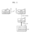
- FIG. 2 illustrates a broadcasting system re-transmitting multi-input multi-output (MIMO) broadcasting signals from a broadcasting receiver when transmitting/receiving MIMO broadcasting signals between a MIMO broadcasting transmitter 201 and a MIMO broadcasting receiver 203.
- MIMO multi-input multi-output
- the MIMO broadcasting transmitter 201 is an apparatus in a broadcasting station transmitting terrestrial broadcasting signals by using a multi-antenna.
- a detailed explanation of a structure of the MIMO broadcasting transmitter 201 was previously explained with reference to the prior art, and therefore a detailed explanation thereof will be omitted here.
- the MIMO broadcasting receiver 203 receives MIMO signals by using an exterior multi-antenna at home or at a cable broadcasting station, and then restores a broadcasting signal.
- a detailed explanation of a structure of the MIMO broadcasting receiver 203 was also previously explained with reference to the prior art, and therefore a detailed explanation thereof will be omitted here.
- a data re-modulator 205 re-modulates the restored broadcasting signal to a signal suitable for cable re-transmission.
- a terminal for example, a TV set
- FIG. 3 is a flowchart illustrating a method of re-transmitting MIMO broadcasting signals from a broadcasting receiver when transmitting/receiving MIMO broadcasting signals between a MIMO broadcasting transmitter and a MIMO broadcasting receiver.
- MIMO broadcasting signals are received via a multi-antenna and the original signal is restored (operation S301).
- the restored MIMO broadcasting signal is re-modulated (operation S303).
- the re-modulated MIMO broadcasting signal is transmitted to a receiving terminal via a cable (operation S305).
- the transmitted MIMO broadcasting signal is demodulated in the receiving terminal (operation S307).
- the restoring of the original signal by receiving the MIMO broadcasting signal via a multi-antenna restores the original signal by performing an inverse process of the process performed by the MIMO broadcasting transmitter.
- the signal transmitted from the transmitter is received for each antenna and down-converted, and the signal down-converted for each antenna is demodulated.
- data is restored by using the input signal demodulated for each antenna.
- the optimal transmission symbol is determined by using a characteristic of a channel of the signal received in the antenna.
- the original audio/video (AV) signal is generated by processes, such as forward error correction (FEC) decoding which restores an AV signal that is the same as the transmitted signal by correcting data errors that might occur while restoring data or descrambling which restores an original signal by performing an inverse process of the process in which the AV signal was processed in a scrambler.
- FEC forward error correction
- re-modulating of the MIMO broadcasting signal may be executed in various ways according to a transmission rate of a broadcasting signal, a status of a cable channel (a number of users using a cable channel, a cable capability, a length of a cable, the number of cables, and a quality of a cable), and a transmission method of a broadcasting signal.
- FIG. 4 illustrates a structure of a re-modulator 403 employing a method of transmitting MIMO broadcasting signals via a single cable channel, when a data transmission rate of a MIMO broadcasting signal is small enough to be covered by one cable channel or a capacity of a cable is large enough to cover a MIMO broadcasting signal transmission.
- the re-modulator 403 employing the above-described method includes a preprocessor 405 re-packetizing a MIMO broadcasting signal input from a MIMO broadcasting receiver 401, an FEC encoder 407 correcting re-transmission errors of the MIMO broadcasting signal, a modulator 409 re-modulating the MIMO broadcasting signal, and a radio frequency (RF) up-converter 411 up-converting the re-modulated MIMO broadcasting signal to a RF frequency band which is usable in a cable.
- RF radio frequency
- quadrature amplitude modulation (QAM) method which is widely applied in digital cable broadcasting.
- the signals may be re-transmitted to 256-QAM on a cable when re-transmitting.
- the data re-modulator 403 executes processes, such as preprocessing which re-packetizes the signal to make it easy to re-transmit on a cable, FEC encoding which corrects re-transmission errors, and QAM modulation (modulating 16-QAM to 256-QAM), and then up-converts the signal to an RF frequency band that is usable in a cable.
- processes such as preprocessing which re-packetizes the signal to make it easy to re-transmit on a cable, FEC encoding which corrects re-transmission errors, and QAM modulation (modulating 16-QAM to 256-QAM), and then up-converts the signal to an RF frequency band that is usable in a cable.
- FIG. 5 illustrates a structure of a re-modulator 503 employing a method of transmitting MIMO broadcasting signals via a plurality of cable channels, when a data transmission rate of a MIMO broadcasting signal is too large to be covered by one cable channel or a capacity of a cable is too small to cover a MIMO broadcasting signal.
- the re-modulator 503 employing the method includes a preprocessor 505 re-packetizing a MIMO broadcasting signal input from a MIMO broadcasting receiver 501, an FEC encoder 507 correcting re-transmission errors of the MIMO broadcasting signal, a stream parser 509 mapping the MIMO broadcasting signal to a plurality of cables, a plurality of modulators 511 and 513 re-modulating each signal of the plurality of parsed MIMO broadcasting signals, and a plurality of RF up-converters 515 and 517 up-converting the plurality of the re-modulated MIMO broadcasting signals to an RF frequency band usable in a cable.
- a data re-modulator executes FEC encoding on the MIMO broadcasting signal input from the MIMO broadcasting receiver, attempts streaming parsing, and separates the MIMO broadcasting signal into a plurality of data streams. Then, the data re-modulator re-transmits the signal by performing QAM modulation (modulating 64-QAM to 4096-QAM) and RF up-conversion for each data stream.
- QAM modulation modulating 64-QAM to 4096-QAM
- RF up-conversion for each data stream.
- a plurality of RF channels is selected on a cable, and the channels should be transmitted to a data demodulator in a terminal (for example, a TV set) without interference. In this case, a frequency bandwidth being used is doubled.
- FIG. 6 illustrates a structure of a re-modulator 603 employing a method of transmitting MIMO broadcasting signals by classifying the MIMO broadcasting signals.
- the re-modulator 603 employing the method includes a stream retriever 605 selectively extracting data in a particular class from among MIMO broadcasting signals input from a MIMO broadcasting receiver 601, a preprocessor 607 re-packetizing the extracted MIMO broadcasting signal, an FEC encoder 609 correcting re-transmission errors of the MIMO broadcasting signal, a modulator 611 re-modulating the MIMO broadcasting signal, and an RF up-converter 613 up-converting the re-modulated MIMO broadcasting signal to an RF frequency band usable in a cable.
- FIG. 7 illustrates a broadcasting signal (a bit stream) before and after re-modulation by the re-modulator 603 illustrated in FIG. 6 .
- bit-streams of AV data having a low picture quality and bit-streams of AV data having a high picture quality are transmitted via a bandwidth of 6 Mhz, if broadcasting data is classified and transmitted, and if there is no problem in transmitting only a particular class, data in a particular class (for example, AV data having a low picture quality) may be selected for re-transmission.
- a plurality of RF signals transmitted via a plurality of antennas is received/demodulated and re-modulated. Accordingly, an RF signal can be efficiently transmitted via a cable by modulating a plurality of RF signals to an RF signal.
- high quality high-density (HD) broadcasting by using an existing cable and a receiving terminal such as a TV set without installing an additional cable.
Landscapes
- Engineering & Computer Science (AREA)
- Signal Processing (AREA)
- Computer Networks & Wireless Communication (AREA)
- Multimedia (AREA)
- Power Engineering (AREA)
- Radio Transmission System (AREA)
- Input Circuits Of Receivers And Coupling Of Receivers And Audio Equipment (AREA)
Applications Claiming Priority (1)
| Application Number | Priority Date | Filing Date | Title |
|---|---|---|---|
| KR1020070044696A KR20080099067A (ko) | 2007-05-08 | 2007-05-08 | Mimo 방송 신호의 재전송 방법 및 장치 |
Publications (2)
| Publication Number | Publication Date |
|---|---|
| EP1990962A2 true EP1990962A2 (fr) | 2008-11-12 |
| EP1990962A3 EP1990962A3 (fr) | 2014-08-06 |
Family
ID=39734122
Family Applications (1)
| Application Number | Title | Priority Date | Filing Date |
|---|---|---|---|
| EP08155891.8A Withdrawn EP1990962A3 (fr) | 2007-05-08 | 2008-05-08 | Procédé et appareil pour la retransmission de signaux de diffusion à entrées et sorties multiples (MIMO) |
Country Status (2)
| Country | Link |
|---|---|
| EP (1) | EP1990962A3 (fr) |
| KR (1) | KR20080099067A (fr) |
Cited By (1)
| Publication number | Priority date | Publication date | Assignee | Title |
|---|---|---|---|---|
| WO2014135412A1 (fr) | 2013-03-07 | 2014-09-12 | Sony Corporation | Appareil de réception mimo, et appareil de prétraitement mimo |
Family Cites Families (4)
| Publication number | Priority date | Publication date | Assignee | Title |
|---|---|---|---|---|
| US5923642A (en) * | 1997-07-11 | 1999-07-13 | Viacom International, Inc. | Apparatus and method for using forward error correction setting to enable simultaneous use of multiple modulation systems on terrestrial distribution networks |
| CA2416790A1 (fr) * | 2000-08-01 | 2002-02-07 | Broadlogic Network Technologies | Architectcure de distribution de signaux video/audio/de donnees |
| US7954127B2 (en) * | 2002-09-25 | 2011-05-31 | The Directv Group, Inc. | Direct broadcast signal distribution methods |
| US8549565B2 (en) * | 2005-04-01 | 2013-10-01 | The Directv Group, Inc. | Power balancing signal combiner |
-
2007
- 2007-05-08 KR KR1020070044696A patent/KR20080099067A/ko not_active Ceased
-
2008
- 2008-05-08 EP EP08155891.8A patent/EP1990962A3/fr not_active Withdrawn
Cited By (4)
| Publication number | Priority date | Publication date | Assignee | Title |
|---|---|---|---|---|
| WO2014135412A1 (fr) | 2013-03-07 | 2014-09-12 | Sony Corporation | Appareil de réception mimo, et appareil de prétraitement mimo |
| CN105191197A (zh) * | 2013-03-07 | 2015-12-23 | 索尼公司 | Mimo接收设备和mimo预处理设备 |
| US9866287B2 (en) | 2013-03-07 | 2018-01-09 | Sony Corporation | MIMO receiving apparatus and MIMO preprocessing apparatus |
| CN105191197B (zh) * | 2013-03-07 | 2018-12-07 | 索尼公司 | Mimo接收设备和mimo预处理设备 |
Also Published As
| Publication number | Publication date |
|---|---|
| EP1990962A3 (fr) | 2014-08-06 |
| KR20080099067A (ko) | 2008-11-12 |
Similar Documents
| Publication | Publication Date | Title |
|---|---|---|
| US7577213B2 (en) | Hierarchical 8PSK performance | |
| CA2605444C (fr) | Procede et systeme de modulation et demodulation hierarchiques de radio numerique | |
| US6396803B2 (en) | Modulation methods and structures for wireless communication systems and transceivers | |
| CN105191197B (zh) | Mimo接收设备和mimo预处理设备 | |
| WO2005029737A2 (fr) | Emission radio de video de haute qualite | |
| Henarejos et al. | Dual polarized modulation and reception for next generation mobile satellite communications | |
| US20220368413A1 (en) | Transmodulation for a multi-beam satellite communication system | |
| US6968494B2 (en) | Method and apparatus for adaptively coding a data signal | |
| US8670368B2 (en) | Broadcast retransmitting method, broadcast retransmitting apparatus, replay apparatus, and broadcast retransmitting system using the same | |
| KR101887424B1 (ko) | Acm 기반의 사이멀캐스트 송수신 장치 및 방법 | |
| KR101350501B1 (ko) | 중계장치에 있어서의 신호처리 방법 | |
| EP1990962A2 (fr) | Procédé et appareil pour la retransmission de signaux de diffusion à entrées et sorties multiples (MIMO) | |
| EP2306679A1 (fr) | Démodulation tólerante aux bruit de phase et erreur de fréquence pour MoCA | |
| Morello et al. | DVB‐S2X: extending DVB‐S2 flexibility for core markets and new applications | |
| CN103237242B (zh) | 车载mimo型的dvb-t接收机 | |
| US20110033011A1 (en) | Methods and apparatuses relating to multi-resolution transmissions with mimo scheme | |
| CN1281061C (zh) | 双向通信设备和信号处理方法 | |
| EP0993703B1 (fr) | Suppression du brouillage resultant d'une polarisation opposee dans une communication par satellite | |
| KR20020005065A (ko) | 위성인터넷 데이터 케이블 연동시스템을 이용한 복합위성-케이블 인터넷 네트워크 | |
| Ito et al. | Field Trial of 4× 4 TDD-SVD-MIMO system with rank adaptation | |
| WO2023139696A1 (fr) | Système et procédé de communication sans fil et dispositif sans fil | |
| CN103237182A (zh) | Mimo型的dvb-t发射机 | |
| Faraj et al. | Mobile TV delivery enhancement using hierarchical modulation | |
| WO2007040572A1 (fr) | Transmission de l'information sur un canal auxiliaire | |
| CA2508463A1 (fr) | Methode de compensation de l'affaiblissement du a la pluie dans un systeme de radiodiffusion videonumerique par satellite |
Legal Events
| Date | Code | Title | Description |
|---|---|---|---|
| PUAI | Public reference made under article 153(3) epc to a published international application that has entered the european phase |
Free format text: ORIGINAL CODE: 0009012 |
|
| AK | Designated contracting states |
Kind code of ref document: A2 Designated state(s): AT BE BG CH CY CZ DE DK EE ES FI FR GB GR HR HU IE IS IT LI LT LU LV MC MT NL NO PL PT RO SE SI SK TR |
|
| AX | Request for extension of the european patent |
Extension state: AL BA MK RS |
|
| RAP1 | Party data changed (applicant data changed or rights of an application transferred) |
Owner name: SAMSUNG ELECTRONICS CO., LTD. |
|
| PUAL | Search report despatched |
Free format text: ORIGINAL CODE: 0009013 |
|
| AK | Designated contracting states |
Kind code of ref document: A3 Designated state(s): AT BE BG CH CY CZ DE DK EE ES FI FR GB GR HR HU IE IS IT LI LT LU LV MC MT NL NO PL PT RO SE SI SK TR |
|
| AX | Request for extension of the european patent |
Extension state: AL BA MK RS |
|
| RIC1 | Information provided on ipc code assigned before grant |
Ipc: H04H 20/02 20080101ALI20140630BHEP Ipc: H04L 25/20 20060101AFI20140630BHEP Ipc: H04H 20/76 20080101ALI20140630BHEP Ipc: H04H 20/33 20080101ALI20140630BHEP Ipc: H04B 7/14 20060101ALI20140630BHEP Ipc: H04H 20/42 20080101ALI20140630BHEP Ipc: H04B 7/04 20060101ALI20140630BHEP |
|
| AKY | No designation fees paid | ||
| AXX | Extension fees paid |
Extension state: RS Extension state: BA Extension state: MK Extension state: AL |
|
| REG | Reference to a national code |
Ref country code: DE Ref legal event code: R108 |
|
| REG | Reference to a national code |
Ref country code: DE Ref legal event code: R108 Effective date: 20150415 |
|
| STAA | Information on the status of an ep patent application or granted ep patent |
Free format text: STATUS: THE APPLICATION IS DEEMED TO BE WITHDRAWN |
|
| 18D | Application deemed to be withdrawn |
Effective date: 20150207 |