EP1991790B1 - Ensemble distributeur à fonction de mise en pression progressive - Google Patents
Ensemble distributeur à fonction de mise en pression progressive Download PDFInfo
- Publication number
- EP1991790B1 EP1991790B1 EP07702979A EP07702979A EP1991790B1 EP 1991790 B1 EP1991790 B1 EP 1991790B1 EP 07702979 A EP07702979 A EP 07702979A EP 07702979 A EP07702979 A EP 07702979A EP 1991790 B1 EP1991790 B1 EP 1991790B1
- Authority
- EP
- European Patent Office
- Prior art keywords
- passage
- valve
- soft
- control slide
- pressure
- Prior art date
- Legal status (The legal status is an assumption and is not a legal conclusion. Google has not performed a legal analysis and makes no representation as to the accuracy of the status listed.)
- Not-in-force
Links
Images


Classifications
-
- F—MECHANICAL ENGINEERING; LIGHTING; HEATING; WEAPONS; BLASTING
- F15—FLUID-PRESSURE ACTUATORS; HYDRAULICS OR PNEUMATICS IN GENERAL
- F15B—SYSTEMS ACTING BY MEANS OF FLUIDS IN GENERAL; FLUID-PRESSURE ACTUATORS, e.g. SERVOMOTORS; DETAILS OF FLUID-PRESSURE SYSTEMS, NOT OTHERWISE PROVIDED FOR
- F15B11/00—Servomotor systems without provision for follow-up action; Circuits therefor
- F15B11/06—Servomotor systems without provision for follow-up action; Circuits therefor involving features specific to the use of a compressible medium, e.g. air, steam
- F15B11/068—Servomotor systems without provision for follow-up action; Circuits therefor involving features specific to the use of a compressible medium, e.g. air, steam with valves for gradually putting pneumatic systems under pressure
-
- F—MECHANICAL ENGINEERING; LIGHTING; HEATING; WEAPONS; BLASTING
- F15—FLUID-PRESSURE ACTUATORS; HYDRAULICS OR PNEUMATICS IN GENERAL
- F15B—SYSTEMS ACTING BY MEANS OF FLUIDS IN GENERAL; FLUID-PRESSURE ACTUATORS, e.g. SERVOMOTORS; DETAILS OF FLUID-PRESSURE SYSTEMS, NOT OTHERWISE PROVIDED FOR
- F15B13/00—Details of servomotor systems ; Valves for servomotor systems
- F15B13/02—Fluid distribution or supply devices characterised by their adaptation to the control of servomotors
- F15B13/06—Fluid distribution or supply devices characterised by their adaptation to the control of servomotors for use with two or more servomotors
- F15B13/08—Assemblies of units, each for the control of a single servomotor only
- F15B13/0803—Modular units
- F15B13/0807—Manifolds
- F15B13/0814—Monoblock manifolds
-
- F—MECHANICAL ENGINEERING; LIGHTING; HEATING; WEAPONS; BLASTING
- F15—FLUID-PRESSURE ACTUATORS; HYDRAULICS OR PNEUMATICS IN GENERAL
- F15B—SYSTEMS ACTING BY MEANS OF FLUIDS IN GENERAL; FLUID-PRESSURE ACTUATORS, e.g. SERVOMOTORS; DETAILS OF FLUID-PRESSURE SYSTEMS, NOT OTHERWISE PROVIDED FOR
- F15B13/00—Details of servomotor systems ; Valves for servomotor systems
- F15B13/02—Fluid distribution or supply devices characterised by their adaptation to the control of servomotors
- F15B13/06—Fluid distribution or supply devices characterised by their adaptation to the control of servomotors for use with two or more servomotors
- F15B13/08—Assemblies of units, each for the control of a single servomotor only
- F15B13/0803—Modular units
- F15B13/0807—Manifolds
- F15B13/0817—Multiblock manifolds
-
- F—MECHANICAL ENGINEERING; LIGHTING; HEATING; WEAPONS; BLASTING
- F15—FLUID-PRESSURE ACTUATORS; HYDRAULICS OR PNEUMATICS IN GENERAL
- F15B—SYSTEMS ACTING BY MEANS OF FLUIDS IN GENERAL; FLUID-PRESSURE ACTUATORS, e.g. SERVOMOTORS; DETAILS OF FLUID-PRESSURE SYSTEMS, NOT OTHERWISE PROVIDED FOR
- F15B13/00—Details of servomotor systems ; Valves for servomotor systems
- F15B13/02—Fluid distribution or supply devices characterised by their adaptation to the control of servomotors
- F15B13/06—Fluid distribution or supply devices characterised by their adaptation to the control of servomotors for use with two or more servomotors
- F15B13/08—Assemblies of units, each for the control of a single servomotor only
- F15B13/0803—Modular units
- F15B13/0832—Modular valves
-
- F—MECHANICAL ENGINEERING; LIGHTING; HEATING; WEAPONS; BLASTING
- F15—FLUID-PRESSURE ACTUATORS; HYDRAULICS OR PNEUMATICS IN GENERAL
- F15B—SYSTEMS ACTING BY MEANS OF FLUIDS IN GENERAL; FLUID-PRESSURE ACTUATORS, e.g. SERVOMOTORS; DETAILS OF FLUID-PRESSURE SYSTEMS, NOT OTHERWISE PROVIDED FOR
- F15B13/00—Details of servomotor systems ; Valves for servomotor systems
- F15B13/02—Fluid distribution or supply devices characterised by their adaptation to the control of servomotors
- F15B13/06—Fluid distribution or supply devices characterised by their adaptation to the control of servomotors for use with two or more servomotors
- F15B13/08—Assemblies of units, each for the control of a single servomotor only
- F15B13/0803—Modular units
- F15B13/0846—Electrical details
- F15B13/085—Electrical controllers
-
- F—MECHANICAL ENGINEERING; LIGHTING; HEATING; WEAPONS; BLASTING
- F15—FLUID-PRESSURE ACTUATORS; HYDRAULICS OR PNEUMATICS IN GENERAL
- F15B—SYSTEMS ACTING BY MEANS OF FLUIDS IN GENERAL; FLUID-PRESSURE ACTUATORS, e.g. SERVOMOTORS; DETAILS OF FLUID-PRESSURE SYSTEMS, NOT OTHERWISE PROVIDED FOR
- F15B13/00—Details of servomotor systems ; Valves for servomotor systems
- F15B13/02—Fluid distribution or supply devices characterised by their adaptation to the control of servomotors
- F15B13/06—Fluid distribution or supply devices characterised by their adaptation to the control of servomotors for use with two or more servomotors
- F15B13/08—Assemblies of units, each for the control of a single servomotor only
- F15B13/0803—Modular units
- F15B13/0846—Electrical details
- F15B13/0857—Electrical connecting means, e.g. plugs, sockets
-
- F—MECHANICAL ENGINEERING; LIGHTING; HEATING; WEAPONS; BLASTING
- F15—FLUID-PRESSURE ACTUATORS; HYDRAULICS OR PNEUMATICS IN GENERAL
- F15B—SYSTEMS ACTING BY MEANS OF FLUIDS IN GENERAL; FLUID-PRESSURE ACTUATORS, e.g. SERVOMOTORS; DETAILS OF FLUID-PRESSURE SYSTEMS, NOT OTHERWISE PROVIDED FOR
- F15B13/00—Details of servomotor systems ; Valves for servomotor systems
- F15B13/02—Fluid distribution or supply devices characterised by their adaptation to the control of servomotors
- F15B13/06—Fluid distribution or supply devices characterised by their adaptation to the control of servomotors for use with two or more servomotors
- F15B13/08—Assemblies of units, each for the control of a single servomotor only
- F15B13/0803—Modular units
- F15B13/0878—Assembly of modular units
- F15B13/0885—Assembly of modular units using valves combined with other components
- F15B13/0892—Valves combined with fluid components
-
- F—MECHANICAL ENGINEERING; LIGHTING; HEATING; WEAPONS; BLASTING
- F15—FLUID-PRESSURE ACTUATORS; HYDRAULICS OR PNEUMATICS IN GENERAL
- F15B—SYSTEMS ACTING BY MEANS OF FLUIDS IN GENERAL; FLUID-PRESSURE ACTUATORS, e.g. SERVOMOTORS; DETAILS OF FLUID-PRESSURE SYSTEMS, NOT OTHERWISE PROVIDED FOR
- F15B13/00—Details of servomotor systems ; Valves for servomotor systems
- F15B13/02—Fluid distribution or supply devices characterised by their adaptation to the control of servomotors
- F15B13/06—Fluid distribution or supply devices characterised by their adaptation to the control of servomotors for use with two or more servomotors
- F15B13/08—Assemblies of units, each for the control of a single servomotor only
- F15B13/0803—Modular units
- F15B13/0878—Assembly of modular units
- F15B13/0896—Assembly of modular units using different types or sizes of valves
-
- F—MECHANICAL ENGINEERING; LIGHTING; HEATING; WEAPONS; BLASTING
- F16—ENGINEERING ELEMENTS AND UNITS; GENERAL MEASURES FOR PRODUCING AND MAINTAINING EFFECTIVE FUNCTIONING OF MACHINES OR INSTALLATIONS; THERMAL INSULATION IN GENERAL
- F16K—VALVES; TAPS; COCKS; ACTUATING-FLOATS; DEVICES FOR VENTING OR AERATING
- F16K27/00—Construction of housing; Use of materials therefor
- F16K27/003—Housing formed from a plurality of the same valve elements
-
- F—MECHANICAL ENGINEERING; LIGHTING; HEATING; WEAPONS; BLASTING
- F15—FLUID-PRESSURE ACTUATORS; HYDRAULICS OR PNEUMATICS IN GENERAL
- F15B—SYSTEMS ACTING BY MEANS OF FLUIDS IN GENERAL; FLUID-PRESSURE ACTUATORS, e.g. SERVOMOTORS; DETAILS OF FLUID-PRESSURE SYSTEMS, NOT OTHERWISE PROVIDED FOR
- F15B2211/00—Circuits for servomotor systems
- F15B2211/30—Directional control
- F15B2211/305—Directional control characterised by the type of valves
- F15B2211/3056—Assemblies of multiple valves
-
- F—MECHANICAL ENGINEERING; LIGHTING; HEATING; WEAPONS; BLASTING
- F15—FLUID-PRESSURE ACTUATORS; HYDRAULICS OR PNEUMATICS IN GENERAL
- F15B—SYSTEMS ACTING BY MEANS OF FLUIDS IN GENERAL; FLUID-PRESSURE ACTUATORS, e.g. SERVOMOTORS; DETAILS OF FLUID-PRESSURE SYSTEMS, NOT OTHERWISE PROVIDED FOR
- F15B2211/00—Circuits for servomotor systems
- F15B2211/30—Directional control
- F15B2211/31—Directional control characterised by the positions of the valve element
- F15B2211/3105—Neutral or centre positions
- F15B2211/3116—Neutral or centre positions the pump port being open in the centre position, e.g. so-called open centre
-
- F—MECHANICAL ENGINEERING; LIGHTING; HEATING; WEAPONS; BLASTING
- F15—FLUID-PRESSURE ACTUATORS; HYDRAULICS OR PNEUMATICS IN GENERAL
- F15B—SYSTEMS ACTING BY MEANS OF FLUIDS IN GENERAL; FLUID-PRESSURE ACTUATORS, e.g. SERVOMOTORS; DETAILS OF FLUID-PRESSURE SYSTEMS, NOT OTHERWISE PROVIDED FOR
- F15B2211/00—Circuits for servomotor systems
- F15B2211/50—Pressure control
- F15B2211/505—Pressure control characterised by the type of pressure control means
- F15B2211/50554—Pressure control characterised by the type of pressure control means the pressure control means controlling a pressure downstream of the pressure control means, e.g. pressure reducing valve
-
- F—MECHANICAL ENGINEERING; LIGHTING; HEATING; WEAPONS; BLASTING
- F15—FLUID-PRESSURE ACTUATORS; HYDRAULICS OR PNEUMATICS IN GENERAL
- F15B—SYSTEMS ACTING BY MEANS OF FLUIDS IN GENERAL; FLUID-PRESSURE ACTUATORS, e.g. SERVOMOTORS; DETAILS OF FLUID-PRESSURE SYSTEMS, NOT OTHERWISE PROVIDED FOR
- F15B2211/00—Circuits for servomotor systems
- F15B2211/50—Pressure control
- F15B2211/52—Pressure control characterised by the type of actuation
- F15B2211/528—Pressure control characterised by the type of actuation actuated by fluid pressure
-
- F—MECHANICAL ENGINEERING; LIGHTING; HEATING; WEAPONS; BLASTING
- F15—FLUID-PRESSURE ACTUATORS; HYDRAULICS OR PNEUMATICS IN GENERAL
- F15B—SYSTEMS ACTING BY MEANS OF FLUIDS IN GENERAL; FLUID-PRESSURE ACTUATORS, e.g. SERVOMOTORS; DETAILS OF FLUID-PRESSURE SYSTEMS, NOT OTHERWISE PROVIDED FOR
- F15B2211/00—Circuits for servomotor systems
- F15B2211/60—Circuit components or control therefor
- F15B2211/605—Load sensing circuits
-
- F—MECHANICAL ENGINEERING; LIGHTING; HEATING; WEAPONS; BLASTING
- F15—FLUID-PRESSURE ACTUATORS; HYDRAULICS OR PNEUMATICS IN GENERAL
- F15B—SYSTEMS ACTING BY MEANS OF FLUIDS IN GENERAL; FLUID-PRESSURE ACTUATORS, e.g. SERVOMOTORS; DETAILS OF FLUID-PRESSURE SYSTEMS, NOT OTHERWISE PROVIDED FOR
- F15B2211/00—Circuits for servomotor systems
- F15B2211/60—Circuit components or control therefor
- F15B2211/635—Circuits providing pilot pressure to pilot pressure-controlled fluid circuit elements
- F15B2211/6355—Circuits providing pilot pressure to pilot pressure-controlled fluid circuit elements having valve means
-
- F—MECHANICAL ENGINEERING; LIGHTING; HEATING; WEAPONS; BLASTING
- F15—FLUID-PRESSURE ACTUATORS; HYDRAULICS OR PNEUMATICS IN GENERAL
- F15B—SYSTEMS ACTING BY MEANS OF FLUIDS IN GENERAL; FLUID-PRESSURE ACTUATORS, e.g. SERVOMOTORS; DETAILS OF FLUID-PRESSURE SYSTEMS, NOT OTHERWISE PROVIDED FOR
- F15B2211/00—Circuits for servomotor systems
- F15B2211/60—Circuit components or control therefor
- F15B2211/67—Methods for controlling pilot pressure
Definitions
- the invention relates to a valve device with soft-start function, comprising a soft-start valve which has main valve means which are able to shut off the connection between a primary channel acted upon by a primary pressure and a secondary channel selectively in a closed position biased by a biasing force or release in an open position, wherein the main valve means for switching to the open position with a soft start pressure can be acted upon, the soft start valve is also able to connect the secondary channel with a separated primary channel with a due to throttling means with respect to the primary pressure at least initially lower soft start pressure acted upon or acted upon soft start channel and wherein the main valve means include a multi-position positionable spool valve capable of connecting the secondary channel to both the soft start channel and the primary channel to control.
- One from the DE 91 05 458 U1 known valve device includes a soft-start valve formed by a 2/2-way valve main valve means which are biased fluidically and by spring force into a closed position in which they shut off the primary channel from the secondary channel.
- a 3/2-way valve is provided, which is able to connect the secondary channel by bridging the 2/2-way valve with a soft start channel, in which due to an associated throttle device as Soft start pressure referred to lower pressure as in the primary channel can prevail.
- the soft start pressure is not only supplied to the secondary channel upon actuation of the 3/2-way valve, but also switched to the main valve means, which are thereby acted upon in the direction of its open position.
- the secondary channel Upon actuation of the 3/2-way valve, the secondary channel is thus supplied with standing under the soft start pressure medium, which due to the gradually increasing soft start pressure after a certain period of time, the main valve means are switched to the open position, so that the secondary channel supplied with full flow from the primary channel becomes.
- a comparably working valve device goes out of the DE 20 2004 015 468 U1 out. There too, the soft-start valve contains two separate valve units for realizing the soft start function.
- a control valve which, to avoid control shocks, causes a gradual fluidization of working channels connected to a consumer.
- the spool is driven to a switching movement with non-uniform velocity, which is achieved by associated throttle slots that takes place at certain transition positions of the spool only a throttled fluid loading of the working channels.
- the US-A-5 038 813 discloses a valve device of the type mentioned, in which a pneumatic valve has a valve member which can selectively connect a secondary channel with a soft start channel or a primary channel and whose switching position is influenced by the prevailing in the soft start soft start pressure, the one Fluid supply to the valve member controlling additional valve is supplied.
- the present invention has for its object to provide a valve device which includes a cost-effective and compact design soft start function.
- the spool is motion-coupled with an actuatable from the soft start pressure opposite to the biasing force also acting on it actuating surface, and that the spool is positionable in a vent position, in which he the secondary channel, with simultaneous separation from the primary channel and from the soft start channel, with a vent channel communicating with the atmosphere.
- the main valve means alone take over the control of the secondary channel with a gradually increasing pressure level.
- a single control valve of the main valve means is able to control the connection of the secondary channel with both the soft start channel and the primary channel and thus allow throttled in a position chargeable as a soft start position and in a workable position as the position under primary pressure full throughput to ensure.
- the control spool is switched over by the soft start pressure applied to it by the intermediary of an actuation surface, which gradually increases during operation due to the gradual filling of the secondary passage until it has reached a level which causes it to switch to the working position.
- the spool can also be positioned in a venting position in addition to the soft start position and the working position, in which he communicates with the secondary channel with a communicating with the atmosphere Venting channel connects.
- this venting position is with respect to the primary channel before a closed position by this is separated by the spool both the secondary channel and the soft start channel.
- the soft start valve Due to the concentration of the relevant for the soft start function valve means in a single valve unit, the soft start valve can be extremely compact and inexpensive realized. It also opens up the possibility of making the soft-start valve so that it can be integrated into a valve manifold equipped with several control valves, in particular by the installation on a mounting surface of a fluid distributor instead of or in addition to a control valve. If necessary, you can even use the valve body of a control valve for the construction of the soft start valve, so that the individual components are reusable, which further reduces the cost of manufacturing and warehousing.
- the valve device can be designed so that the control slide connects in a working position not only the primary channel, but also continues the soft start channel with the secondary channel.
- the soft start channel does not have to be disconnected, but can communicate with the secondary channel parallel to the primary channel. This usually simplifies the design of the soft-start valve.
- the venting preferably takes place through the spool valve. This has for this purpose a in the venting position with on the one hand the secondary channel and on the other hand the vent channel communicating transfer channel.
- the passage through the transfer passage is expediently again controlled separately by a valve member arranged in the control slide. This may obstruct the transfer passage when the spool assumes a position in which fluid leakage is undesirable.
- the valve member may be designed piston-like and rest in the closed position on a stop preferably formed by an associated valve seat, so that it can exert a force on the spool when it is acted upon for purposes of switching the spool back with a control pressure.
- the responsible for the at least initially reduced soft start pressure throttle means are expediently made adjustable in the throttling intensity. They may be an immediate component of the soft-start valve or may be located in a channel of another component of the valve device upstream of the soft-start channel of the soft-start valve, for example in a fluid distributor, when the soft-start valve is mounted on or in such.
- the actuating surface which is preferably arranged directly on the spool valve, can limit an actuating space that can be acted upon by the soft-start pressure in the valve housing of the soft-start valve.
- the soft start pressure is supplied to the actuation space preferably via at least one control channel running at least in sections in the control slide, which is connected to the soft start channel or the secondary channel under the same pressure both in the soft start position and in the work position.
- the operating space is expediently between the actuating slide associated with the actuating surface and one of these opposing stop piston, which is adjustable relative to the spool and also relative to the valve housing. He limited by the interaction with the valve housing the stroke of the spool to specify the soft start position. With subsequent increase of the actuation space switched soft start pressure, it maintains its respect to the valve housing stationary position and allows adjustment of the spool until by associated stop means a stroke limitation takes place, which dictates the working position of the spool.
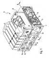
- valve device 6 is designed as a valve battery, which contains a one-piece or, according to the example, modular fluid distributor 7, which is equipped with a plurality of electrically actuated control valves 8.
- control valves 8 are seated in the drawing of them covered mounting surfaces, which open out in the fluid distributor 2 extending channels, which are connected to the valve channels of the control valves 3 in a conventional manner.
- the channels extending in the fluid manifold 7 include a longitudinal manifold feed passage 12 and two parallel first and second manifold vent passages 13, 14. These passages 12, 13, 14 are in fluid communication with each of the control valves 8.
- first and second distributor working channel 15, 16, to the consumer, not shown, can be connected, for example, to be actuated pressure medium drives.
- the fluid loading of the distributor working channels 15, 16 is determined by the control valves 8, which are electrically actuated via an only schematically indicated, running in the fluid distributor 7 electrical signal transmission means 17.
- the fluid distributor 7 is also equipped with a soft start valve 21. Its preferred structure is well visible especially from Figures 3 to 5. It may, for example, be attached to a mounting surface 18 except for the fluid distributor 7, preferably releasably. However, an immediate integration in the fluid distributor 7 would also be possible.
- a first and second distributor supply channel 22, 23 are present, which, however, can also be used as distributor working channels when a control valve 8 is installed on the assembly surface 18 instead of the soft start valve 21.
- a first and second distributor supply channel 22, 23 are present, which, however, can also be used as distributor working channels when a control valve 8 is installed on the assembly surface 18 instead of the soft start valve 21.
- this requires comparable interface dimensions of the control valves 8 and the soft start valve 21 or the interposition of an adapter.
- the distributor feed channel 12 is not supplied with pressure medium in a conventional manner directly via a connection opening from an outer surface of the fluid distributor 7, but via the soft start valve 21.
- the pressure medium in particular compressed air, at the same time via the two manifold supply channels 22, 23 fed and comes from a pressure source, not shown, the two channels 22, 23 provides a pressure medium under a primary pressure available.
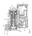
- Soft-start valve 21 includes a valve housing 24 having therein designated in its entirety by reference numeral 25 Main valve means.
- the main valve means 25 are activated by an electrically actuated pilot valve 26, which is installed on or in the valve housing 24 and which can be supplied via an electrical interface 27 with the required electrical actuation signals. Deviating from the embodiment provided for, independent of the electrical signal transmission device 17 electrical supply of the pilot valve 26, this may also be connected to the electrical signal transmission device 17 in a modified embodiment.
- valve housing 24 In the interior of the valve housing 24 is a slide receptacle 28 with a therein in the direction of its longitudinal axis 32 slidable spool 33.
- the spool 33 has a special design, which is better expressed by the fact that he in the FIGS. 3 to 5 is shown cut in different sectional planes.
- the slider receptacle 28 is divided into a plurality of axially successive sections belonging to channels, which thus on the Open outside surface of the valve housing 24 that they communicate with the correct allocation with the provided on the mounting surface openings of the distribution channels.
- a secondary channel 1 communicating with the distribution feeder channel 12, around a soft start channel 2 communicating with the first distribution feeder channel 22, around a bleed channel 3 communicating with the first header ventilation channel 13, and around one with the second distributor channel.
- Supply channel 23 communicating primary channel 4.
- Another duct 5 communicates with the second manifold vent 14, but is inoperative. He could also be omitted.
- the primary pressure fed into the second distributor supply channel 23 remains constant at the same level also in the primary channel 4 of the soft start valve 21.
- the pressure prevailing in the soft start channel 2 is variable and is influenced by throttle means 35, which are expediently installed in the course of the first distributor supply channel 22 in the fluid distributor 7. They are in FIG. 2 merely schematically illustrated, wherein it should be mentioned that the throttle means 35 are preferably designed to be adjustable so that the throttling intensity caused by them can be set variably.
- the throttle means 35 By means of the throttle means 35, the pressure medium flowing in via the first distributor supply channel 22 is lowered from the original primary pressure to a lower soft start pressure, in conjunction with a reduced flow rate.
- the throttle means could also be installed directly in the soft start valve 21. Furthermore, it would be possible to provide a separate throttle device which is connected upstream of the first distributor supply channel 22 or which is placed between the soft start valve 21 and the fluid distributor 7.
- the single control slide 33 of the main valve means 25 is position-dependent able to control the connection of the secondary channel 1 with both the soft start channel 2 and the primary channel 4 and preferably also with the vent channel 3. This allows a relatively simple and at the same time compact design of the Soft-start valve 21. The essential details of this will be described below with particular reference to FIGS FIGS. 3 to 5 explained.
- the overall elongated control slide 33 preferably has a cylindrical outer contour, which is graduated in the longitudinal direction, and protrudes with an end-side end section 36 into a pilot control chamber 37 formed in the interior of the valve housing 24. This is acted upon by the associated pilot valve 26 in a conventional manner with under a pilot pressure stationary control pressure medium or vented to the atmosphere.
- An opening into the pilot chamber 37 pilot control channel 38, which is dominated by the particular designed as a solenoid valve, electrically actuated pilot valve 26 is shown dotted in the drawing. It communicates on the inlet side with a distributor pilot passage 42 extending in the fluid distributor 7 or also directly inside the soft start valve 21 with the primary passage 4.
- the prevailing in the pilot chamber 37 pressure acts on the associated end face 43 of the spool 33 and at the same time the bottom surface 44 of an elongated cavity 45 of the spool 33 in the direction of the longitudinal axis of the spool 33 slidably guided and preferably piston-shaped valve member 46th
- the spool 37 is at least partially tubular, wherein the cavity 45 is open towards the end face 43 and the bottom surface 44 points in the direction of the end face 43.
- the valve member 46 is thus constantly exposed to the pressure prevailing in the pilot chamber 37 pressure.
- An arranged on the outer circumference of the valve member 46 annular seal 47 prevents a flow past pressure medium between the valve member 46 and the wall of the spool 33rd
- the valve member 46 is within the cavity 45 between a FIG. 3 resulting open position and one out FIGS. 4 and 5 resulting closed position in the direction of the longitudinal axis 32 relative to the spool 33 slidably. In the closed position, it assumes a position farther from the end face 43, which position is predetermined in that it comes into abutment against a preferably annular stop 48 situated in the cavity 45.
- the open position is defined by a further stop 52, which lies axially opposite the bottom surface 44 and is formed, for example, by a sleeve inserted into the cavity 45 at the end face.
- the valve member 46 is expediently a seat valve member.
- the annular stop 48 in this case forms a with the bottom surface 44 opposite end face of the valve member 46 cooperating annular valve seat 48a, through which the cavity 45 is divided into a lying axially on this and beyond the valve seat 48a cavity portion 45a, 45b.
- the connection between the two cavity sections 45a, 45b is open or closed.
- the two cavity sections 45a, 45b form the passage sections of a transfer passage 53 extending in the spool valve 33, which opens with at least one inlet opening 54 and at least one outlet opening 55 at axially spaced locations to the peripheral outer surface of the spool valve 33.
- the outlet opening 55 is located on the valve member 46 facing side of the valve seat 48a, the inlet opening 54 beyond the valve seat 48a.
- end-side end portion 36 opposite second end-side end portion 56 of the spool 33 is provided with an axially opposite to the end face 43 oriented actuating surface 57. It is expediently ring-shaped and can be formed in particular directly on the spool 33.
- the actuating surface 57 is located on a piston-like actuating portion 58 which is slidably mounted under sealing means 62 caused peripheral seal in a valve housing 24, preferably cylindrical piston receptacle 63.
- the actuating surface 57 axially opposite and therefore upstream of the second end-side end portion 56 of the spool 33 is disposed in the piston seat 63 with respect to the spool 33 a separate stop piston 64. He is also sealed by sealing means 65 to the peripheral wall of the piston seat 63, so that it defines a sealed operating space 66 together with the actuating portion 58.
- the stop piston 64 is displaceable both with respect to the spool 33 and with respect to the valve housing 24 in the axial direction of the spool 33. In the relative movement between the stop piston 46 and the spool 33, the volume of the enclosed operating space 66 changes.
- the operating space 66 and thus the actuating surface 57 can be acted upon and in particular constantly acted upon by the soft start pressure currently prevailing in the soft start channel during operation of the valve device 6.
- This is done via an in FIG. 4 by a dotted line clarified control channel 67, which extends in sections in the spool 33 and opens at least one control pressure tap opening 68 to the outer peripheral surface of the spool 33.
- the control pressure working opening 68 is simultaneously formed by the outlet opening 55. In any case, it is so positioned on the spool 33 that it is in still to be explained switching positions of the spool 33 with the soft start channel 2 or the secondary channel 1 in conjunction. In this way, the same pressure prevails in the operating chamber 66 as in the soft-start channel 2 or in the secondary channel 1.
- stop means 72, 73 By stop means 72, 73, the relative extension movement between the spool 33 and the stopper piston 46 is limited stroke. If the two components move axially away from one another, the stop means 72, 73 which are arranged on the stop piston 46 and on the control slide 33 meet after a certain relative distance and prevent a further relative movement in the sense of an axial removal.
- the piston-side stop means 72 are in the embodiment at the end-side end portion of a preferably cylindrical piston extension 74 of the stop piston 64, which projects to the spool 33 and dipped into a control chamber 66 open towards Steuerschieberaus strictlyung 75 slidably guided.
- the control slide-side stop means 73 are exemplified by the end face of a inserted into the SteuerschieberausEnglishung 75 and in particular pressed stop sleeve 76 is formed, which is an integral part of the spool 33 and the embodiment also carries the operating portion 58.
- the spool 33 in a FIG. 3 be shown in the clear ventilation position. He takes it as far as possible in the direction of the pilot chamber 37 displaced position.
- the venting position is predefined, for example, by the fact that the spool valve 33, with its end face 43 assigned to the pilot control chamber 37, comes into abutment against a valve housing-fixed end wall 78 axially delimiting the pilot control chamber 37.
- the urging means 77 are capable of exerting an urging force 79 indicated by an arrow on the spool valve 33. However, this does not happen directly, but indirectly with the interposition of the stop piston 64. On this act the biasing means 77, which transmits the biasing force 79 by axial contact with the spool 33 on this.
- stop piston 64 and spool 33 take the widest possible approach to one another position.
- the stop piston 64 may in this case rest in particular directly on the actuating surface 57.
- the piston extension 74 is immersed as far as possible in the spool recess 75.
- the power transmission between the stop piston 64 and the spool 33 also take place in that the piston extension 74 rests against the end face of the axially facing base surface of the Steuerschieberaus Principleung 75.
- the biasing means 77 consist in the advantageous embodiment of a pressing spring means 82. It pushes the stopper piston 64 and consequently the spool 33 constantly in the direction of the venting position. Preferably, it dips through the stop piston 64 into the hollow piston extension 74 in order to support itself at one end against the bottom wall 84 and at the other end against a second end wall 83 of the valve housing.
- the second end wall 83 is opposite to the stop piston 64 on the axial side opposite the operating section 58 and thus delimits a loading space 85 receiving the loading means 77.
- the spring means 82 and the biasing means 77 include a in FIG. 3 only schematically dash-dotted lines indicated second pilot valve 26 a, which is able to act on the loading space 85 controlled with pressure medium.
- the fed pressure medium then acts comparable to the spring device 82 on the stop piston 64 and thus shifts the spool 33 in the venting position. In this case, a pressure pulse is sufficient if at the same time the opposite pilot chamber 37 is vented.
- the secondary channel 1 In the venting position of the spool 33, the secondary channel 1 can be vented through the transfer passage 53 to the vent passage 33 and thus to the atmosphere. As a result, the secondary channel 1 is depressurized and in the exemplary embodiment of the distributor feed channel 12 connected thereto. In this way, the entire valve device 6 can be depressurized.
- the vent flow is in FIG. 3 indicated by a dashed line. It is obvious that to ensure the venting function of the transfer channel 53 is arranged so that in the Vent position, the inlet opening 54 communicates with the secondary channel 1 and the outlet opening 55 with the vent channel 3.
- valve member 46 assumes the open position. Since the pilot chamber 37 is vented, the secondary pressure is able to move the valve member 46 and lift off the valve seat 48 a.
- both the soft start channel 2 and the primary channel 4 are shut off by an interaction of the spool 33 with the sealing means 34.
- the pilot pressure is applied by actuation of the pilot valve 26 in the pilot chamber 37. This acts on the spool 33 and displaces it in the direction of the second, end wall 83.
- the effective pressurization surface consists here of the end face 43 of the spool 33 and the bottom surface 44 of the valve member 46 together. The latter is because the pilot pressure shifts the valve member 46 until it rests against the stop 48 or valve seat 48a, thereby introducing the pressure force acting on the valve member 46 into the control slide 33. This condition is clearly visible FIG. 4 ,
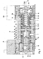
- This soft start position is further characterized in that the control slide 33 has established a fluidic connection between the soft start channel 2 and the secondary channel 1.
- pressure medium flows according to the in FIG. 4 dashed line from the soft start channel 2 in the secondary channel 1 via and from the latter example in the distribution feed channel 12 of the valve device. 6
- Another feature of the soft start position is that the spool 33 occupies a closed position with respect to the connection between the secondary channel 1 and primary channel 4. The secondary channel 1 is thus shut off from the primary channel 4. A shut-off of pressure medium between the soft-start channel 2 and the primary channel 4 through the transfer channel 53 is prevented by the valve member 46 held in the closed position due to its fluid loading.
- the soft start pressure in the soft start position and the operating space 66 is supplied, which in FIG. 4 indicated by a dashed line.
- the pressure tap on the positioned in the soft start channel 2 control pressure tap opening 68 is conceivable that this comes to lie in the Softstar too in the region of the secondary channel 1.
- the position is irrelevant because in the soft start channel 2 and in the secondary channel 1 in the soft start position practically the same pressure prevails:
- the operating pressure prevailing in the operating chamber 66 also increases.
- a predetermined level of the operating pressure of the spool 33 switches off in the FIG. 5 apparent working position. This is done against the still existing biasing force 86, with which the spool 33 is acted upon by the located in the pilot chamber 37 control pressure medium.
- the switching to the working position ultimately causing pressure level of the secondary channel 1 can be specified on the area ratios between on the one hand the actuating surface 57 and on the other hand, the end face 43 and the bottom surface 44 and also on the also acting on the biasing force 86 pilot pressure.
- the switching threshold may be at a soft start pressure that is half the primary pressure. However, it is completely free when setting the responsible for switching Softstarttikes.
- the working position of the spool 33 is located axially between the venting position and the soft start position. It is predetermined by the co-operating stop means 72, 73.
- the stop piston 46 - By the pressure building up in the operating chamber 66, the stop piston 46 - compared to the soft start position unchanged - held in a stop position in which it is supported on the second end wall 83 fixed to the housing.
- the actuating portion 58 and with this the entire spool 33 performs a relative movement with respect to the valve housing 24 and the stop piston 64, in which it moves according to arrow 87 in the direction of the venting position, but before reaching this is stopped by the two stop means 72nd , 73 run into each other. This defines the working position.
- the geometry of the spool 33 is selected so that the secondary channel 1 in the working position of the spool 33 according to the in FIG. 5 thinner dashed line also communicates with the soft start channel 2.
- this is not mandatory.
- the working position is maintained as long as in the pilot chamber 37, the pilot pressure is present. If the pilot chamber 37 vented, eliminates the biasing force 86 and the spool 33 is actuated by the biasing means 77 in the already-mentioned venting position FIG. 3 switched back.
- control channel 67 The responsible for the actuation of the actuating surface 57 control channel 67 is connected both in the soft start position and in the working position and during the transition between the two positions with the soft start channel 2 to the required for switching to the working position and maintaining the working position of the pressurization To ensure actuating surface 57.
- a comparison of FIGS. 4 and 5 indicates here that the control pressure tap opening 68 is positioned in each of the aforementioned positions in the region of the soft start channel 2.
- the soft-start valve 21 contains a primary channel 4 charged with a primary pressure, a secondary channel 1 and a soft-start channel 2 acted upon by a throttling means 35 with a soft-start pressure throttled with respect to the primary pressure. Furthermore, it has main valve means 25, by means of which the secondary channel 1 can be connected to the soft-start channel 2 when the primary channel 4 is separated from it and which contains a spool valve 33 which can be positioned in several positions and which counteracts a biasing force 86 from a position separating the primary channel 4 from the secondary channel 1 in a connection releasing the connection between these channels working position can be switched by an actuation surface 57 provided on it from the soft start channel 2 is acted upon by the soft start pressure.
- the spool 33 controls, depending on its position, the connection of the secondary channel 1 with both the primary channel 4 and the soft start channel 2, wherein it is positionable in a soft start channel 2 with the same time separated from the primary channel 4 secondary channel 1 soft start position, from which he on the part of the Soft start pressure occurring admission of the actuating surface 57 can be switched to the working position.
- the soft-start valve 21 integrated into the valve device, a controlled supply and venting of the valve device 6 is possible without recourse to external components. Since the control of the switch positions is caused directly by the pressurization, no electrical pressure sensors are needed.
- the switching function of the soft-start valve 21 can be time-dependent and / or pressure-dependent.
Landscapes
- Engineering & Computer Science (AREA)
- General Engineering & Computer Science (AREA)
- Mechanical Engineering (AREA)
- Physics & Mathematics (AREA)
- Fluid Mechanics (AREA)
- Fluid-Driven Valves (AREA)
- Multiple-Way Valves (AREA)
- Details Of Valves (AREA)
Claims (19)
- Ensemble distributeur à fonction de mise en pression progressive, équipé d'une soupape à mise en pression progressive (21) pourvue d'éléments de distribution principale (25) aptes soit à interrompre la liaison entre un canal primaire (4) soumis à une pression primaire et un canal secondaire (1) dans une position de fermeture précontrainte par un effort de précontrainte (86), soit à établir celle-ci dans une position d'ouverture, les éléments de distribution principale (25) pouvant être soumis à une pression progressive pour commutation en position d'ouverture et la soupape à mise en pression progressive (21) étant en outre apte, lorsque le canal primaire (4) est séparé, à relier le canal secondaire (1) à un canal de mise en pression progressive (2) soumis ou pouvant être soumis à une pression progressive au moins initialement plus faible que la pression primaire du fait de moyens d'étranglement (35), et les éléments de distribution principale (25) contenant un tiroir de commande (33) pouvant être placé dans différentes positions et apte à commander la liaison du canal secondaire (1) tant avec le canal de mise en pression progressive (2) qu'avec le canal primaire (4), caractérisé en ce que le tiroir de commande (33) est solidaire en mouvement avec une surface d'actionnement (57) pouvant être soumise à la pression progressive dans le sens contraire à l'effort de précontrainte (86) qui s'exerce également sur lui, et en ce que le tiroir de commande (33) peut être placé dans une position de purge d'air, où il relie le canal secondaire (1) à un canal de purge d'air (3) communiquant avec l'atmosphère, en cas de séparation simultanée d'avec le canal primaire (4) et le canal de mise en pression progressive (2).
- Ensemble distributeur selon la revendication 1, caractérisé en ce que le tiroir de commande (33) peut être placé dans une position de mise en pression progressive, où il relie le canal de mise en pression progressive (2) au canal secondaire (19) simultanément séparé du canal primaire (4).
- Ensemble distributeur selon l'une des revendications 1 ou 2, caractérisé en ce que le tiroir de commande (33) peut être placé dans une position de travail, où il relie le canal secondaire (1) au canal primaire (4).
- Ensemble distributeur selon la revendication 3, caractérisé en ce que, dans sa position de travail, le tiroir de commande (33) relie le canal secondaire (1) tant au canal primaire (4) qu'au canal de mise en pression progressive (2).
- Ensemble distributeur selon l'un des revendications 1 à 4, caractérisé en ce que la liaison existant en position de purge d'air entre le canal secondaire (1) et le canal de purge d'air (3) est réalisée par un canal de passage (53) traversant le tiroir de commande (33).
- Ensemble distributeur selon la revendication 5, caractérisé en ce qu'au canal de passage (53) est affecté un organe de soupape (46) disposé dans le tiroir de commande (33) et apte à ouvrir le canal de passage (53) dans la position de purge d'air du tiroir de commande (33) et à le fermer dans les autres positions du tiroir de commande (33).
- Ensemble distributeur selon la revendication 6, caractérisé en ce que l'organe de soupape (46) est réalisé en forme de piston et constamment soumis à la pression régnant dans un compartiment pilote (37) où peut être appliquée une pression pilote pour la commutation du tiroir de commande (33) et peut être serré par la pression pilote contre une butée (48) disposée sur le tiroir de commande (33) et notamment formée par un siège de soupape (48a), pour exercer ainsi un effort de réglage sur le tiroir de commande (33).
- Ensemble distributeur selon l'une des revendications 1 à 7, caractérisé par un distributeur de fluide (7) pourvu de plusieurs soupapes pilotes (8), qui comprend un canal d'alimentation du distributeur (12) et au moins un canal de purge d'air du distributeur (13), lesquels sont respectivement reliés aux soupapes pilotes (8), et qui est équipé de la soupape à mise en pression progressive (21), le canal d'alimentation du distributeur (12) étant relié au canal secondaire (1), et le canal primaire (4) et le canal de mise en pression progressive (2) respectivement à un canal d'approvisionnement du distributeur (22, 23) débouchant sur la surface extérieure du distributeur de fluide (7).
- Ensemble distributeur selon la revendication 8, caractérisé en ce que le canal de purge d'air (3) de la soupape à mise en pression progressive (21) est relié à un canal de purge d'air du distributeur (13).
- Ensemble distributeur selon la revendication 8 ou la revendication 9, caractérisé en ce que le distributeur de fluide (7) dispose d'une pluralité de surfaces d'équipement, desquelles partent deux canaux de travail du distributeur (15, 16) traversant le distributeur de fluide (7) et qui sont fonctionnellement au moins partiellement équipables en option d'une soupape pilote (8) ou d'une soupape à mise en pression progressive (21), les canaux de travail du distributeur (15, 16) étant utilisables comme canaux d'approvisionnement du distributeur (22, 23) en cas d'équipement de la surface d'équipement correspondante avec une soupape à mise en pression progressive (21).
- Ensemble distributeur selon l'une des revendications 8 à 10, caractérisé en ce qu'au canal d'approvisionnement du distributeur (22) communiquant avec le canal de mise en pression progressive (2) sont affectés des moyens d'étranglement (35) montés sur son parcours, ou montés en amont ou en aval de celui-ci.
- Ensemble distributeur selon l'une des revendications 1 à 11, caractérisé en ce que l'intensité d'étranglement des moyens d'étranglement (35) est réglable.
- Ensemble distributeur selon l'une des revendications 1 à 12, caractérisé en ce que la surface d'actionnement (57) du tiroir de commande (33) délimite un espace d'actionnement (66) pouvant être soumis à la pression progressive.
- Ensemble distributeur selon la revendication 13, caractérisé en ce que l'espace d'actionnement (66) est relié au canal de mise en pression progressive (2) et/ou au canal secondaire (1) par au moins un canal de commande (67), au moins lorsque le tiroir de commande (33) occupe sa position de mise en pression progressive reliant le canal de mise en pression progressive (2) au canal secondaire (1).
- Ensemble distributeur selon la revendication 13 ou la revendication 14, caractérisé en ce que le canal de commande (67) s'étend au moins partiellement dans le tiroir de commande (33) et débouche fonctionnellement par au moins une ouverture de saisie de pression de commande (68) à un emplacement sur la périphérie extérieure du tiroir de commande (33), de telle manière que ladite ouverture de saisie de pression de commande (68) communique avec le canal de mise en pression progressive (2) ou le canal secondaire (1) tant en position de mise en pression progressive reliant le canal secondaire (1) au canal de mise en pression progressive (2) qu'en position de travail reliant le canal secondaire (1) au canal primaire (4).
- Ensemble distributeur selon l'une des revendications 13 à 15, caractérisé en ce que l'espace d'actionnement (66) est délimité sur le côté opposé à la surface d'actionnement (57) par un piston de butée (46) réglable en direction axiale du tiroir de commande (33) tant par rapport au tiroir de commande (33) qu'au carter de soupape (24), et réglable, par le tiroir de commande (33) se déplaçant vers la position de mise en pression progressive, dans une position de butée à appui fixe sur le carter qui définit simultanément la position de mise en pression progressive du tiroir de commande (33), ledit piston de butée coopérant avec le tiroir de commande (33) par des éléments de butée (72, 73) de manière à arrêter le mouvement de commutation de celui-ci consécutif à une élévation de pression dans l'espace d'actionnement (66) une fois la position de travail atteinte.
- Ensemble distributeur selon la revendication 16, caractérisé en ce que le piston de butée (64) est précontraint ou peut être précontraint par des moyens de contrainte (77) dans la direction du tiroir de commande (33), lesdits moyens de contrainte (77) étant formés par un dispositif à ressort (82) s'appuyant contre le carter de soupape (24) et qui est comprimé lorsque le piston de butée (64) est déplacé en position de butée.
- Ensemble distributeur selon la revendication 16 ou la revendication 17, caractérisé en ce qu'une extension de piston (74) à plongée coaxiale dans le tiroir de commande (33), à laquelle les éléments de butée (72, 73) sont fonctionnellement affectés, est disposée contre le piston de butée (64).
- Ensemble distributeur selon l'une des revendications 1 à 18, caractérisé en ce que le tiroir de commande (33) plonge par une section d'extrémité frontale (36) dans un compartiment pilote (37) pouvant être soumis à une pression pilote pour générer l'effort de précontrainte (86), ledit compartiment pilote (37) étant fonctionnellement affecté à la section d'extrémité frontale (36) du tiroir de commande (33) opposée à la surface d'actionnement (57).
Applications Claiming Priority (2)
| Application Number | Priority Date | Filing Date | Title |
|---|---|---|---|
| DE102006010845A DE102006010845B4 (de) | 2006-03-09 | 2006-03-09 | Ventileinrichtung mit Softstartfunktion |
| PCT/EP2007/000570 WO2007101503A1 (fr) | 2006-03-09 | 2007-01-24 | Ensemble distributeur à fonction de mise en pression progressive |
Publications (2)
| Publication Number | Publication Date |
|---|---|
| EP1991790A1 EP1991790A1 (fr) | 2008-11-19 |
| EP1991790B1 true EP1991790B1 (fr) | 2010-04-28 |
Family
ID=37965119
Family Applications (1)
| Application Number | Title | Priority Date | Filing Date |
|---|---|---|---|
| EP07702979A Not-in-force EP1991790B1 (fr) | 2006-03-09 | 2007-01-24 | Ensemble distributeur à fonction de mise en pression progressive |
Country Status (5)
| Country | Link |
|---|---|
| EP (1) | EP1991790B1 (fr) |
| CN (1) | CN101400899B (fr) |
| AT (1) | ATE466198T1 (fr) |
| DE (2) | DE102006010845B4 (fr) |
| WO (1) | WO2007101503A1 (fr) |
Families Citing this family (3)
| Publication number | Priority date | Publication date | Assignee | Title |
|---|---|---|---|---|
| DE202009007194U1 (de) * | 2009-05-19 | 2010-11-04 | Bürkert Werke GmbH | Analysesystem |
| CN101761682B (zh) * | 2010-02-09 | 2011-11-30 | 费斯托(中国)有限公司 | 软启动阀 |
| DE102015001539B4 (de) * | 2015-02-06 | 2022-03-17 | Festo Se & Co. Kg | Ventilbatterie |
Family Cites Families (8)
| Publication number | Priority date | Publication date | Assignee | Title |
|---|---|---|---|---|
| US3256906A (en) * | 1963-02-05 | 1966-06-21 | Walter D Ludwig | Bi-directional time delay valve |
| US3269416A (en) * | 1964-05-25 | 1966-08-30 | American Brake Shoe Co | Control valve mechanism with means for reducing hydraulic shock |
| DE3509183C1 (de) * | 1985-03-14 | 1986-07-03 | Georg Rost & Söhne Armaturenfabrik GmbH & Co KG, 4952 Porta Westfalica | Selbstschlussarmatur |
| DE3815939A1 (de) * | 1988-05-10 | 1989-11-23 | Bayerische Motoren Werke Ag | Steuervorrichtung fuer pneumatische systeme, insbesondere pneumatik-zylinder an arbeits- und fertigungs-maschinen oder -anlagen |
| US5038813A (en) * | 1990-05-21 | 1991-08-13 | Rossow David E | Pneumatic starter device |
| DE9105458U1 (de) * | 1991-04-29 | 1991-06-13 | Mannesmann AG, 4000 Düsseldorf | Ventileinheit zum gedämpften Schalten eines Hauptdruckmittelweges |
| US5699829A (en) * | 1996-05-14 | 1997-12-23 | Ross Operating Vale Co. | Fluid control valve with soft startup |
| DE202004015468U1 (de) * | 2004-10-06 | 2005-01-05 | Festo Ag & Co.Kg | Softstartvorrichtung für Druckluftsysteme |
-
2006
- 2006-03-09 DE DE102006010845A patent/DE102006010845B4/de not_active Expired - Fee Related
-
2007
- 2007-01-24 EP EP07702979A patent/EP1991790B1/fr not_active Not-in-force
- 2007-01-24 AT AT07702979T patent/ATE466198T1/de active
- 2007-01-24 CN CN200780008523.9A patent/CN101400899B/zh not_active Expired - Fee Related
- 2007-01-24 DE DE502007003593T patent/DE502007003593D1/de active Active
- 2007-01-24 WO PCT/EP2007/000570 patent/WO2007101503A1/fr not_active Ceased
Also Published As
| Publication number | Publication date |
|---|---|
| ATE466198T1 (de) | 2010-05-15 |
| EP1991790A1 (fr) | 2008-11-19 |
| DE502007003593D1 (de) | 2010-06-10 |
| WO2007101503A1 (fr) | 2007-09-13 |
| DE102006010845B4 (de) | 2009-04-30 |
| CN101400899B (zh) | 2012-12-12 |
| CN101400899A (zh) | 2009-04-01 |
| DE102006010845A1 (de) | 2007-09-13 |
Similar Documents
| Publication | Publication Date | Title |
|---|---|---|
| DE102013016652B4 (de) | Ventilbatterie mit Sicherheitsventil | |
| EP1860328A1 (fr) | Dispositif de contrôle de vérin pneumatique à double effet | |
| EP2397732A2 (fr) | Dispositif d'entraînement d'une soupape à double siège | |
| EP3481687A1 (fr) | Soupape de relâchement de frein de stationnement pour un véhicule tracté | |
| DE3529802A1 (de) | Zweihand-sicherheitssteuerung | |
| EP2577122B1 (fr) | Soupape à voies multiples et méthode pour l'actionner | |
| EP1788257B1 (fr) | Vérin avec verrouillage de fin de course | |
| EP1991790B1 (fr) | Ensemble distributeur à fonction de mise en pression progressive | |
| EP2251552A1 (fr) | Soupape | |
| EP2426388B1 (fr) | Soupape à plusieurs voies précommandée | |
| EP2061982B1 (fr) | Dispositif de production d'un vide | |
| EP0838744A1 (fr) | Régulateur de pression équipé d'une fonction d'interruption | |
| EP0600178B1 (fr) | Valve de commande pour remorques | |
| EP2047109B1 (fr) | Ensemble distributeur à fonction de mise en pression progressive | |
| EP2047108B1 (fr) | Ensemble de soupape à ouverture en fondu (soft start) | |
| DE3871680T2 (de) | Ventileinheit, insbesondere zur verwendung im pneumatischen bremssystem eines zugfahrzeugs zur steuerung der bremsen eines anhaengers. | |
| DE102012007170B3 (de) | Antriebsvorrichtung | |
| DE29818762U1 (de) | Fluidbetätigte Arbeitsvorrichtung | |
| DE10161703B4 (de) | Entlüftungseinrichtung für einen Pneumatikantrieb | |
| DE102016213820B3 (de) | Ventil | |
| DE69328075T2 (de) | Steuerventil für eine hydraulische Bremsanlage | |
| EP2092226B1 (fr) | Distributeur à plusieurs voies | |
| DE3639149A1 (de) | Lastabhaengig steuerbare bremskraftregeleinrichtung | |
| DE29712709U1 (de) | Mehrwegeventil | |
| DE102016223685A1 (de) | Ventilanordnung |
Legal Events
| Date | Code | Title | Description |
|---|---|---|---|
| PUAI | Public reference made under article 153(3) epc to a published international application that has entered the european phase |
Free format text: ORIGINAL CODE: 0009012 |
|
| 17P | Request for examination filed |
Effective date: 20080711 |
|
| AK | Designated contracting states |
Kind code of ref document: A1 Designated state(s): AT BE BG CH CY CZ DE DK EE ES FI FR GB GR HU IE IS IT LI LT LU LV MC NL PL PT RO SE SI SK TR |
|
| 17Q | First examination report despatched |
Effective date: 20090127 |
|
| GRAP | Despatch of communication of intention to grant a patent |
Free format text: ORIGINAL CODE: EPIDOSNIGR1 |
|
| DAX | Request for extension of the european patent (deleted) | ||
| GRAS | Grant fee paid |
Free format text: ORIGINAL CODE: EPIDOSNIGR3 |
|
| GRAA | (expected) grant |
Free format text: ORIGINAL CODE: 0009210 |
|
| AK | Designated contracting states |
Kind code of ref document: B1 Designated state(s): AT BE BG CH CY CZ DE DK EE ES FI FR GB GR HU IE IS IT LI LT LU LV MC NL PL PT RO SE SI SK TR |
|
| REG | Reference to a national code |
Ref country code: GB Ref legal event code: FG4D Free format text: NOT ENGLISH |
|
| REG | Reference to a national code |
Ref country code: CH Ref legal event code: EP |
|
| REG | Reference to a national code |
Ref country code: IE Ref legal event code: FG4D Free format text: LANGUAGE OF EP DOCUMENT: GERMAN |
|
| REF | Corresponds to: |
Ref document number: 502007003593 Country of ref document: DE Date of ref document: 20100610 Kind code of ref document: P |
|
| REG | Reference to a national code |
Ref country code: NL Ref legal event code: VDEP Effective date: 20100428 |
|
| LTIE | Lt: invalidation of european patent or patent extension |
Effective date: 20100428 |
|
| PG25 | Lapsed in a contracting state [announced via postgrant information from national office to epo] |
Ref country code: NL Free format text: LAPSE BECAUSE OF FAILURE TO SUBMIT A TRANSLATION OF THE DESCRIPTION OR TO PAY THE FEE WITHIN THE PRESCRIBED TIME-LIMIT Effective date: 20100428 Ref country code: LT Free format text: LAPSE BECAUSE OF FAILURE TO SUBMIT A TRANSLATION OF THE DESCRIPTION OR TO PAY THE FEE WITHIN THE PRESCRIBED TIME-LIMIT Effective date: 20100428 Ref country code: ES Free format text: LAPSE BECAUSE OF FAILURE TO SUBMIT A TRANSLATION OF THE DESCRIPTION OR TO PAY THE FEE WITHIN THE PRESCRIBED TIME-LIMIT Effective date: 20100808 Ref country code: SE Free format text: LAPSE BECAUSE OF FAILURE TO SUBMIT A TRANSLATION OF THE DESCRIPTION OR TO PAY THE FEE WITHIN THE PRESCRIBED TIME-LIMIT Effective date: 20100428 |
|
| REG | Reference to a national code |
Ref country code: IE Ref legal event code: FD4D |
|
| PG25 | Lapsed in a contracting state [announced via postgrant information from national office to epo] |
Ref country code: SI Free format text: LAPSE BECAUSE OF FAILURE TO SUBMIT A TRANSLATION OF THE DESCRIPTION OR TO PAY THE FEE WITHIN THE PRESCRIBED TIME-LIMIT Effective date: 20100428 Ref country code: FI Free format text: LAPSE BECAUSE OF FAILURE TO SUBMIT A TRANSLATION OF THE DESCRIPTION OR TO PAY THE FEE WITHIN THE PRESCRIBED TIME-LIMIT Effective date: 20100428 Ref country code: IS Free format text: LAPSE BECAUSE OF FAILURE TO SUBMIT A TRANSLATION OF THE DESCRIPTION OR TO PAY THE FEE WITHIN THE PRESCRIBED TIME-LIMIT Effective date: 20100828 Ref country code: LV Free format text: LAPSE BECAUSE OF FAILURE TO SUBMIT A TRANSLATION OF THE DESCRIPTION OR TO PAY THE FEE WITHIN THE PRESCRIBED TIME-LIMIT Effective date: 20100428 |
|
| PG25 | Lapsed in a contracting state [announced via postgrant information from national office to epo] |
Ref country code: CY Free format text: LAPSE BECAUSE OF FAILURE TO SUBMIT A TRANSLATION OF THE DESCRIPTION OR TO PAY THE FEE WITHIN THE PRESCRIBED TIME-LIMIT Effective date: 20100602 Ref country code: PL Free format text: LAPSE BECAUSE OF FAILURE TO SUBMIT A TRANSLATION OF THE DESCRIPTION OR TO PAY THE FEE WITHIN THE PRESCRIBED TIME-LIMIT Effective date: 20100428 |
|
| PG25 | Lapsed in a contracting state [announced via postgrant information from national office to epo] |
Ref country code: EE Free format text: LAPSE BECAUSE OF FAILURE TO SUBMIT A TRANSLATION OF THE DESCRIPTION OR TO PAY THE FEE WITHIN THE PRESCRIBED TIME-LIMIT Effective date: 20100428 Ref country code: PT Free format text: LAPSE BECAUSE OF FAILURE TO SUBMIT A TRANSLATION OF THE DESCRIPTION OR TO PAY THE FEE WITHIN THE PRESCRIBED TIME-LIMIT Effective date: 20100830 Ref country code: DK Free format text: LAPSE BECAUSE OF FAILURE TO SUBMIT A TRANSLATION OF THE DESCRIPTION OR TO PAY THE FEE WITHIN THE PRESCRIBED TIME-LIMIT Effective date: 20100428 Ref country code: IE Free format text: LAPSE BECAUSE OF FAILURE TO SUBMIT A TRANSLATION OF THE DESCRIPTION OR TO PAY THE FEE WITHIN THE PRESCRIBED TIME-LIMIT Effective date: 20100428 |
|
| PG25 | Lapsed in a contracting state [announced via postgrant information from national office to epo] |
Ref country code: SK Free format text: LAPSE BECAUSE OF FAILURE TO SUBMIT A TRANSLATION OF THE DESCRIPTION OR TO PAY THE FEE WITHIN THE PRESCRIBED TIME-LIMIT Effective date: 20100428 Ref country code: RO Free format text: LAPSE BECAUSE OF FAILURE TO SUBMIT A TRANSLATION OF THE DESCRIPTION OR TO PAY THE FEE WITHIN THE PRESCRIBED TIME-LIMIT Effective date: 20100428 Ref country code: CZ Free format text: LAPSE BECAUSE OF FAILURE TO SUBMIT A TRANSLATION OF THE DESCRIPTION OR TO PAY THE FEE WITHIN THE PRESCRIBED TIME-LIMIT Effective date: 20100428 |
|
| PLBE | No opposition filed within time limit |
Free format text: ORIGINAL CODE: 0009261 |
|
| STAA | Information on the status of an ep patent application or granted ep patent |
Free format text: STATUS: NO OPPOSITION FILED WITHIN TIME LIMIT |
|
| 26N | No opposition filed |
Effective date: 20110131 |
|
| PG25 | Lapsed in a contracting state [announced via postgrant information from national office to epo] |
Ref country code: GR Free format text: LAPSE BECAUSE OF FAILURE TO SUBMIT A TRANSLATION OF THE DESCRIPTION OR TO PAY THE FEE WITHIN THE PRESCRIBED TIME-LIMIT Effective date: 20100729 |
|
| BERE | Be: lapsed |
Owner name: FESTO A.G. & CO. KG Effective date: 20110131 |
|
| PG25 | Lapsed in a contracting state [announced via postgrant information from national office to epo] |
Ref country code: MC Free format text: LAPSE BECAUSE OF NON-PAYMENT OF DUE FEES Effective date: 20110131 |
|
| REG | Reference to a national code |
Ref country code: CH Ref legal event code: PL |
|
| PG25 | Lapsed in a contracting state [announced via postgrant information from national office to epo] |
Ref country code: LI Free format text: LAPSE BECAUSE OF NON-PAYMENT OF DUE FEES Effective date: 20110131 Ref country code: CH Free format text: LAPSE BECAUSE OF NON-PAYMENT OF DUE FEES Effective date: 20110131 |
|
| PG25 | Lapsed in a contracting state [announced via postgrant information from national office to epo] |
Ref country code: BE Free format text: LAPSE BECAUSE OF NON-PAYMENT OF DUE FEES Effective date: 20110131 |
|
| REG | Reference to a national code |
Ref country code: AT Ref legal event code: MM01 Ref document number: 466198 Country of ref document: AT Kind code of ref document: T Effective date: 20120124 |
|
| PG25 | Lapsed in a contracting state [announced via postgrant information from national office to epo] |
Ref country code: LU Free format text: LAPSE BECAUSE OF NON-PAYMENT OF DUE FEES Effective date: 20110124 |
|
| PG25 | Lapsed in a contracting state [announced via postgrant information from national office to epo] |
Ref country code: AT Free format text: LAPSE BECAUSE OF NON-PAYMENT OF DUE FEES Effective date: 20120124 |
|
| PG25 | Lapsed in a contracting state [announced via postgrant information from national office to epo] |
Ref country code: BG Free format text: LAPSE BECAUSE OF FAILURE TO SUBMIT A TRANSLATION OF THE DESCRIPTION OR TO PAY THE FEE WITHIN THE PRESCRIBED TIME-LIMIT Effective date: 20100728 Ref country code: TR Free format text: LAPSE BECAUSE OF FAILURE TO SUBMIT A TRANSLATION OF THE DESCRIPTION OR TO PAY THE FEE WITHIN THE PRESCRIBED TIME-LIMIT Effective date: 20100428 |
|
| PG25 | Lapsed in a contracting state [announced via postgrant information from national office to epo] |
Ref country code: HU Free format text: LAPSE BECAUSE OF FAILURE TO SUBMIT A TRANSLATION OF THE DESCRIPTION OR TO PAY THE FEE WITHIN THE PRESCRIBED TIME-LIMIT Effective date: 20100428 |
|
| REG | Reference to a national code |
Ref country code: FR Ref legal event code: PLFP Year of fee payment: 10 |
|
| REG | Reference to a national code |
Ref country code: FR Ref legal event code: PLFP Year of fee payment: 11 |
|
| PGFP | Annual fee paid to national office [announced via postgrant information from national office to epo] |
Ref country code: GB Payment date: 20161220 Year of fee payment: 11 |
|
| PGFP | Annual fee paid to national office [announced via postgrant information from national office to epo] |
Ref country code: FR Payment date: 20170124 Year of fee payment: 11 |
|
| PGFP | Annual fee paid to national office [announced via postgrant information from national office to epo] |
Ref country code: IT Payment date: 20170125 Year of fee payment: 11 |
|
| GBPC | Gb: european patent ceased through non-payment of renewal fee |
Effective date: 20180124 |
|
| PG25 | Lapsed in a contracting state [announced via postgrant information from national office to epo] |
Ref country code: FR Free format text: LAPSE BECAUSE OF NON-PAYMENT OF DUE FEES Effective date: 20180131 |
|
| REG | Reference to a national code |
Ref country code: FR Ref legal event code: ST Effective date: 20180928 |
|
| PG25 | Lapsed in a contracting state [announced via postgrant information from national office to epo] |
Ref country code: GB Free format text: LAPSE BECAUSE OF NON-PAYMENT OF DUE FEES Effective date: 20180124 |
|
| PG25 | Lapsed in a contracting state [announced via postgrant information from national office to epo] |
Ref country code: IT Free format text: LAPSE BECAUSE OF NON-PAYMENT OF DUE FEES Effective date: 20180124 |
|
| REG | Reference to a national code |
Ref country code: DE Ref legal event code: R082 Ref document number: 502007003593 Country of ref document: DE Representative=s name: PATENTANWAELTE MAGENBAUER & KOLLEGEN PARTNERSC, DE Ref country code: DE Ref legal event code: R081 Ref document number: 502007003593 Country of ref document: DE Owner name: FESTO SE & CO. KG, DE Free format text: FORMER OWNER: FESTO AG & CO. KG, 73734 ESSLINGEN, DE Ref country code: DE Ref legal event code: R081 Ref document number: 502007003593 Country of ref document: DE Owner name: FESTO AG & CO. KG, DE Free format text: FORMER OWNER: FESTO AG & CO. KG, 73734 ESSLINGEN, DE |
|
| PGFP | Annual fee paid to national office [announced via postgrant information from national office to epo] |
Ref country code: DE Payment date: 20201113 Year of fee payment: 15 |
|
| REG | Reference to a national code |
Ref country code: DE Ref legal event code: R119 Ref document number: 502007003593 Country of ref document: DE |
|
| PG25 | Lapsed in a contracting state [announced via postgrant information from national office to epo] |
Ref country code: DE Free format text: LAPSE BECAUSE OF NON-PAYMENT OF DUE FEES Effective date: 20220802 |