EP1991999B1 - Commutateur électrique - Google Patents
Commutateur électrique Download PDFInfo
- Publication number
- EP1991999B1 EP1991999B1 EP20070704621 EP07704621A EP1991999B1 EP 1991999 B1 EP1991999 B1 EP 1991999B1 EP 20070704621 EP20070704621 EP 20070704621 EP 07704621 A EP07704621 A EP 07704621A EP 1991999 B1 EP1991999 B1 EP 1991999B1
- Authority
- EP
- European Patent Office
- Prior art keywords
- interrupter unit
- air
- switch
- grounding switch
- interrupter
- Prior art date
- Legal status (The legal status is an assumption and is not a legal conclusion. Google has not performed a legal analysis and makes no representation as to the accuracy of the status listed.)
- Ceased
Links
- 238000000034 method Methods 0.000 claims abstract description 12
- 238000002955 isolation Methods 0.000 claims 11
- 239000004020 conductor Substances 0.000 abstract 1
- 238000000926 separation method Methods 0.000 description 21
- 230000000750 progressive effect Effects 0.000 description 4
- 238000010586 diagram Methods 0.000 description 2
- 230000008878 coupling Effects 0.000 description 1
- 238000010168 coupling process Methods 0.000 description 1
- 238000005859 coupling reaction Methods 0.000 description 1
- 230000001419 dependent effect Effects 0.000 description 1
- 238000007599 discharging Methods 0.000 description 1
- 230000001939 inductive effect Effects 0.000 description 1
Images

Classifications
-
- H—ELECTRICITY
- H01—ELECTRIC ELEMENTS
- H01H—ELECTRIC SWITCHES; RELAYS; SELECTORS; EMERGENCY PROTECTIVE DEVICES
- H01H33/00—High-tension or heavy-current switches with arc-extinguishing or arc-preventing means
- H01H33/02—Details
- H01H33/04—Means for extinguishing or preventing arc between current-carrying parts
- H01H33/12—Auxiliary contacts on to which the arc is transferred from the main contacts
- H01H33/121—Load break switches
- H01H33/125—Load break switches comprising a separate circuit breaker
- H01H33/126—Load break switches comprising a separate circuit breaker being operated by the distal end of a sectionalising contact arm
-
- H—ELECTRICITY
- H01—ELECTRIC ELEMENTS
- H01H—ELECTRIC SWITCHES; RELAYS; SELECTORS; EMERGENCY PROTECTIVE DEVICES
- H01H31/00—Air-break switches for high tension without arc-extinguishing or arc-preventing means
- H01H31/003—Earthing switches
-
- H—ELECTRICITY
- H01—ELECTRIC ELEMENTS
- H01H—ELECTRIC SWITCHES; RELAYS; SELECTORS; EMERGENCY PROTECTIVE DEVICES
- H01H33/00—High-tension or heavy-current switches with arc-extinguishing or arc-preventing means
- H01H33/60—Switches wherein the means for extinguishing or preventing the arc do not include separate means for obtaining or increasing flow of arc-extinguishing fluid
- H01H33/66—Vacuum switches
- H01H33/666—Operating arrangements
- H01H33/6661—Combination with other type of switch, e.g. for load break switches
Definitions
- the invention relates to an electrical switching device with a first interrupter unit for interrupting and connecting an electrical line, in particular an air-insulated earthing switch, wherein in the electrical switching device at least a second encapsulated interrupter unit is arranged parallel to the first interrupter unit and the voltage flashovers arising when connecting or disconnecting the electrical line Arcs occur in the second interrupter unit, wherein the second interrupter unit when connecting the electrical line before the first interrupter unit and when interrupting the electrical line after the first interrupter unit is switchable. Furthermore, the invention relates to a method for switching an air-insulated earthing switch, wherein at the air-insulated earthing switch no arc due to a voltage flashover or the contact separation is formed.
- Conventional air-insulated earthing switches are designed as a swivel or as a swing-thruster earth electrode. When connecting a line or a switchgear to the ground potential or switching off the earth potential, these switch-on processes generate a capacitive and / or an inductive current, which can lead to an arc at a certain distance between the main contacts of the earthing switch. Since the earthing switches are usually operated in open-air systems, this open arc poses a risk to the persons and electrical devices in the system. To date, this problem has been solved by switching an auxiliary contact with a leading or lagging function to the main contact. Only at the auxiliary contact ignites an emerging arc. As a result, the main contacts of the air-insulated earthing switch are protected from the action of arcing. The disadvantage here is that the case Arcing continues to develop outdoors and thus poses a safety risk.
- An electrical switching device of the type mentioned is from the US 5,276,286 known.
- the object of the present invention is to ensure arc-free switching of a main switch.
- the object is achieved in that a circuit breaker between the air-insulated earthing switch and the second interrupter unit is arranged and by means of a receiving device on a movable main contact of the air-insulated earthing switch befind Anlagen first part of the circuit breaker makes contact with the second part of the circuit breaker.
- the inventive switchgear ensures that a possible arc occurs exclusively in the second interrupter unit and thus the first interrupter unit can be switched in an arc-free manner.
- this results in the advantage that a possible arc does not occur at the main contacts of the air-insulated earthing switch and thus extends the life of the switchgear.
- the receiving device By the movement of the movable main contact by means of the first part of the circuit breaker, the receiving device performs a rotational movement. Shortly before reaching the end position for the switched state of the main movable contact performs a lifting movement in the fixed main contact. This movement sequence of the movable main contact is used to interrupt the existing electrical connection between the two parts of the circuit breaker again in the on state. Previously, the vacuum switching chamber has been switched by the rotation and lifting movement. In the end position of the movable main contact in the switched state, the second interrupter unit is therefore again electrically separated from the main flow path by the opened disconnect switch.
- the first part of the circuit breaker is dimensioned so that with a sufficient separation distance between the main contacts, the receiving device due to the rotational movement then the second interrupter unit, such as a vacuum interrupter opens. A resulting arc remains in the chamber of the second interrupter unit.
- the circuit breaker can also be opened without power. This movement is ensured by the coordinated geometry and design of the movable main contact, the length and arrangement of the first part of the circuit breaker, as well as the design of the receiving device.
- the second interrupter unit is a circuit breaker and / or a load switch and / or a disconnector and / or a vacuum interrupter chamber and / or a surge arrester, e.g. a spark gap and / or a voltage limiter.
- the arc is ignited exclusively in the closed chamber of the second interrupter unit and thus shielded to the outside.
- a serial arrangement of the two sub-cup units can be used.
- the second interrupter unit is arranged on the voltage potential side, in particular the high-voltage potential side, which is applied to the switching device.
- at least one further interrupter unit for discharging overvoltages is arranged in parallel and / or in series with the second interrupter unit.
- the third interrupter unit is a surge arrester, a spark gap, open or encapsulated or other voltage limiters.
- the rated voltage of the second interrupter unit can be selected smaller than the rated voltage of the first switching chamber.
- the second interrupter unit is integrated in a fixed contact of an air-insulated earthing switch as the first interrupter unit. This results in the advantage that existing earthing switchgear can be retrofitted with a corresponding second interrupter unit.
- the second interrupter unit is connected in parallel or in series with the first interrupter unit.
- the current strengths of the two interrupter units must be designed in each case with respect to the maximum currents.
- the current stability of the second interrupter unit can be dimensioned smaller than the first interrupter unit. In this case, the use of a circuit breaker between the first and second interrupter unit is then advantageous.
- a method of switching an air-insulated earthing switch the air-insulated earthing switch being connected to a second interrupter unit arranged parallel to the air-insulated earthing switch, the second interrupter unit closing the electrical line before the air-insulated earthing switch and first disconnecting the electric wire air-insulated earthing switch and only then the second interrupter unit is disconnected from the electrical line, wherein a contact to the second part of a circuit breaker is made by a receiving device located at a movable main contact of the air-insulated earthing switch first part of a circuit breaker.
- the disconnection point When using a separation point as the connection between the air-insulated earthing switch and the second interrupter unit, the disconnection point is first closed, then the second interrupter unit, then the air-insulated earthing switch and opened the disconnection point when the line connection is established.
- the open separation point When switching off the open separation point is first closed, then open the air-insulated earthing switch, then opened the second interrupter unit under any occurring generation of an arc and opened the separation point again after complete separation of the electrical line.
- FIG. 1 shows a schematic side view of an air-insulated earthing switch 2 as a first interrupter unit as part of an electrical switching device (not shown).
- a vacuum interrupter chamber 3 is integrated as a second interrupter unit.
- a boom 5a on the movable main contact 4b engages during the rotational movement of the movable main contact 4b during the switch-on in the receiving device 6 and thus establishes an electrical connection via the separation point 5a, 5b ago.
- the vacuum interrupter chamber 3 is then also closed.
- a resulting arc can be deleted within the vacuum interrupter chamber 3.
- the disconnection point 5a, 5b is opened again by means of the extension of FIG. 5a, so that the main flow path exclusively through the air-insulated earthing switch 2 runs.
- the separation point 5a, 5b separates the vacuum interrupter chamber 3 from the ground current path.
- the separation point 5a, 5b is opened by extending the main movable contact 4b, so that now the vacuum interrupter chamber 3 and the air-insulated earthing switch 2 are completely disconnected and de-energized.
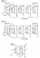
- the figure Fig. 2 shows a method sequence according to the invention for the arc-free switching on an air-insulated grounding switch 2 using an additional separation point 5a, 5b.
- the air-insulated earthing switch 2 and the second interrupter unit 3 as a vacuum switch and a separating point 5a, 5b arranged between the air-insulated earthing switch 2 and the vacuum interrupter 3 are opened.
- the separation point 5a, 5b is now closed first and then made an electrical connection of the line 7 via the vacuum interrupter chamber 3.
- An optionally resulting arc is deleted within the vacuum interrupter chamber 3.
- the fixed main contact 4 a of the air-insulated grounding switch 2 is closed, in which case now no arc can occur.
- the vacuum interrupter chamber 3 is subsequently separated from the electrical line 7 by means of the separation point 5a, 5b.
- FIG. 3 shows a turn-off operation according to the invention of arc-free switching of an air-insulated earthing switch 2 in conjunction with a vacuum interrupter chamber 3 as a second interrupter unit and a separation point 5a, 5b.
- the movable main contact 4b of the air-oiled grounding switch 2 is subsequently removed from the fixed main contact 4a.
- the electrical connection is made in this phase exclusively via the vacuum interrupter chamber 3 as a second interrupter unit.
- the contacts of the vacuum interrupter chamber 3 are also opened, so that an optionally resulting arc exclusively in the vacuum interrupter chamber 3 ignites.
- the fixed main contact 4a of the air-insulated grounding switch 2 is now far enough away from the main movable contact 4b to ignite an arc in the air between the main contacts 4a, 4b due to the separation distance.
- the separation point 5a, 5b is opened, so that the electrical connection is now canceled.
- the kinematics in the main flow path is used to make the appropriate switching operation.
- the movement of the movable main contact 4b is used for the force to be used for closing or opening the separation point 5a, 5b and the vacuum interrupter chamber 3 as a second interrupter unit.
- the vacuum interrupter chamber 3 does not need its own power supply and it is also no auxiliary flow path parallel to the earth current necessary.
- the figure Fig. 4 shows a circuit diagram of the switchgear 1 according to the invention with a arranged parallel to the second interrupter unit 3 surge arrester as a third interrupter unit 8.
- the parallel to the earthing switch 2 arranged as a first interrupter vacuum interrupter chamber 3 as the second interrupter unit is additionally protected by the third interrupter unit 8 as a spark gap and limited in voltage ,
- the vacuum chamber 3 can be dimensioned smaller than the earthing switch 2 with respect to the voltage and current resistance.
- further interrupter units may additionally be arranged in parallel and / or in series with respect to the vacuum interrupter chamber 3 in the electrical switchgear 1.
Landscapes
- High-Tension Arc-Extinguishing Switches Without Spraying Means (AREA)
- Gas-Insulated Switchgears (AREA)
- Keying Circuit Devices (AREA)
Claims (9)
- Appareil ( 1 ) électrique de manoeuvre ayant un commutateur ( 2 ) de mise à la terre à isolation par de l'air pour la coupure et la liaison d'une ligne ( 7 ) électrique, dans lequel, dans l'appareil ( 1 ) électrique de manoeuvre, au moins une deuxième unité ( 3 ) de coupure presque fermée est reliée au commutateur ( 2 ) de mise à la terre à isolation par de l'air et les décharges de tension, se créant à la liaison ou à la coupure de la ligne ( 7 ) électrique, se produisent sous forme d'arcs électriques dans la deuxième unité ( 3 ) de coupure et la deuxième unité ( 3 ) de coupure peut être commutée, à la liaison de la ligne ( 7 ) électrique, avant le commutateur ( 2 ) de mise à la terre à isolation par de l'air et, à la coupure de la ligne ( 7 ) électrique, après le commutateur ( 2 ) de mise à la terre à isolation par de l'air, caractérisé en ce qu'un sectionneur ( 5a, 5b ) est monté entre le commutateur ( 2 ) de mise à la terre à isolation par de l'air et la deuxième unité ( 3 ) de coupure et, au moyen d'un dispositif ( 6 ) de réception, une première partie du sectionneur ( 5a ), se trouvant sur un contact ( 4b ) principal mobile du commutateur ( 2 ) de mise à la terre à isolation par de l'air, produit un contact avec la deuxième partie du sectionneur ( 5b ).
- Appareil ( 1 ) électrique de manoeuvre suivant la revendication 1,
caractérisé en ce que
la deuxième unité ( 3 ) de coupure est un disjoncteur et/ou un commutateur de charge et/ou un sectionneur et/ou une chambre d'interrupteur à vide et/ou un dispositif de dérivation de surtensions. - Appareil ( 1 ) électrique de manoeuvre suivant l'une des revendications 1 à 2,
caractérisé en ce que
la deuxième unité ( 3 ) de coupure est montée du côté du potentiel de tension s'appliquant à l'appareil ( 1 ) de manoeuvre, notamment du côté du potentiel de la haute tension. - Appareil ( 1 ) électrique de manoeuvre suivant l'une des revendications 1 à 3,
caractérisé en ce que
au moins une autre unité ( 8 ) de coupure est, pour l'évacuation de surtensions, montée en parallèle et/ou en série avec la deuxième unité ( 3 ) de coupure. - Appareil ( 1 ) électrique de manoeuvre suivant la revendication 4,
caractérisé en ce que
la troisième unité ( 8 ) de coupure est un dispositif de dérivation de surtensions. - Appareil ( 1 ) électrique de manoeuvre suivant l'une des revendications 1 à 5,
caractérisé en ce que
la deuxième unité ( 3 ) de coupure est intégrée dans un contact ( 4a ) fixe d'un commutateur ( 2 ) de mise à la terre en tant que première unité de coupure. - Appareil ( 1 ) électrique de manoeuvre suivant l'une des revendications 1 à 6,
caractérisé en ce que
la deuxième unité ( 3 ) de coupure est montée en parallèle et/ou en série avec la première unité ( 2 ) de coupure. - Procédé de commutation d'un commutateur ( 2 ) de mise à la terre à isolation par de l'air d'une ligne ( 7 ) électrique reliée au commutateur de mise à la terre à isolation par de l'air par une deuxième unité ( 3 ) de coupure montée en parallèle au commutateur ( 2 ) de mise à la terre à isolation par de l'air, la deuxième unité ( 3 ) de coupure étant fermée, lors de liaison de la ligne ( 7 ) électrique, avant le commutateur ( 2 ) de mise à la terre à isolation par de l'air et, lors de la coupure de la ligne ( 7 ) électrique, d'abord le commutateur ( 2 ) de mise à la terre à isolation par de l'air et seulement ensuite la deuxième unité ( 3 ) de coupure étant séparés de la ligne ( 7 ) électrique, dans lequel, par un dispositif ( 6 ) de réception, une première partie d'un sectionneur ( 5a ) se trouvant sur un contact ( 4d ) principal mobile du commutateur ( 2 ) de mise à la terre à isolation par de l'air produit un contact avec la deuxième partie d'un sectionneur ( 5b ).
- Procédé suivant la revendication 8,
caractérisé en ce que,
dans l'utilisation du point de ( 5a, 5b ) de sectionnement comme liaison entre le commutateur ( 2 ) de mise à la terre à isolation par de l'air et la deuxième unité ( 3 ) de coupure lors de l'opération de connexion, d'abord le point ( 5a, 5b ) de sectionnement, ensuite la deuxième unité ( 3 ) de coupure, après le commutateur ( 2 ) de mise à la terre à isolation par de l'air sont fermés et, lorsque la liaison de la ligne est ménagée, le point ( 5a, 5b ) de sectionnement est ouvert à nouveau et, lors de la déconnexion, d'abord le point ( 5a, 5b ) de sectionnement ouvert est fermé, après le commutateur ( 2 ) de mise à la terre à isolation par de l'air est ouvert, après la deuxième unité ( 3 ) de sectionnement est ouverte avec production apparaissant, le cas échéant, d'un arc électrique et, après le sectionnement complet de la ligne ( 7 ) électrique, le point ( 5a, 5b ) de sectionnement est ouvert à nouveau.
Applications Claiming Priority (2)
| Application Number | Priority Date | Filing Date | Title |
|---|---|---|---|
| DE102006008933A DE102006008933B4 (de) | 2006-02-22 | 2006-02-22 | Elektrisches Schaltgerät |
| PCT/EP2007/051499 WO2007096302A1 (fr) | 2006-02-22 | 2007-02-16 | Commutateur électrique |
Publications (2)
| Publication Number | Publication Date |
|---|---|
| EP1991999A1 EP1991999A1 (fr) | 2008-11-19 |
| EP1991999B1 true EP1991999B1 (fr) | 2013-12-25 |
Family
ID=38008270
Family Applications (1)
| Application Number | Title | Priority Date | Filing Date |
|---|---|---|---|
| EP20070704621 Ceased EP1991999B1 (fr) | 2006-02-22 | 2007-02-16 | Commutateur électrique |
Country Status (8)
| Country | Link |
|---|---|
| US (1) | US7986061B2 (fr) |
| EP (1) | EP1991999B1 (fr) |
| CN (1) | CN101385108B (fr) |
| BR (1) | BRPI0708214B8 (fr) |
| DE (1) | DE102006008933B4 (fr) |
| MX (1) | MX2008010819A (fr) |
| RU (1) | RU2410788C2 (fr) |
| WO (1) | WO2007096302A1 (fr) |
Families Citing this family (9)
| Publication number | Priority date | Publication date | Assignee | Title |
|---|---|---|---|---|
| FR2946180B1 (fr) * | 2009-05-26 | 2012-12-14 | Areva T & D Sa | Dispositif d'accrochage et de verrouillage interne a un interrupteur ou a un disjoncteur. |
| EP2302748B1 (fr) * | 2009-09-23 | 2012-05-16 | ABB Technology | Appareil de commutation moyenne ou haute tension et procédé de mise à la terre |
| FR2980633B1 (fr) * | 2011-09-27 | 2013-09-06 | Schneider Electric Ind Sas | Appareillage de distribution electrique moyenne tension |
| EP2731120A1 (fr) * | 2012-11-08 | 2014-05-14 | ABB Technology AG | Système d'interrupteur à vide pour disjoncteur moyenne tension avec des contacts TMF en forme de coupe |
| CN104124104B (zh) * | 2013-04-25 | 2016-08-03 | 国家电网公司 | 一种具有开合感应电流能力的接地开关 |
| WO2015004242A1 (fr) * | 2013-07-12 | 2015-01-15 | Bayer Cropscience Nv | Plantes mutantes tolérantes à un herbicide inhibiteur de l'als |
| DE102019213320A1 (de) * | 2019-09-03 | 2021-03-04 | Siemens Energy Global GmbH & Co. KG | Einsäulen-Trennschalter mit Vakuum-Schaltröhre als Hilfskontaktsystem |
| ES1239274Y (es) * | 2019-10-14 | 2020-03-24 | Ormazabal Y Cia S L U | Aparamenta eléctrica para instalaciones de generación de energía eléctrica |
| FR3130446B1 (fr) * | 2021-12-13 | 2025-11-21 | Schneider Electric Ind Sas | Appareil de coupure de courant sur une ligne électrique comprenant une ampoule à vide |
Family Cites Families (10)
| Publication number | Priority date | Publication date | Assignee | Title |
|---|---|---|---|---|
| DE2522525A1 (de) * | 1975-05-21 | 1976-12-02 | Driescher Eltech Werk | Lasttrennschalter, insbesondere fuer den betrieb in einem mittelspannungsbereich |
| US4376271A (en) * | 1981-06-18 | 1983-03-08 | Siemens-Allis, Inc. | Polarized DC contactors |
| US5070252A (en) * | 1990-04-03 | 1991-12-03 | Automatic Switch Company | Automatic transfer switch |
| FR2680911B1 (fr) * | 1991-08-28 | 1995-01-20 | Gec Alsthom Engergie Inc | Sectionneur de terre a pouvoir de coupure. |
| FR2719154B1 (fr) * | 1994-04-25 | 1996-06-07 | Merlin Gerin | Interrupteur électrique moyenne tension. |
| FR2722912B1 (fr) * | 1994-07-20 | 1996-09-13 | Schneider Electric Sa | Interrupteurs electriques moyenne tension |
| RU2117351C1 (ru) * | 1997-03-11 | 1998-08-10 | Владимир Леонтьевич Лотоцкий | Коммутирующее устройство |
| DE19918077C1 (de) * | 1999-04-21 | 2000-11-09 | Driescher Eltech Werk | Lastschalter |
| DE19954460C2 (de) * | 1999-11-12 | 2002-02-28 | Pilz Gmbh & Co | Sicherheitsschaltgerät zum Ein- und sicheren Ausschalten eines elektrischen Verbrauchers, insbesondere einer elektrisch angetriebenen Maschine |
| DE102005051065B4 (de) * | 2005-10-25 | 2011-12-08 | Infineon Technologies Ag | Integrierte Halbleiterschaltung zum Zuschalten einer Spannungsdomäne |
-
2006
- 2006-02-22 DE DE102006008933A patent/DE102006008933B4/de not_active Expired - Fee Related
-
2007
- 2007-02-16 WO PCT/EP2007/051499 patent/WO2007096302A1/fr not_active Ceased
- 2007-02-16 US US12/280,251 patent/US7986061B2/en not_active Expired - Fee Related
- 2007-02-16 EP EP20070704621 patent/EP1991999B1/fr not_active Ceased
- 2007-02-16 RU RU2008137648A patent/RU2410788C2/ru active
- 2007-02-16 CN CN2007800058636A patent/CN101385108B/zh not_active Expired - Fee Related
- 2007-02-16 MX MX2008010819A patent/MX2008010819A/es active IP Right Grant
- 2007-02-16 BR BRPI0708214A patent/BRPI0708214B8/pt not_active IP Right Cessation
Also Published As
| Publication number | Publication date |
|---|---|
| BRPI0708214A2 (pt) | 2011-05-17 |
| MX2008010819A (es) | 2008-09-05 |
| BRPI0708214B1 (pt) | 2018-06-26 |
| BRPI0708214B8 (pt) | 2023-04-25 |
| CN101385108B (zh) | 2013-10-02 |
| US7986061B2 (en) | 2011-07-26 |
| DE102006008933A1 (de) | 2007-08-30 |
| US20090020506A1 (en) | 2009-01-22 |
| RU2008137648A (ru) | 2010-03-27 |
| EP1991999A1 (fr) | 2008-11-19 |
| RU2410788C2 (ru) | 2011-01-27 |
| DE102006008933B4 (de) | 2009-06-18 |
| CN101385108A (zh) | 2009-03-11 |
| WO2007096302A1 (fr) | 2007-08-30 |
Similar Documents
| Publication | Publication Date | Title |
|---|---|---|
| EP1991999B1 (fr) | Commutateur électrique | |
| EP2737588B1 (fr) | Disjoncteur de protection de circuit à tension continue | |
| EP2845213B1 (fr) | Sectionneur à coupure sous charge à trois positions pour installations électriques moyenne tension | |
| EP3091550B1 (fr) | Dispositif de commutation hybride | |
| EP3797436A1 (fr) | Appareil de commutation et procédé | |
| DE69013300T2 (de) | Überspannungsbegrenzender Schalter. | |
| EP0239783A2 (fr) | Installation d'interrupteur électrique pour haute tension | |
| EP3061111B1 (fr) | Dispositif et procédé pour commuter un courant continu | |
| EP2732521A1 (fr) | Disjoncteur de protection de circuit à tension continue | |
| EP1037232B1 (fr) | Appareil de commutation à haute tension avec montage en série d'au moins deux interrupteurs sous vide pour le fonctionnement de l'appareil de commutation à haute tension | |
| EP3443631A1 (fr) | Dispositif de déconnexion et de commutation pour la protection contre les surtensions, en particulier pour systèmes cc | |
| DE69109749T2 (de) | Leistungsschalter mit eingebautem Varistor. | |
| DE102012200962A1 (de) | Schaltgerät, insbesondere Lasttrennschalter, für Mittelspannungs-Schaltanlagen | |
| EP1675142B1 (fr) | Système de contact pour un appareil de commutation électrique | |
| EP0763840B1 (fr) | Disjoncteur à haute tension dans un boítier métallique isolé par gaz | |
| WO2013072467A9 (fr) | Procédé et ensemble de circuits permettant de séparer une connexion électrique entre deux points de connexion | |
| EP2122647B1 (fr) | Réseau électrique à courant continu pour navires et installations en mer présentant une sécurité de coupure accrue | |
| EP1187157B1 (fr) | Sectionneur | |
| DE102013224834A1 (de) | Wechselspannungslasttrennschalter für Fahrleitungen eines Bahnstromversorgungsnetzes und Verfahren zum Betreiben eines Wechselspannungslasttrennschalters | |
| WO2018083309A2 (fr) | Sectionneur de puissance, dispositif de coupure pourvu d'un sectionneur de puissance, procédé de fonctionnement d'un dispositif de coupure et utilisation d'un sectionneur de puissance | |
| DE102022118372B4 (de) | Anordnung zum Unterbrechen von Strom in einer Hochspannungsleitung und Verfahren zum Betreiben einer solchen Anordnung | |
| EP3417468B1 (fr) | Circuit de commutation, convertisseur comportant une installation de commutation ainsi qu'un procédé de protection du circuit convertisseur | |
| DE102023200524B3 (de) | Anschlussklemme und Reiheneinbaugerät | |
| EP1347482B1 (fr) | Réseau de distribution du courant | |
| DE202025101393U1 (de) | Lasttrennschalter |
Legal Events
| Date | Code | Title | Description |
|---|---|---|---|
| PUAI | Public reference made under article 153(3) epc to a published international application that has entered the european phase |
Free format text: ORIGINAL CODE: 0009012 |
|
| 17P | Request for examination filed |
Effective date: 20080731 |
|
| AK | Designated contracting states |
Kind code of ref document: A1 Designated state(s): DE FR GB |
|
| DAX | Request for extension of the european patent (deleted) | ||
| RBV | Designated contracting states (corrected) |
Designated state(s): DE FR GB |
|
| 17Q | First examination report despatched |
Effective date: 20091015 |
|
| RAP1 | Party data changed (applicant data changed or rights of an application transferred) |
Owner name: SIEMENS AKTIENGESELLSCHAFT |
|
| GRAP | Despatch of communication of intention to grant a patent |
Free format text: ORIGINAL CODE: EPIDOSNIGR1 |
|
| INTG | Intention to grant announced |
Effective date: 20130708 |
|
| GRAS | Grant fee paid |
Free format text: ORIGINAL CODE: EPIDOSNIGR3 |
|
| GRAA | (expected) grant |
Free format text: ORIGINAL CODE: 0009210 |
|
| AK | Designated contracting states |
Kind code of ref document: B1 Designated state(s): DE FR GB |
|
| REG | Reference to a national code |
Ref country code: GB Ref legal event code: FG4D Free format text: NOT ENGLISH |
|
| REG | Reference to a national code |
Ref country code: DE Ref legal event code: R096 Ref document number: 502007012631 Country of ref document: DE Effective date: 20140213 |
|
| REG | Reference to a national code |
Ref country code: DE Ref legal event code: R097 Ref document number: 502007012631 Country of ref document: DE |
|
| PLBE | No opposition filed within time limit |
Free format text: ORIGINAL CODE: 0009261 |
|
| STAA | Information on the status of an ep patent application or granted ep patent |
Free format text: STATUS: NO OPPOSITION FILED WITHIN TIME LIMIT |
|
| 26N | No opposition filed |
Effective date: 20140926 |
|
| REG | Reference to a national code |
Ref country code: DE Ref legal event code: R097 Ref document number: 502007012631 Country of ref document: DE Effective date: 20140926 |
|
| REG | Reference to a national code |
Ref country code: FR Ref legal event code: PLFP Year of fee payment: 10 |
|
| REG | Reference to a national code |
Ref country code: FR Ref legal event code: PLFP Year of fee payment: 11 |
|
| REG | Reference to a national code |
Ref country code: FR Ref legal event code: PLFP Year of fee payment: 12 |
|
| REG | Reference to a national code |
Ref country code: DE Ref legal event code: R081 Ref document number: 502007012631 Country of ref document: DE Owner name: SIEMENS ENERGY GLOBAL GMBH & CO. KG, DE Free format text: FORMER OWNER: SIEMENS AKTIENGESELLSCHAFT, 80333 MUENCHEN, DE |
|
| PGFP | Annual fee paid to national office [announced via postgrant information from national office to epo] |
Ref country code: FR Payment date: 20210215 Year of fee payment: 15 |
|
| PGFP | Annual fee paid to national office [announced via postgrant information from national office to epo] |
Ref country code: GB Payment date: 20210302 Year of fee payment: 15 |
|
| PGFP | Annual fee paid to national office [announced via postgrant information from national office to epo] |
Ref country code: DE Payment date: 20210419 Year of fee payment: 15 |
|
| REG | Reference to a national code |
Ref country code: DE Ref legal event code: R119 Ref document number: 502007012631 Country of ref document: DE |
|
| GBPC | Gb: european patent ceased through non-payment of renewal fee |
Effective date: 20220216 |
|
| PG25 | Lapsed in a contracting state [announced via postgrant information from national office to epo] |
Ref country code: FR Free format text: LAPSE BECAUSE OF NON-PAYMENT OF DUE FEES Effective date: 20220228 |
|
| PG25 | Lapsed in a contracting state [announced via postgrant information from national office to epo] |
Ref country code: GB Free format text: LAPSE BECAUSE OF NON-PAYMENT OF DUE FEES Effective date: 20220216 Ref country code: DE Free format text: LAPSE BECAUSE OF NON-PAYMENT OF DUE FEES Effective date: 20220901 |