EP1992222A1 - Ensemble d'abreuvoir - Google Patents
Ensemble d'abreuvoir Download PDFInfo
- Publication number
- EP1992222A1 EP1992222A1 EP08008988A EP08008988A EP1992222A1 EP 1992222 A1 EP1992222 A1 EP 1992222A1 EP 08008988 A EP08008988 A EP 08008988A EP 08008988 A EP08008988 A EP 08008988A EP 1992222 A1 EP1992222 A1 EP 1992222A1
- Authority
- EP
- European Patent Office
- Prior art keywords
- trough
- coupling device
- drinking
- assembly
- mouth
- Prior art date
- Legal status (The legal status is an assumption and is not a legal conclusion. Google has not performed a legal analysis and makes no representation as to the accuracy of the status listed.)
- Withdrawn
Links
- 230000035622 drinking Effects 0.000 title claims abstract description 32
- 230000008878 coupling Effects 0.000 claims abstract description 33
- 238000010168 coupling process Methods 0.000 claims abstract description 33
- 238000005859 coupling reaction Methods 0.000 claims abstract description 33
- 238000003466 welding Methods 0.000 description 2
- 230000000712 assembly Effects 0.000 description 1
- 238000000429 assembly Methods 0.000 description 1
- 230000000694 effects Effects 0.000 description 1
- 230000001771 impaired effect Effects 0.000 description 1
- JEIPFZHSYJVQDO-UHFFFAOYSA-N iron(III) oxide Inorganic materials O=[Fe]O[Fe]=O JEIPFZHSYJVQDO-UHFFFAOYSA-N 0.000 description 1
- 239000000463 material Substances 0.000 description 1
- 239000002184 metal Substances 0.000 description 1
- 229920003023 plastic Polymers 0.000 description 1
- 239000004033 plastic Substances 0.000 description 1
Images


Classifications
-
- A—HUMAN NECESSITIES
- A01—AGRICULTURE; FORESTRY; ANIMAL HUSBANDRY; HUNTING; TRAPPING; FISHING
- A01K—ANIMAL HUSBANDRY; AVICULTURE; APICULTURE; PISCICULTURE; FISHING; REARING OR BREEDING ANIMALS, NOT OTHERWISE PROVIDED FOR; NEW BREEDS OF ANIMALS
- A01K7/00—Watering equipment for stock or game
Definitions
- the present invention relates to animal drinking troughs.
- pivotally mount a drinking trough between two support stands Conventionally, either end of the trough is provided with a respective pivot bar or shaft which slots into a respective stand to allow pivoting movement of the trough.
- the pivot bars are fixed to the ends of the trough by, for example, welding.
- pivot bars are subject to wear and rust but cannot be replaced without replacing the entire trough.
- troughs do not lend themselves to space-efficient transport and storage.
- the invention provides a drinking trough assembly comprising a trough, and at least one coupling device for coupling the trough to a support, wherein said at least one coupling device is removably connectable to the trough.
- said at least one coupling device is removably connectable to the trough adjacent the mouth of the trough, preferably to a lip located at or adjacent the mouth.
- said at least one coupling device is connectable to an end or side of the trough which is tapered, or obliquely disposed, with respect to the mouth of the trough, said at least one coupling device being suspended in use from said lip or mouth to define a gap between said at least one coupling device and said tapered end or side.
- said at least one coupling device has a body, for example in the form of a plate, which is substantially perpendicularly disposed to the mouth of the trough.
- Said at least one coupling device typically includes a bar or shaft for coupling with a support stand or other support, the bar or shaft usually projecting substantially perpendicularly from the body of the coupling device.
- the trough is substantially rectangular in plan cross-section, with both ends and typically also both sides being tapered.
- a respective coupling device is usually provided at each end. It will be understood, however, that the invention may be used with troughs of other shapes.
- a drinking trough assembly comprising a trough adapted to be stackable in nested relationship with one or more identical troughs, and a support structure being removably connectable to the drinking trough adjacent the mouth of the trough, whereby, when connected to the drinking trough, said support structure is adapted to support the drinking trough on a surface, said supporting structure being removable from the drinking trough to permit the trough to be stacked with one or more identical troughs.
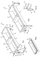
- the drinking trough assembly 10 comprises a trough 12 mounted between two support brackets or stands 14, 16. To this end, a respective shaft or bar 18 (only one visible) is provided at each end 13, 15 of the trough 12, projecting laterally from the respective end 13, 15.
- the stands 14, 16 include a respective bush or sleeve 20 for receiving the respective shaft 18.
- the shaft 18 Once inserted into the sleeve 20, the shaft 18 may be secured by, for example, a pin 22 or other suitable fixing means.
- the preferred arrangement is such that each shaft 18 is able to pivot upward along its longitudinal axis with respect to the respective sleeve 20.
- the shafts 18 are substantially horizontally disposed in use so that the trough may pivot about a substantially horizontal axis.
- Figure 1 shows the trough assembly 10 in a first mode of use in which the stands 14, 16, engage with a ground surface (not shown), the trough 12 being supported above the ground surface by the stands 14, 16.
- the trough 12 may be fixed in position with respect to stands 14,16 by means of a rod 24 or other rigid member extending between the trough 12 and at least one of the stands 14, 16.
- at least one of the stands 14 is provided with a socket 26 for receiving the rod 24, the trough 12 carrying a second socket 28 for receiving another portion of the rod 24.
- Figure 2 shows a trough assembly 10 in a second mode of use in which the mode of orientation between the trough 12 and the stands 14, 16 is displaced by approximately 90° with respect to the orientation shown in Figure 1 .
- the stands 14, 16 may be fixed on, for example, a wall surface or other substantially vertical surface.
- the rod 24 may be used to fix the orientation of the trough 12 with respect to the stands 14, 16, sockets 28, 30 being provided for receiving the rod 24.
- a housing 34 for a ball cock (not shown) may also be provided in the trough 12.
- the stands 14, 16 are removable from the shafts 18.
- the shafts 18 can also be removed from the troughs 12.
- the ends 13, 15 and sides 17, 18 of the trough 12 are tapered.
- the ends 13, 15 and sides 17, 18 of the trough 12 are obliquely disposed with respect to the plane in which the mouth of the trough 12 lies.
- Figure 3 shows, by way of example, the three troughs 12, being stacked one within another.
- each shaft 18, is removably coupled to the respective ends 13, 15 of the trough 12 by means of a respective coupling device in the preferred form of support bracket 36 (only one visible), each support bracket 36 being releasably fixable to the trough 12 at a location adjacent to mouth of the trough 12.
- the trough 12 includes a flange or lip 32 at least at each end 13, 15.
- the lip 32 is, in a preferred embodiment, integrally formed with the trough 12 and may, for example, be formed by folding a portion of the material, typically metal or plastics, used to make the trough 12.
- the lip 32 includes a lateral portion 33 which preferably is disposed in a plane which is substantially coincident with, or substantially parallel with, the plane in which the mouth of the trough 12 lies. In a preferred embodiment, the lip 32 extends substantially around the entire mouth of the trough 12.
- the bracket 36 comprises a plate 38 from which the shaft 18 8 projects.
- the shaft 18 is preferably fixed to the plate 38 by any suitable means, e.g. welding.
- the shaft 18 projects substantially perpendicularly from the plate 38.
- a flange 40 is provided at one end of the plate 38.
- the flange 40 projects substantially perpendicularly from the plate 38.
- the flange 40 may, as illustrated, extend along one or both sides of the plate 38 to lend strength to the plate 38.
- the bracket 36 is connectable to the trough 12 by releasable fixing means.
- the fixing means take the form of one or more screws 42, or other fixings.
- the bracket 36 may be, for example, releasably mountable to the trough 12 by means of a clip mechanism (not illustrated), or a friction fit mechanism (not illustrated).
- the bracket 36 is connectable to the lip 32 at the respective ends 13, 15 of the trough 12. It is advantageous to form the screw-receiving apertures 44 in the lip 32 rather than the body of the trough 12 itself. Corresponding screw-receiving apertures 44 are also formed in the flange 40 of the bracket 36 and so, when the bracket 36 is engaged with the lip 32, the flange 40 engages with the in use underside of the lip 32.
- the bracket 36 when the bracket 36 is fitted to the trough 12, the plates 38 extend substantially perpendicularly with respect to the mouth of the trough and the shaft 18 is therefore disposed in the plane which is substantially parallel with the plane of the mouth of the trough.
- Figure 5 shows that the bracket 36 is in effect suspended from the lip 32 and is spaced apart from the end 13 of the trough 12.
- the lip 32 is provided with a down turned portion 35.
- the bracket 36 may be fixed to the lip 32 such that the flange 40 engages with the underside of the lip 32, while the plate 38 engages with the down turned portion 35. This improves the stability of the connection between the bracket 36 and the trough 12.
- the support stands 14, 16 and the brackets 36 are removed, and this, in conjunction with the tapered ends and sides of the trough 12 allow the troughs 12 to be stacked one inside another as illustrated in Figure 3 . Moreover, should a shaft 18 become worn, rusted or otherwise impaired, it can readily be replaced without having to replace the entire trough 12.
Landscapes
- Life Sciences & Earth Sciences (AREA)
- Environmental Sciences (AREA)
- Animal Husbandry (AREA)
- Biodiversity & Conservation Biology (AREA)
- Laying Of Electric Cables Or Lines Outside (AREA)
Applications Claiming Priority (1)
| Application Number | Priority Date | Filing Date | Title |
|---|---|---|---|
| GBGB0709414.7A GB0709414D0 (en) | 2007-05-16 | 2007-05-16 | A drinking trough assembly |
Publications (1)
| Publication Number | Publication Date |
|---|---|
| EP1992222A1 true EP1992222A1 (fr) | 2008-11-19 |
Family
ID=38234551
Family Applications (1)
| Application Number | Title | Priority Date | Filing Date |
|---|---|---|---|
| EP08008988A Withdrawn EP1992222A1 (fr) | 2007-05-16 | 2008-05-15 | Ensemble d'abreuvoir |
Country Status (3)
| Country | Link |
|---|---|
| US (1) | US20090007851A1 (fr) |
| EP (1) | EP1992222A1 (fr) |
| GB (1) | GB0709414D0 (fr) |
Cited By (1)
| Publication number | Priority date | Publication date | Assignee | Title |
|---|---|---|---|---|
| EP2534944A1 (fr) * | 2011-06-14 | 2012-12-19 | La Buvette | Cuve pour un abreuvoir collectif |
Families Citing this family (2)
| Publication number | Priority date | Publication date | Assignee | Title |
|---|---|---|---|---|
| USD854256S1 (en) * | 2017-09-26 | 2019-07-16 | Emiliano Gabriel Flores | Integrated pet water bottle with bowl |
| CN119183970A (zh) * | 2024-09-18 | 2024-12-27 | 巨星农牧有限公司 | 一种便于清洗的食槽 |
Citations (3)
| Publication number | Priority date | Publication date | Assignee | Title |
|---|---|---|---|---|
| GB191504134A (en) * | 1915-03-16 | 1915-10-07 | Francis Boyle Hooper | Improvements in Feed Troughs. |
| GB2268868A (en) * | 1992-05-06 | 1994-01-26 | Dennis Kilby Bell | Water trough mountings. |
| EP1502500A1 (fr) * | 2003-08-01 | 2005-02-02 | La Buvette | Abreuvoir basculant |
Family Cites Families (22)
| Publication number | Priority date | Publication date | Assignee | Title |
|---|---|---|---|---|
| US654427A (en) * | 1900-03-30 | 1900-07-24 | John C F Atsatt | Poultry-feeder. |
| US1408675A (en) * | 1921-06-11 | 1922-03-07 | Anthony J Wimberg | Vise stand |
| US1522084A (en) * | 1924-03-26 | 1925-01-06 | James M Swearingen | Feeding trough |
| US1899519A (en) * | 1930-04-30 | 1933-02-28 | Neilsen Alfred | Watering trough for poultry |
| US2011684A (en) * | 1930-08-18 | 1935-08-20 | Perry S Martin | Combination feed trough and drinking fountain |
| US1980640A (en) * | 1932-11-12 | 1934-11-13 | Schneider Georg | Drinking trough for animals |
| US2517865A (en) * | 1947-12-17 | 1950-08-08 | Jr James Gilmour | Adjustable poultry watering trough |
| US2576154A (en) * | 1948-07-23 | 1951-11-27 | Fred C Trautvetter | Adjustable filling device for feed troughs |
| US2843087A (en) * | 1956-12-11 | 1958-07-15 | Veachel L Gray | Poultry drinker |
| US2995110A (en) * | 1959-01-05 | 1961-08-08 | Woodrow J Wiley | Poultry watering trough |
| US3052215A (en) * | 1961-03-31 | 1962-09-04 | William J Shold | Poultry waterer |
| US3166048A (en) * | 1961-12-18 | 1965-01-19 | Automatic Poultry Feeder Compa | Trough waterer |
| US3241526A (en) * | 1963-11-18 | 1966-03-22 | Big Dutchman Inc | Poultry watering device |
| US3661122A (en) * | 1968-01-10 | 1972-05-09 | Charles H Willauer Jr | Watering system for fowl |
| US3841268A (en) * | 1973-04-16 | 1974-10-15 | R Bunger | Livestock watering trough |
| US4149490A (en) * | 1977-01-13 | 1979-04-17 | English Ernest W | Poultry watering method |
| US4217857A (en) * | 1978-04-24 | 1980-08-19 | M.H.G., Inc. | Pet relief station |
| US4258665A (en) * | 1979-05-14 | 1981-03-31 | Coots Warren R | Adjustable foal feeder |
| CA1310234C (fr) * | 1989-06-15 | 1992-11-17 | Lyle Alfred Bradtrud | Auge pour l'alimentation du betail |
| US5738037A (en) * | 1996-04-30 | 1998-04-14 | Mahan; Joe B. | Watering trough for horses and other animals |
| US20060272587A1 (en) * | 2005-06-07 | 2006-12-07 | Roy Gordon | Rotating feed bunk |
| USD556952S1 (en) * | 2006-05-08 | 2007-12-04 | Petersen Chris C | Cattle waterer |
-
2007
- 2007-05-16 GB GBGB0709414.7A patent/GB0709414D0/en not_active Ceased
-
2008
- 2008-05-15 EP EP08008988A patent/EP1992222A1/fr not_active Withdrawn
- 2008-05-15 US US12/121,126 patent/US20090007851A1/en not_active Abandoned
Patent Citations (3)
| Publication number | Priority date | Publication date | Assignee | Title |
|---|---|---|---|---|
| GB191504134A (en) * | 1915-03-16 | 1915-10-07 | Francis Boyle Hooper | Improvements in Feed Troughs. |
| GB2268868A (en) * | 1992-05-06 | 1994-01-26 | Dennis Kilby Bell | Water trough mountings. |
| EP1502500A1 (fr) * | 2003-08-01 | 2005-02-02 | La Buvette | Abreuvoir basculant |
Cited By (2)
| Publication number | Priority date | Publication date | Assignee | Title |
|---|---|---|---|---|
| EP2534944A1 (fr) * | 2011-06-14 | 2012-12-19 | La Buvette | Cuve pour un abreuvoir collectif |
| FR2976453A1 (fr) * | 2011-06-14 | 2012-12-21 | Buvette | Cuve pour abreuvoir collectif |
Also Published As
| Publication number | Publication date |
|---|---|
| GB0709414D0 (en) | 2007-06-27 |
| US20090007851A1 (en) | 2009-01-08 |
Similar Documents
| Publication | Publication Date | Title |
|---|---|---|
| US7900781B2 (en) | Storage system | |
| CN209892483U (zh) | 吊扇及其安装结构 | |
| US10448626B2 (en) | Fishing rod holder with a top mount receptacle for receiving a device mount | |
| US20080105633A1 (en) | Tiltable Mounting Bracket | |
| US7398951B1 (en) | Urinal holder | |
| US20120261362A1 (en) | Display support column | |
| US7066339B2 (en) | Adjustable hanging device | |
| EP1397062A2 (fr) | Port de peripherique configurable | |
| US20160353886A1 (en) | Television support and mounting kit | |
| US20090007851A1 (en) | Drinking Trough Assembly | |
| US20180079342A1 (en) | Beverage Container Holder for Mounting to the Exterior of a Vehicle | |
| US20210001470A1 (en) | Engine stand | |
| CN106998911A (zh) | 架子 | |
| AU2008340757B2 (en) | Guiding device for submersible motor agitators | |
| NO319472B1 (no) | System for avtagbart oppheng av hyller, skuffer eller lignende | |
| US9933111B1 (en) | Electronics mount | |
| US20250331681A1 (en) | Grill Grate Device | |
| US11154978B2 (en) | Engine stand | |
| US6536731B1 (en) | Structure for mounting rigging equipment | |
| US20250020981A1 (en) | Reversible l-bracket | |
| US20080278652A1 (en) | Monitor holder for providing stable support | |
| CA1157838A (fr) | Methode et dispositif d'assise et d'orientation d'un projecteur | |
| US20220390212A1 (en) | Target disc holder | |
| AU2003204394A1 (en) | Fixing Structure of Upper Panel and Drawer for Desk | |
| US12550872B2 (en) | Bird perch mounted to monitor |
Legal Events
| Date | Code | Title | Description |
|---|---|---|---|
| PUAI | Public reference made under article 153(3) epc to a published international application that has entered the european phase |
Free format text: ORIGINAL CODE: 0009012 |
|
| AK | Designated contracting states |
Kind code of ref document: A1 Designated state(s): AT BE BG CH CY CZ DE DK EE ES FI FR GB GR HR HU IE IS IT LI LT LU LV MC MT NL NO PL PT RO SE SI SK TR |
|
| AX | Request for extension of the european patent |
Extension state: AL BA MK RS |
|
| 17P | Request for examination filed |
Effective date: 20090519 |
|
| AKX | Designation fees paid |
Designated state(s): AT BE BG CH CY CZ DE DK EE ES FI FR GB GR HR HU IE IS IT LI LT LU LV MC MT NL NO PL PT RO SE SI SK TR |
|
| D17P | Request for examination filed (deleted) | ||
| R17P | Request for examination filed (corrected) |
Effective date: 20090728 |
|
| RBV | Designated contracting states (corrected) |
Designated state(s): AT BE BG CH CY CZ DE DK EE ES FI FR GB GR HR HU IE IS IT LI LT LU LV MC MT NL NO PL PT RO SE SI SK TR |
|
| 17Q | First examination report despatched |
Effective date: 20090821 |
|
| REG | Reference to a national code |
Ref country code: DE Ref legal event code: 8566 |
|
| STAA | Information on the status of an ep patent application or granted ep patent |
Free format text: STATUS: THE APPLICATION IS DEEMED TO BE WITHDRAWN |
|
| 18D | Application deemed to be withdrawn |
Effective date: 20100302 |