EP1992306A2 - Kieferorthopädisches Implantat - Google Patents
Kieferorthopädisches Implantat Download PDFInfo
- Publication number
- EP1992306A2 EP1992306A2 EP08162688A EP08162688A EP1992306A2 EP 1992306 A2 EP1992306 A2 EP 1992306A2 EP 08162688 A EP08162688 A EP 08162688A EP 08162688 A EP08162688 A EP 08162688A EP 1992306 A2 EP1992306 A2 EP 1992306A2
- Authority
- EP
- European Patent Office
- Prior art keywords
- mounting element
- implant according
- implant
- fastening means
- connecting piece
- Prior art date
- Legal status (The legal status is an assumption and is not a legal conclusion. Google has not performed a legal analysis and makes no representation as to the accuracy of the status listed.)
- Granted
Links
- 239000007943 implant Substances 0.000 title claims abstract description 80
- 210000000988 bone and bone Anatomy 0.000 claims abstract description 16
- 239000000463 material Substances 0.000 claims description 6
- RTAQQCXQSZGOHL-UHFFFAOYSA-N Titanium Chemical compound [Ti] RTAQQCXQSZGOHL-UHFFFAOYSA-N 0.000 claims description 3
- 239000010936 titanium Substances 0.000 claims description 3
- 229910052719 titanium Inorganic materials 0.000 claims description 3
- RKDVKSZUMVYZHH-UHFFFAOYSA-N 1,4-dioxane-2,5-dione Chemical compound O=C1COC(=O)CO1 RKDVKSZUMVYZHH-UHFFFAOYSA-N 0.000 claims description 2
- JJTUDXZGHPGLLC-IMJSIDKUSA-N 4511-42-6 Chemical compound C[C@@H]1OC(=O)[C@H](C)OC1=O JJTUDXZGHPGLLC-IMJSIDKUSA-N 0.000 claims description 2
- 229920000642 polymer Polymers 0.000 claims description 2
- 210000000056 organ Anatomy 0.000 abstract 2
- 230000008878 coupling Effects 0.000 description 6
- 238000010168 coupling process Methods 0.000 description 6
- 238000005859 coupling reaction Methods 0.000 description 6
- 229910052751 metal Inorganic materials 0.000 description 6
- 239000002184 metal Substances 0.000 description 6
- 210000000214 mouth Anatomy 0.000 description 6
- 206010052428 Wound Diseases 0.000 description 2
- 208000027418 Wounds and injury Diseases 0.000 description 2
- 210000003625 skull Anatomy 0.000 description 2
- 0 *C(CC1)C*1*=C Chemical compound *C(CC1)C*1*=C 0.000 description 1
- 206010002091 Anaesthesia Diseases 0.000 description 1
- 238000004026 adhesive bonding Methods 0.000 description 1
- 238000001949 anaesthesia Methods 0.000 description 1
- 230000037005 anaesthesia Effects 0.000 description 1
- 239000000560 biocompatible material Substances 0.000 description 1
- 230000015572 biosynthetic process Effects 0.000 description 1
- 230000006835 compression Effects 0.000 description 1
- 238000007906 compression Methods 0.000 description 1
- 238000010438 heat treatment Methods 0.000 description 1
- 238000002513 implantation Methods 0.000 description 1
- 238000001356 surgical procedure Methods 0.000 description 1
- 210000000216 zygoma Anatomy 0.000 description 1
Images



Classifications
-
- A—HUMAN NECESSITIES
- A61—MEDICAL OR VETERINARY SCIENCE; HYGIENE
- A61C—DENTISTRY; APPARATUS OR METHODS FOR ORAL OR DENTAL HYGIENE
- A61C8/00—Means to be fixed to the jaw-bone for consolidating natural teeth or for fixing dental prostheses thereon; Dental implants; Implanting tools
- A61C8/0018—Means to be fixed to the jaw-bone for consolidating natural teeth or for fixing dental prostheses thereon; Dental implants; Implanting tools characterised by the shape
- A61C8/0031—Juxtaosseous implants, i.e. implants lying over the outer surface of the jaw bone
-
- A—HUMAN NECESSITIES
- A61—MEDICAL OR VETERINARY SCIENCE; HYGIENE
- A61C—DENTISTRY; APPARATUS OR METHODS FOR ORAL OR DENTAL HYGIENE
- A61C7/00—Orthodontics, i.e. obtaining or maintaining the desired position of teeth, e.g. by straightening, evening, regulating, separating, or by correcting malocclusions
-
- A—HUMAN NECESSITIES
- A61—MEDICAL OR VETERINARY SCIENCE; HYGIENE
- A61C—DENTISTRY; APPARATUS OR METHODS FOR ORAL OR DENTAL HYGIENE
- A61C7/00—Orthodontics, i.e. obtaining or maintaining the desired position of teeth, e.g. by straightening, evening, regulating, separating, or by correcting malocclusions
- A61C7/12—Brackets; Arch wires; Combinations thereof; Accessories therefor
-
- A—HUMAN NECESSITIES
- A61—MEDICAL OR VETERINARY SCIENCE; HYGIENE
- A61C—DENTISTRY; APPARATUS OR METHODS FOR ORAL OR DENTAL HYGIENE
- A61C8/00—Means to be fixed to the jaw-bone for consolidating natural teeth or for fixing dental prostheses thereon; Dental implants; Implanting tools
- A61C8/0048—Connecting the upper structure to the implant, e.g. bridging bars
- A61C8/0075—Implant heads specially designed for receiving an upper structure
-
- A—HUMAN NECESSITIES
- A61—MEDICAL OR VETERINARY SCIENCE; HYGIENE
- A61C—DENTISTRY; APPARATUS OR METHODS FOR ORAL OR DENTAL HYGIENE
- A61C8/00—Means to be fixed to the jaw-bone for consolidating natural teeth or for fixing dental prostheses thereon; Dental implants; Implanting tools
- A61C8/0093—Features of implants not otherwise provided for
- A61C8/0096—Implants for use in orthodontic treatment
Definitions
- the present invention concerns an orthodontic implant which makes it possible to gradually move a person's teeth showing an incorrect implantation into an adjusted position by exerting an almost continuous pressure force or tensile force on these teeth.
- the means used according to the present state of the art for thus adjusting the position of a person's teeth comprise different sorts of braces which can be placed in an either or not removable manner in a person's mouth.
- an outer brace is moreover required, which exerts an additional force on the person's teeth or on the upper or lower jaw, for example via the neck.
- braces are particularly unpleasant to wear and they do not always make it possible to obtain a precise, reproducible distribution of power on the person's teeth or jaw.
- the invention aims to remedy these disadvantages by proposing an orthodontic implant as specified in claim 1 which makes it possible to change the position of a person's teeth in a simple and precise manner.
- an implant according to the invention the use of an outer brace is no longer required, and remarkably good results are obtained.
- WO 02/089682 which is not prior art under article 54(2) EPC, discloses an orthodontic implant with fastening means to be fixed to the jawbone and a mounting element for mounting orthodontic appliances, whereby the mounting element is connected to the fastening means by a connecting piece intended to pierce the gum.
- the orthodontic implant according to the invention has fastening means to be fixed to the bone of a person's upper jaw or lower jaw, and it further comprises a mounting element for mounting orthodontic appliances, whereby said mounting element is connected to the above-mentioned fastening means by means of a connecting piece which must extend through the gum surrounding the corresponding bone.
- said mounting element contains at least one bore hole which is provided with thread co-operating with a bolt which makes it possible to fix said appliances to the implant.
- said mounting element has at least one recess in which a corresponding coupling element of said appliances is to be mounted.
- said connecting piece is bent in order to make sure that the longitudinal axis of said recess extends almost parallel to the lateral surfaces of the teeth situated in the jaw upon which said implant must be fixed.
- said fastening means are formed of a plate which is provided with one or several recesses through which screws fit for fixing the implant to the bone of said upper or lower jaw.
- the above-mentioned mounting element is at least partially spherical.
- the above-mentioned connecting piece has a cross section with round angles, or a circular or elliptic cross section.
- Figure 1 is a schematic view in perspective of the implant according to the invention.
- Figure 2 is a schematic side view of a skull where the implant according to the invention is fixed to the upper jaw.
- Figure 3 is a schematic bottom view of an upper jaw onto which the implant according to the invention is attached.
- Figure 4 is a schematic side view of a skull where the implant according to the invention is fixed to the lower jaw.
- Figure 5 is a schematic side view of part of an upper jaw provided with the implant according to the invention, with orthodontic appliances.
- Figure 6 is a schematic side view of part of an upper jaw provided with the implant according to the invention, with different orthodontic appliances.
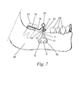
- Figure 7 is a schematic side view of part of a lower jaw which is provided with an orthodontic implant according to the invention.
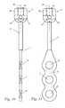
- Figure 8 is a schematic side view of an implant according to an interesting embodiment of the invention.
- Figure 9 is a schematic front view of the implant from figure 8 .
- Figure 10 is a schematic side view of an implant according to another embodiment of the invention.
- Figure 11 is a schematic front view of the implant from figure 10 .
- the invention in general concerns an orthodontic implant which makes it possible to connect orthodontic appliances, such as for example fixed braces, to the bone of a person's upper or lower jaw.
- Braces are known as such. With such braces, what are called brackets are fixed to the teeth. These brackets are mutually connected via a metal wire which makes it possible to exert an almost continuous force on the brackets so as to move certain teeth gradually into an adjusted position.
- the implant according to the invention is connected to this wire, or to one or several brackets, via a coupling element so as to exert a suitable force in order to adjust the position of the corresponding teeth.
- FIG. 1 represents a specific embodiment of an orthodontic implant according to the invention.
- This implant 1 has fastening means 2 to be fixed to the bone of an upper or lower jaw and a mounting element 3 for connecting orthodontic appliances to the implant 1.
- the fastening means 2 and the mounting element 3 are connected to one another via a connecting piece in the shape of a rod 4 with a circular cross section.
- This implant 1 is fixed to the bone of a person's upper jaw 5 by means of the above-mentioned fastening means 2, as is represented in figures 2 and 3 .
- the fastening means 2 have a T-shaped osteosynthesis plate with four circular recesses 6, 7, 8 and 9. Through these recesses fit corresponding screws 10, 11, 12 and 13 for fixing the fastening means 2 tight to the bone of the jaw 5.
- the fastening means 2 make it possible to fix the implant 1 to the lower side of the bone connecting the upper jaw 5 to what is called the zygoma.
- said osteosynthesis plate is preferably slightly bent.
- Said rod 4 forming the connecting piece between the fastening means 2 and the mounting element 3, extends through the gum surrounding the jawbone 5, such that the mounting element 3 is situated in the oral cavity between the jawbone and the cheek.
- the gum is not represented in the figures.
- the rod 4 In order to obtain a tight connection between the rod 4 and the gum, and in order to make sure that the latter does not get irritated by the rod 4, it has a cross section with round edges, and this section is preferably circular. According to an advantageous embodiment, the rod 4 has a smaller diameter than the mounting element 3.
- the mounting element 3 is made spherical or drop-shaped at least on the side of the rod 4. As this has for a result that there are no sharp edges which could get into contact with the lips, the cheeks or the gum, the formation of wounds therein is avoided. Preferably, however, the entire mounting element 3 is made spherical or drop-shaped.
- FIG. 5 thus schematically represents an implant 1 which is connected via a coupling element, in particular a tie-bar 14, to a fixed brace containing a number of brackets 15 which are each fixed to a tooth 20 and which are connected to a metal wire 16 in a manner known as such.
- the tie-bar 14 is fixed to the mounting element 3 of the implant 1 via one end.
- the mounting element 3 has a longitudinal, preferably cylindrical recess 17 in which said far end of the tie-bar 14 fits.
- the latter is provided with a cylindrical bore hole 18 in which is provided a thread co-operating with a bolt 22.
- the axis 19 of the bore hole 18 extends almost perpendicular to the axis 21 of the recess 17 and intersects the latter, such that, by means of said bolt 22, the tie-bar 14 can be clamped in said recess 17.
- the tie-bar 14 In order to make sure that the tie-bar 14 cannot rotate in relation to its axis, it will preferably have a cross section in the shape of a right-angled quadrangle.
- the bolt 22 pushes with its flat end against a lateral surface of the tie-bar 14 which is mounted in the cylindrical recess 17, and it is thus clamped tight in the latter.
- said rod 4 is bent, so that the axis 21 of said recess 17 extends almost parallel to the lateral surfaces of the teeth 20 situated in the jaw upon which the implant 1 is fixed.
- the axis 21 of this recess 17 extends for example at an angle between some 60° and 150° in relation to the fastening means 2.
- said tie-bar 14 has an eye at its far end which is to be fixed in said recess 17, such that the bolt 22 situated in the bore hole 18 extends through this eye, as a result of which the tie-bar 14 is fixed tight to the mounting element 3.
- the cross section of the tie-bar 14, as well as that of the recess 17, can have all sorts of shapes and can for example be circular or hexagonal.
- the free end of the tie-bar 14 has a hook 23 through which said metal wire 16 extends.
- the hook 23 presses against a round disc 24 which is coaxial to said wire 16 and which can move according to the longitudinal direction of the latter.
- a spiral compression spring 25 is provided which is coaxial to said metal wire 16 as well, and which pushes against said disc 24 on the one hand, and against a tubular element 26 of a bracket 15 on the other hand. In this manner, an almost continuous pressure force is exerted via the implant 1 on the corresponding tooth 20, to which the concerned bracket is attached.
- Figure 6 represents another application of the implant according to the invention, whereby a tensile force is exerted on a tooth 20.
- a tie-bar 14 is hereby fixed in said recess 17 of the mounting element 3.
- a spiral draw spring 28 On the free end 27 of this tie-bar 14 is attached a spiral draw spring 28 which is connected to a tension member 29 co-operating with a bracket 15 which is fixed to a tooth 20.
- the spiral spring 28 can for example be connected directly to the mounting element 3, and the use of a tie-bar is not required.
- the spiral spring 28 can be replaced by another element exerting a tensile force, such as for example a rubber band.
- the implant according to the invention is preferably made of a bio-compatible material, such as for example titanium.
- the orthodontic implant 1 is attached to the jaw near a person's rear molars.
- the shape of said osteosynthesis plate will possibly have to be adjusted to the bone concerned, and it may be necessary to change the length and shape of the above-mentioned connecting piece correspondingly.
- Figure 4 is a schematic representation of the orthodontic implant according to the invention when fixed to the lower jaw.
- the shape of said osteosynthesis plate is adjusted such that it can be connected to the bone of the lower jaw where it is to be mounted.
- FIG. 7 is a schematic side view of a lower jaw 30 whereby the orthodontic implant according to the invention is attached to the jaw bone in order to raise a molar 31 from the represented toppled position.
- This implant has fastening means 2 in the shape of an osteosynthesis plate with three recesses through which a screw 10, 11 and 12 extends each time in order to fix the implant 1 to the lower jaw 30.
- a connecting rod 4 extends up to a spherical mounting element 3.
- the latter is represented as a cross section and has a bore hole 18 opening into a cylindrical recess 17 which extends almost crosswise to said bore hole 18.
- a coupling element can be fixed in the recess 17 via a bolt 22 provided in the bore hole.
- This coupling element consists of a tie-bar 14 and is mounted in said recess 17 with one far end, whereas the other far end is equipped with a spiral spring 32.
- the central axis of the recess of the mounting element 3 preferably extends almost parallel to the fastening means 2 and to the lateral surfaces of the teeth 20 of the lower jaw 30.
- the tie-bar 14 has a flat side on the far end situated in the recess 17, whereby the bolt 22 pushes against this side, such that the tie-bar 14 is fixed in the mounting element 3.
- the tie-bar 14 preferably has four flat sides, and, consequently, it has a quadrangular cross section allowing us to fix it in different positions in the mounting element 14.
- the spiral spring 32 is further connected to a relatively rigid wire 16 co-operating with the latter via a bracket 15 which is attached to the molar 31 to be raised.
- the spiral spring 32 exerts an almost continuous pressure force on the molar 31, and it is gradually raised in relation to the lower jaw 30.
- FIGS 8 and 9 schematically represent a very interesting embodiment of the implant according to the invention. This embodiment differs among others from the above-described embodiments in that the mounting element 3 is cylindrical, whereby it is coaxial to the rod 4 which is bent over an angle of for example 90°.
- This mounting element 3 has two cylindrical recesses 17 and 33 which extend crosswise to the longitudinal axis 34 thereof, and which are almost perpendicular in relation to one another. Further, the mounting element 3 is provided with a threaded bore hole 18 which is coaxial to the mounting element 3, and which extends between said recesses 17 and 33 and the lateral surface 35 of the mounting element 3 situated opposite to said rod 4.
- orthodontic appliances such as a tie-bar
- Such a mounting element 3 makes it possible, among others, to fix orthodontic appliances in different directions, depending on the used recess 17 or 33. Moreover, this mounting element 3 offers a major advantage in that said bore hole 18 extends substantially cross-wise to the lateral surfaces of the teeth, after the implant has been fixed to a jaw, such that this bore hole 18 is easily accessible in the oral cavity for screwing a bolt in it.
- the implant according to this embodiment of the invention has fastening means 2 in the shape of an osteosynthesis plate with three circular recesses 6, 7 and 8 for fixing the implant to a person's upper or lower jaw by means of corresponding screws.
- the fastening means 2 are made of a resorbent material, in particular such as for example a resorbent polymer containing L-lactide, D-lactide and Glycolide in a molecular ratio of 85/5/10, whereas the mounting element 3 and the rod 4 are made for example of titanium.
- This rod 4 is then connected to the fastening means 2 by means of a screwed joint, for example. After the teeth have been put into an adjusted position, the rod 4 with the mounting element 3 is detached from the fastening means 2, for example by loosening the rod 4, and it is thus removed. It is not required then, to remove the fastening means 2, since they have been entirely resorbed after for example one to two years.
- the mounting element 3 and the rod 4 are made of a resorbent material.
- the fastening means 2 the mounting element 3 and the rod 4 are made in one piece, and they are made for example of a resorbent material. After the teeth have been put into an adjusted position, the rod 4 with the mounting element 3 is detached from the fastening means 2, for example by breaking off the rod 4 or by cutting it through, and it is thus removed.
- the embodiment of the implant according to the invention differs from the preceding embodiment in that the rod 4 is not bent.
- This rod 4 is made such that it can be bent in the required position by heating it, for example.
- the circular recesses 6, 7 and 8, which are provided in the osteosynthesis plate 2 extend according to the longitudinal axis of the rod 4 which coincides with the rod 34 of the mounting element 3.
- the embodiment of the implant as represented in figures 8 and 9 can also be made with a rod 4 which is not bent, such as in the embodiment of the implant as represented in figures 10 and 11 .
- the mounting element 3 has round angles.
- the placing of the implant according to the invention on the lower or upper jaw only requires a small surgical treatment.
- a small incision is made in the gum under local anaesthesia on the spot where the implant has to extend through the gum.
- the fastening means 2 are fixed to the underlying jaw bone, and the gum around the connecting element is sutured, such that the mounting element 3 protrudes in the oral cavity.
- the orthodontic appliances are preferably only connected to this mounting element 3 after the gum has healed and the screws with which the implant has been fixed have sufficiently knitted together with the bone.
- these orthodontic appliances are not restricted to the brackets 15, the metal wire 16, the tension member 29 and the spiral springs 25, 28 and 32 described above, but they also comprise all the other usual orthodontic elements which can be placed in the oral cavity in order to adjust the position of certain teeth.
- the implant cannot only be connected to a brace with brackets, it can also work in conjunction with any type of braces.
- a mounting element 3 has been described having a recess 17 working in conjunction with a bolt 22 for fixing a tie-bar 14 or other orthodontic appliances, several variants are possible.
- the tie-bar 14 can for example be fixed to the mounting element by means of gluing or via a clamped joint.
- the mounting element 3 it is also possible for the mounting element 3 to be mounted directly to the metal wire 16, or to other orthodontic appliances, in order to avoid the use of a tie-bar 14.
- the shape of the fastening means 2 is not restricted, of course, to an osteosynthesis plate with four recesses, but it can have all sorts of shapes, and possibly more or less recesses and corresponding screws.
- the fastening means 2 can for example be formed of a small threaded rod which is screwed directly in the jaw bone.
Landscapes
- Health & Medical Sciences (AREA)
- General Health & Medical Sciences (AREA)
- Veterinary Medicine (AREA)
- Epidemiology (AREA)
- Life Sciences & Earth Sciences (AREA)
- Animal Behavior & Ethology (AREA)
- Oral & Maxillofacial Surgery (AREA)
- Public Health (AREA)
- Dentistry (AREA)
- Orthopedic Medicine & Surgery (AREA)
- Dental Prosthetics (AREA)
- Dental Tools And Instruments Or Auxiliary Dental Instruments (AREA)
- Prostheses (AREA)
- Materials For Medical Uses (AREA)
- Steroid Compounds (AREA)
Priority Applications (1)
| Application Number | Priority Date | Filing Date | Title |
|---|---|---|---|
| CY20121100553T CY1112983T1 (el) | 2001-05-17 | 2012-06-19 | Ορθοδοντικο εμφυτευμα |
Applications Claiming Priority (3)
| Application Number | Priority Date | Filing Date | Title |
|---|---|---|---|
| BE2001/0343A BE1014187A6 (nl) | 2001-05-17 | 2001-05-17 | Orthodontisch implantaat. |
| BE2001/0673A BE1013760A6 (nl) | 2001-05-17 | 2001-10-18 | Orthodontisch implantaat. |
| EP02734921A EP1387645B1 (de) | 2001-05-17 | 2002-05-17 | Kieferorthopädisches implantat |
Related Parent Applications (2)
| Application Number | Title | Priority Date | Filing Date |
|---|---|---|---|
| EP02734921A Division EP1387645B1 (de) | 2001-05-17 | 2002-05-17 | Kieferorthopädisches implantat |
| EP02734921.6 Division | 2002-05-17 |
Publications (3)
| Publication Number | Publication Date |
|---|---|
| EP1992306A2 true EP1992306A2 (de) | 2008-11-19 |
| EP1992306A3 EP1992306A3 (de) | 2009-04-15 |
| EP1992306B1 EP1992306B1 (de) | 2012-04-11 |
Family
ID=25663237
Family Applications (2)
| Application Number | Title | Priority Date | Filing Date |
|---|---|---|---|
| EP08162688A Expired - Lifetime EP1992306B1 (de) | 2001-05-17 | 2002-05-17 | Kieferorthopädisches Implantat |
| EP02734921A Expired - Lifetime EP1387645B1 (de) | 2001-05-17 | 2002-05-17 | Kieferorthopädisches implantat |
Family Applications After (1)
| Application Number | Title | Priority Date | Filing Date |
|---|---|---|---|
| EP02734921A Expired - Lifetime EP1387645B1 (de) | 2001-05-17 | 2002-05-17 | Kieferorthopädisches implantat |
Country Status (11)
| Country | Link |
|---|---|
| US (1) | US7329121B2 (de) |
| EP (2) | EP1992306B1 (de) |
| AT (2) | ATE406143T1 (de) |
| BE (1) | BE1013760A6 (de) |
| CA (1) | CA2446941C (de) |
| CY (2) | CY1108600T1 (de) |
| DE (1) | DE60228562D1 (de) |
| DK (2) | DK1387645T3 (de) |
| ES (2) | ES2385371T3 (de) |
| PT (2) | PT1992306E (de) |
| WO (1) | WO2002091941A1 (de) |
Families Citing this family (30)
| Publication number | Priority date | Publication date | Assignee | Title |
|---|---|---|---|---|
| US7559764B2 (en) * | 2004-01-06 | 2009-07-14 | John Devincenzo | Orthodontic bone anchor |
| WO2005120383A1 (de) * | 2004-06-14 | 2005-12-22 | Bruehlmann Juerg | Intraorale orthodontische verankerung |
| DE102004046766A1 (de) * | 2004-09-24 | 2006-03-30 | Jeckel, Norbert, Dr.Dr. | Kieferorthopädische Vorrichtung |
| DE102004046414B4 (de) * | 2004-09-24 | 2006-10-12 | Stryker Leibinger Gmbh & Co. Kg | Chirurgische Verankerungsvorrichtung |
| US8097033B2 (en) * | 2005-06-16 | 2012-01-17 | The University Of Miami | Extraocular muscle prosthesis |
| US7281923B1 (en) * | 2006-05-01 | 2007-10-16 | John Devincenzo | Orthodontic anchor appliance |
| KR100805752B1 (ko) * | 2006-09-08 | 2008-02-21 | 김옥경 | 치아 교정기 |
| EP2076201A1 (de) * | 2006-10-10 | 2009-07-08 | Ormco Corporation | Kieferorthopädische schiene für einen vorstehenden offenen biss |
| CN101631510A (zh) * | 2006-10-10 | 2010-01-20 | 奥姆科公司 | 具有线保持部分的牙结合垫和相关方法 |
| FR2911491B1 (fr) | 2007-01-24 | 2010-03-19 | T H T Textile Hi Tec | Ensemble implantable dans l'os de la machoire et installation pour la pose d'un tel ensemble. |
| JP4680209B2 (ja) * | 2007-01-26 | 2011-05-11 | 康寛 斉宮 | 歯列矯正用のインプラント構造 |
| US7931469B1 (en) * | 2007-04-09 | 2011-04-26 | Schendel Stephen A | Orthodontic anchor |
| KR100931256B1 (ko) * | 2008-01-10 | 2009-12-11 | 주식회사 제일메디칼코퍼레이션 | 치열교정용 장치 |
| US20110008745A1 (en) * | 2008-02-01 | 2011-01-13 | Mcquillan Paul | Orthodontic bone anchor plate with mesh pad |
| US9072568B2 (en) | 2010-10-05 | 2015-07-07 | Catholic University Industry Academic Cooperation Foundation | Orthodontic supporting member |
| TWI393553B (zh) * | 2010-12-29 | 2013-04-21 | Best Medical & Dental Internat Inc | 牙科皮質骨微植體 |
| CN103596519B (zh) | 2011-05-13 | 2017-02-15 | 普罗佩尔畸齿矫正有限公司 | 用于引起牙齿移动的方法和装置 |
| DE102011086711A1 (de) * | 2011-11-21 | 2013-05-23 | Promedia A. Ahnfeldt Gmbh | Verankerungsvorrichtung zum Befestigen von orthodontischen Drähten oder kieferorthopädischen Apparaturen für kieferorthopädische Korrekturbehandlungen |
| US8414291B1 (en) * | 2011-12-08 | 2013-04-09 | Abdolreza Jamilian | Method and system for treatment of maxillary deficiency using miniscrews |
| USD700330S1 (en) | 2012-05-08 | 2014-02-25 | Propel Orthodontics, Llc | Microperforation dental device |
| US9687323B2 (en) | 2012-06-07 | 2017-06-27 | Propel Orthodontics, Llc | Temporary anchorage device with external plate |
| US9517087B2 (en) | 2013-03-19 | 2016-12-13 | Javier Montejo | Bone fixation system and methods |
| MX2015017567A (es) * | 2013-07-01 | 2016-09-07 | Angel Martinez Navarro Manuel | Sistema de fijacion de protesis dental. |
| KR200474677Y1 (ko) | 2014-06-16 | 2014-10-13 | 가톨릭대학교 산학협력단 | 경구개의 손상을 최소화한 치열 교정용 지지부재 |
| TWM495832U (zh) * | 2014-06-19 | 2015-02-21 | Densmart Dental Co Ltd | 牙科矯正裝置 |
| USD761963S1 (en) | 2014-07-29 | 2016-07-19 | Propel Orthodontics, Llc | Microperforation dental device |
| US9814546B2 (en) | 2014-10-24 | 2017-11-14 | Todd E. Shatkin | Retainerless orthodontic dental implant system |
| US11304782B2 (en) | 2014-12-24 | 2022-04-19 | Todd E. Shatkin | Dental restoration system for installing bridge prostheses on mini dental implants |
| BE1023125B1 (nl) | 2015-05-08 | 2016-11-25 | Tita-Link B.V.B.A. | Botanker met een op dit botanker aansluitende boormal en werkwijze voor het vervaardigen van het botanker en de boormal |
| JP6774693B1 (ja) * | 2020-02-06 | 2020-10-28 | 修二 山口 | 歯移動器具 |
Citations (2)
| Publication number | Priority date | Publication date | Assignee | Title |
|---|---|---|---|---|
| US5853291A (en) | 1997-10-10 | 1998-12-29 | Devincenzo; John | Subperiosteal bone anchor |
| WO2002089682A1 (de) | 2001-05-10 | 2002-11-14 | Roger Minoretti | Vorrichtung für kieferorthopädische und/oder kieferchirurgische zwecke |
Family Cites Families (5)
| Publication number | Priority date | Publication date | Assignee | Title |
|---|---|---|---|---|
| US4459111A (en) * | 1981-06-18 | 1984-07-10 | Maurice Valen | Crown and bridge prefabricated system and implant |
| US5123838A (en) * | 1990-12-13 | 1992-06-23 | Cannon James L | Orthodontic bracket |
| US6193509B1 (en) * | 1998-04-02 | 2001-02-27 | John Devincenzo | Bony anchor extender |
| KR100337832B1 (ko) * | 2000-04-17 | 2002-05-27 | 정규림 | 피질골절단술을 통한 치열 교정기구 |
| US6827574B2 (en) * | 2001-04-12 | 2004-12-07 | Kevin L. Payton | Skeletal transmucosal orthodontic plate and method |
-
2001
- 2001-10-18 BE BE2001/0673A patent/BE1013760A6/nl not_active IP Right Cessation
-
2002
- 2002-05-17 AT AT02734921T patent/ATE406143T1/de active
- 2002-05-17 US US10/478,000 patent/US7329121B2/en not_active Expired - Lifetime
- 2002-05-17 PT PT08162688T patent/PT1992306E/pt unknown
- 2002-05-17 DK DK02734921T patent/DK1387645T3/da active
- 2002-05-17 AT AT08162688T patent/ATE552796T1/de active
- 2002-05-17 EP EP08162688A patent/EP1992306B1/de not_active Expired - Lifetime
- 2002-05-17 ES ES08162688T patent/ES2385371T3/es not_active Expired - Lifetime
- 2002-05-17 CA CA2446941A patent/CA2446941C/en not_active Expired - Fee Related
- 2002-05-17 ES ES02734921T patent/ES2312578T3/es not_active Expired - Lifetime
- 2002-05-17 WO PCT/BE2002/000082 patent/WO2002091941A1/en not_active Ceased
- 2002-05-17 DK DK08162688.9T patent/DK1992306T3/da active
- 2002-05-17 PT PT02734921T patent/PT1387645E/pt unknown
- 2002-05-17 EP EP02734921A patent/EP1387645B1/de not_active Expired - Lifetime
- 2002-05-17 DE DE60228562T patent/DE60228562D1/de not_active Expired - Lifetime
-
2008
- 2008-11-26 CY CY20081101368T patent/CY1108600T1/el unknown
-
2012
- 2012-06-19 CY CY20121100553T patent/CY1112983T1/el unknown
Patent Citations (2)
| Publication number | Priority date | Publication date | Assignee | Title |
|---|---|---|---|---|
| US5853291A (en) | 1997-10-10 | 1998-12-29 | Devincenzo; John | Subperiosteal bone anchor |
| WO2002089682A1 (de) | 2001-05-10 | 2002-11-14 | Roger Minoretti | Vorrichtung für kieferorthopädische und/oder kieferchirurgische zwecke |
Also Published As
| Publication number | Publication date |
|---|---|
| DE60228562D1 (en) | 2008-10-09 |
| DK1387645T3 (da) | 2009-01-12 |
| EP1992306A3 (de) | 2009-04-15 |
| DK1992306T3 (da) | 2012-07-09 |
| WO2002091941A1 (en) | 2002-11-21 |
| CY1108600T1 (el) | 2014-04-09 |
| EP1992306B1 (de) | 2012-04-11 |
| CY1112983T1 (el) | 2016-04-13 |
| EP1387645B1 (de) | 2008-08-27 |
| PT1992306E (pt) | 2012-07-03 |
| BE1013760A6 (nl) | 2002-07-02 |
| ES2312578T3 (es) | 2009-03-01 |
| US20040147931A1 (en) | 2004-07-29 |
| ES2385371T3 (es) | 2012-07-23 |
| US7329121B2 (en) | 2008-02-12 |
| CA2446941A1 (en) | 2002-11-21 |
| PT1387645E (pt) | 2008-12-04 |
| ATE406143T1 (de) | 2008-09-15 |
| CA2446941C (en) | 2010-07-27 |
| EP1387645A1 (de) | 2004-02-11 |
| ATE552796T1 (de) | 2012-04-15 |
Similar Documents
| Publication | Publication Date | Title |
|---|---|---|
| EP1992306B1 (de) | Kieferorthopädisches Implantat | |
| US8251698B2 (en) | Orthodontic implant | |
| US5853291A (en) | Subperiosteal bone anchor | |
| EP1250100B1 (de) | Gerät zur intraoralen distraktionsosteosynthese zum erweitern des oberkiefers | |
| US5885290A (en) | Intra-oral bone distraction device | |
| US5052930A (en) | Dental implant and method of implantation | |
| EP2237735B1 (de) | Intermaxillare befestigungsvorrichtung | |
| JP5480628B2 (ja) | 歯科用アタッチメントアッセンブリ及び方法 | |
| US8043089B2 (en) | One piece dental implant and use thereof in prostodontic and orthodontic applications | |
| EP2713939B1 (de) | Zahnimplantat | |
| US5201736A (en) | Maxillofacial bone clamp | |
| JP5884230B2 (ja) | 結合力維持具付きスクリュー | |
| US6743018B1 (en) | Dental restoration apparatus | |
| US6193509B1 (en) | Bony anchor extender | |
| JP4417957B2 (ja) | 骨内インプラント | |
| US4799886A (en) | Dental submerged endosseous implant | |
| JP2007502648A (ja) | 歯科用インプラント | |
| US20060166169A1 (en) | Fixture for orthodontic anchorage and osseo distraction of the alveolar process, and for the stabilization of temporary prostheses | |
| US5820369A (en) | Subperiosteal bone anchor | |
| US4828492A (en) | Dental implant | |
| JP3651640B2 (ja) | 歯列矯正用支持体 | |
| KR100929987B1 (ko) | 임플란트 | |
| BE1014187A6 (nl) | Orthodontisch implantaat. | |
| RU2246281C2 (ru) | Стоматологический винтовой имплантат | |
| CH690416A5 (de) | Kieferimplantat. |
Legal Events
| Date | Code | Title | Description |
|---|---|---|---|
| PUAI | Public reference made under article 153(3) epc to a published international application that has entered the european phase |
Free format text: ORIGINAL CODE: 0009012 |
|
| AC | Divisional application: reference to earlier application |
Ref document number: 1387645 Country of ref document: EP Kind code of ref document: P |
|
| AK | Designated contracting states |
Kind code of ref document: A2 Designated state(s): AT BE CH CY DE DK ES FI FR GB GR IE IT LI LU MC NL PT SE TR |
|
| PUAL | Search report despatched |
Free format text: ORIGINAL CODE: 0009013 |
|
| AK | Designated contracting states |
Kind code of ref document: A3 Designated state(s): AT BE CH CY DE DK ES FI FR GB GR IE IT LI LU MC NL PT SE TR |
|
| 17P | Request for examination filed |
Effective date: 20091014 |
|
| 17Q | First examination report despatched |
Effective date: 20091111 |
|
| AKX | Designation fees paid |
Designated state(s): AT BE CH CY DE DK ES FI FR GB GR IE IT LI LU MC NL PT SE TR |
|
| GRAP | Despatch of communication of intention to grant a patent |
Free format text: ORIGINAL CODE: EPIDOSNIGR1 |
|
| GRAS | Grant fee paid |
Free format text: ORIGINAL CODE: EPIDOSNIGR3 |
|
| GRAA | (expected) grant |
Free format text: ORIGINAL CODE: 0009210 |
|
| AC | Divisional application: reference to earlier application |
Ref document number: 1387645 Country of ref document: EP Kind code of ref document: P |
|
| AK | Designated contracting states |
Kind code of ref document: B1 Designated state(s): AT BE CH CY DE DK ES FI FR GB GR IE IT LI LU MC NL PT SE TR |
|
| REG | Reference to a national code |
Ref country code: GB Ref legal event code: FG4D |
|
| REG | Reference to a national code |
Ref country code: CH Ref legal event code: EP |
|
| REG | Reference to a national code |
Ref country code: AT Ref legal event code: REF Ref document number: 552796 Country of ref document: AT Kind code of ref document: T Effective date: 20120415 |
|
| REG | Reference to a national code |
Ref country code: IE Ref legal event code: FG4D |
|
| REG | Reference to a national code |
Ref country code: DE Ref legal event code: R096 Ref document number: 60242666 Country of ref document: DE Effective date: 20120606 |
|
| REG | Reference to a national code |
Ref country code: NL Ref legal event code: T3 |
|
| REG | Reference to a national code |
Ref country code: PT Ref legal event code: SC4A Free format text: AVAILABILITY OF NATIONAL TRANSLATION Effective date: 20120626 |
|
| REG | Reference to a national code |
Ref country code: DK Ref legal event code: T3 |
|
| REG | Reference to a national code |
Ref country code: CH Ref legal event code: NV Representative=s name: ISLER & PEDRAZZINI AG |
|
| REG | Reference to a national code |
Ref country code: ES Ref legal event code: FG2A Ref document number: 2385371 Country of ref document: ES Kind code of ref document: T3 Effective date: 20120723 |
|
| REG | Reference to a national code |
Ref country code: SE Ref legal event code: TRGR |
|
| REG | Reference to a national code |
Ref country code: GR Ref legal event code: EP Ref document number: 20120401519 Country of ref document: GR Effective date: 20120903 |
|
| PLBE | No opposition filed within time limit |
Free format text: ORIGINAL CODE: 0009261 |
|
| STAA | Information on the status of an ep patent application or granted ep patent |
Free format text: STATUS: NO OPPOSITION FILED WITHIN TIME LIMIT |
|
| 26N | No opposition filed |
Effective date: 20130114 |
|
| REG | Reference to a national code |
Ref country code: DE Ref legal event code: R097 Ref document number: 60242666 Country of ref document: DE Effective date: 20130114 |
|
| REG | Reference to a national code |
Ref country code: FR Ref legal event code: PLFP Year of fee payment: 15 |
|
| REG | Reference to a national code |
Ref country code: FR Ref legal event code: PLFP Year of fee payment: 16 |
|
| REG | Reference to a national code |
Ref country code: FR Ref legal event code: PLFP Year of fee payment: 17 |
|
| PGFP | Annual fee paid to national office [announced via postgrant information from national office to epo] |
Ref country code: LU Payment date: 20180529 Year of fee payment: 17 |
|
| PGFP | Annual fee paid to national office [announced via postgrant information from national office to epo] |
Ref country code: DE Payment date: 20180529 Year of fee payment: 17 Ref country code: PT Payment date: 20180503 Year of fee payment: 17 Ref country code: MC Payment date: 20180504 Year of fee payment: 17 Ref country code: CH Payment date: 20180601 Year of fee payment: 17 Ref country code: ES Payment date: 20180601 Year of fee payment: 17 Ref country code: FI Payment date: 20180529 Year of fee payment: 17 Ref country code: IE Payment date: 20180529 Year of fee payment: 17 Ref country code: DK Payment date: 20180525 Year of fee payment: 17 |
|
| PGFP | Annual fee paid to national office [announced via postgrant information from national office to epo] |
Ref country code: GR Payment date: 20180529 Year of fee payment: 17 Ref country code: AT Payment date: 20180503 Year of fee payment: 17 Ref country code: FR Payment date: 20180525 Year of fee payment: 17 Ref country code: BE Payment date: 20180530 Year of fee payment: 17 Ref country code: IT Payment date: 20180419 Year of fee payment: 17 Ref country code: NL Payment date: 20180526 Year of fee payment: 17 Ref country code: TR Payment date: 20180508 Year of fee payment: 17 |
|
| PGFP | Annual fee paid to national office [announced via postgrant information from national office to epo] |
Ref country code: SE Payment date: 20180529 Year of fee payment: 17 |
|
| PGFP | Annual fee paid to national office [announced via postgrant information from national office to epo] |
Ref country code: GB Payment date: 20180529 Year of fee payment: 17 Ref country code: CY Payment date: 20180509 Year of fee payment: 17 |
|
| REG | Reference to a national code |
Ref country code: DE Ref legal event code: R119 Ref document number: 60242666 Country of ref document: DE |
|
| REG | Reference to a national code |
Ref country code: CH Ref legal event code: PL |
|
| REG | Reference to a national code |
Ref country code: DK Ref legal event code: EBP Effective date: 20190531 |
|
| REG | Reference to a national code |
Ref country code: NL Ref legal event code: MM Effective date: 20190601 |
|
| REG | Reference to a national code |
Ref country code: AT Ref legal event code: MM01 Ref document number: 552796 Country of ref document: AT Kind code of ref document: T Effective date: 20190517 |
|
| GBPC | Gb: european patent ceased through non-payment of renewal fee |
Effective date: 20190517 |
|
| PG25 | Lapsed in a contracting state [announced via postgrant information from national office to epo] |
Ref country code: LI Free format text: LAPSE BECAUSE OF NON-PAYMENT OF DUE FEES Effective date: 20190531 Ref country code: CH Free format text: LAPSE BECAUSE OF NON-PAYMENT OF DUE FEES Effective date: 20190531 Ref country code: AT Free format text: LAPSE BECAUSE OF NON-PAYMENT OF DUE FEES Effective date: 20190517 Ref country code: SE Free format text: LAPSE BECAUSE OF NON-PAYMENT OF DUE FEES Effective date: 20190518 Ref country code: MC Free format text: LAPSE BECAUSE OF NON-PAYMENT OF DUE FEES Effective date: 20190531 Ref country code: PT Free format text: LAPSE BECAUSE OF NON-PAYMENT OF DUE FEES Effective date: 20191118 Ref country code: CY Free format text: LAPSE BECAUSE OF NON-PAYMENT OF DUE FEES Effective date: 20190517 Ref country code: FI Free format text: LAPSE BECAUSE OF NON-PAYMENT OF DUE FEES Effective date: 20190517 |
|
| REG | Reference to a national code |
Ref country code: BE Ref legal event code: MM Effective date: 20190531 |
|
| PG25 | Lapsed in a contracting state [announced via postgrant information from national office to epo] |
Ref country code: LU Free format text: LAPSE BECAUSE OF NON-PAYMENT OF DUE FEES Effective date: 20190517 Ref country code: GR Free format text: LAPSE BECAUSE OF NON-PAYMENT OF DUE FEES Effective date: 20191205 |
|
| PG25 | Lapsed in a contracting state [announced via postgrant information from national office to epo] |
Ref country code: DE Free format text: LAPSE BECAUSE OF NON-PAYMENT OF DUE FEES Effective date: 20191203 Ref country code: NL Free format text: LAPSE BECAUSE OF NON-PAYMENT OF DUE FEES Effective date: 20190601 Ref country code: GB Free format text: LAPSE BECAUSE OF NON-PAYMENT OF DUE FEES Effective date: 20190517 Ref country code: IE Free format text: LAPSE BECAUSE OF NON-PAYMENT OF DUE FEES Effective date: 20190517 Ref country code: IT Free format text: LAPSE BECAUSE OF NON-PAYMENT OF DUE FEES Effective date: 20190517 Ref country code: DK Free format text: LAPSE BECAUSE OF NON-PAYMENT OF DUE FEES Effective date: 20190531 |
|
| REG | Reference to a national code |
Ref country code: SE Ref legal event code: EUG |
|
| PG25 | Lapsed in a contracting state [announced via postgrant information from national office to epo] |
Ref country code: BE Free format text: LAPSE BECAUSE OF NON-PAYMENT OF DUE FEES Effective date: 20190531 |
|
| PG25 | Lapsed in a contracting state [announced via postgrant information from national office to epo] |
Ref country code: FR Free format text: LAPSE BECAUSE OF NON-PAYMENT OF DUE FEES Effective date: 20190531 |
|
| REG | Reference to a national code |
Ref country code: ES Ref legal event code: FD2A Effective date: 20200928 |
|
| PG25 | Lapsed in a contracting state [announced via postgrant information from national office to epo] |
Ref country code: ES Free format text: LAPSE BECAUSE OF NON-PAYMENT OF DUE FEES Effective date: 20190518 |
|
| PG25 | Lapsed in a contracting state [announced via postgrant information from national office to epo] |
Ref country code: TR Free format text: LAPSE BECAUSE OF NON-PAYMENT OF DUE FEES Effective date: 20190517 |