EP1992422B1 - Verfahren zum gestalten eines zentrifugalwindsichters - Google Patents
Verfahren zum gestalten eines zentrifugalwindsichters Download PDFInfo
- Publication number
- EP1992422B1 EP1992422B1 EP06728595.7A EP06728595A EP1992422B1 EP 1992422 B1 EP1992422 B1 EP 1992422B1 EP 06728595 A EP06728595 A EP 06728595A EP 1992422 B1 EP1992422 B1 EP 1992422B1
- Authority
- EP
- European Patent Office
- Prior art keywords
- rotor
- classification
- powder
- air
- classifier
- Prior art date
- Legal status (The legal status is an assumption and is not a legal conclusion. Google has not performed a legal analysis and makes no representation as to the accuracy of the status listed.)
- Expired - Lifetime
Links
Images




Classifications
-
- B—PERFORMING OPERATIONS; TRANSPORTING
- B04—CENTRIFUGAL APPARATUS OR MACHINES FOR CARRYING-OUT PHYSICAL OR CHEMICAL PROCESSES
- B04B—CENTRIFUGES
- B04B7/00—Elements of centrifuges
- B04B7/08—Rotary bowls
-
- B—PERFORMING OPERATIONS; TRANSPORTING
- B07—SEPARATING SOLIDS FROM SOLIDS; SORTING
- B07B—SEPARATING SOLIDS FROM SOLIDS BY SIEVING, SCREENING, SIFTING OR BY USING GAS CURRENTS; SEPARATING BY OTHER DRY METHODS APPLICABLE TO BULK MATERIAL, e.g. LOOSE ARTICLES FIT TO BE HANDLED LIKE BULK MATERIAL
- B07B7/00—Selective separation of solid materials carried by, or dispersed in, gas currents
- B07B7/08—Selective separation of solid materials carried by, or dispersed in, gas currents using centrifugal force
- B07B7/083—Selective separation of solid materials carried by, or dispersed in, gas currents using centrifugal force generated by rotating vanes, discs, drums, or brushes
Definitions
- the present invention relates to a method of designing a centrifugal air classifier for sorting a powder-shaped raw material into a coarse powder and a fine powder. Removing by means of a classifier an unwanted size of particles in a powder obtained in a crushing operation or the like to obtain a necessary size of particles is regarded as important not only in the cement industry but also in many fields such as various kinds of mining and manufacturing industries, food industry, pharmaceutical industry and various kinds of chemical industries for the purpose of obtaining a function required to the powder and improving in function.
- a centrifugal classifier, an inertial classifier, a gravity type classifier and such are used for carrying out a classifying operation for sorting powder into a coarse powder and a fine powder (a minute powder) according to the size of each particle of the powder for the purpose of creating or improving a function required to the powder.
- the centrifugal classifier is most widely used from the viewpoint of easy control of a particle size, mass processing efficiency, high accuracy in classification and such (See JP-B-S57-24188 and JP-B-S57-24189 , for example).
- an extremely large quantity of powder subject to classification causes investment in plant and equipment and the running costs (such as expenses for electric energy) to be increased, so that establishment of a technique for decreasing the costs without deteriorating accuracy in classification in a centrifugal classifier is also strongly desired from the viewpoint of not only economical efficiency but also saving in energy of natural resources.
- centrifugal classifier In a centrifugal classifier, a large amount of air or gas is continuously used. Generally, the accuracy in classification is greatly deteriorated when the flow rate of air or gas per unit mass of a powder to be processed is decreased. Such a kind of classifier is also called a centrifugal air classifier.
- a fine powder after classification is included in the large amount of air or gas passed through the classifier.
- a large-sized dust collector is required.
- establishing a technique capable of reducing the flow rate of the air or gas without deteriorating the accuracy in classification enables a main body of the classifier to be reduced in size, a fan or blower to be reduced in capacity and a dust collector such as a bag filter to be reduced in capacity, so that both of costs for plant and equipment and running costs can be reduced.
- an object of the present invention is to achieve a required classification performance with the flow rate of the air or gas lower than the conventional flow rate.
- the inventor of the present invention examined whether or not the flow rate of the air or gas necessary for classification could be decreased by making any change in the structure of the existing centrifugal classifiers exemplified in Figs. 1 and 2 .
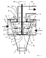
- a representative example of the centrifugal classifiers in Figs. 1 and 2 comprises a casing k whose lower part is formed into a cone-shaped hopper h, an air inlet 7 provided in the tangental direction to a cylindrical part of the casing, a fine powder outlet 8 mounted to the top of the casing, a rotor rotational shaft 10 mounted to the almost center in the cylindrical part of the casing for rotating by means of a motor M, a rotational plate 11 fixed to the rotational shaft 10, a dispersion plate 2 mounted to a place where a powder raw material 3 falls from the powder inlet 1, a plurality of rotor blades 5 whose one ends are fixed to the rotational plate 11 and whose other ends are fixed to the dispersion plate 2, a partition plate 9 mounted to the rotor blades 5 for partitioning a classification chamber defined between the dispersion plate 2 and the rotational plate 11 into a plurality of storeys and guide vanes 4 provided in the casing k so as to be opposed to the
- the structures and effects of the centrifugal air classifiers in Figs. 1 and 2 are basically the same except for a point that the cylindrical rotor, namely, the rotational plate 11 and the dispersion plate 2 are formed to be the same in diameter and the guide vanes 4 and the rotor blades 5 are provided parallel to the rotor rotational shaft 10 (in vertical direction) in the classifier in Fig. 1 while the truncated cone-shaped rotor, namely, the rotational plate 11 is formed to be smaller in diameter than the dispersion plate 2 and the rotor blades 5 and the guide vanes 4 are inclined at angles of inclination ⁇ 1 and ⁇ 2 with respect to the rotor rotational shaft 10 in the classifier in Fig. 2 .
- the angles of inclination ⁇ 1 and ⁇ 2 are suitably selected in a range of 0 to 40 degrees, for example.
- air for classification In a conventional common sense, it has been known as a fact that, in a same classifier, decrease in flow rate of the air or gas to be used in classification (hereinafter referred to as "air for classification") causes great deterioration in accuracy in classification and ratio of collection of products.
- the result of analysis means that the rotational speed of the rotor and the component of the velocity of the air for classification inward in a radial direction of the rotor should not be decreased in order to maintain the accuracy in classification and the ratio of collection. Many designers seem to have almost got hold of proper values by experience to put them into practice.
- the inventor of the present invention paid attention to the height of the rotor.
- improvement in accuracy of classification and ratio of collection there is not any established quantitative theory with respect to the height but only two opposite qualitative opinions.
- the first opinion is that "the height of the rotor should be sufficiently high in order to give all particles enough opportunities of classification”.
- the second opinion is that "the height of the rotor should be low in order to quickly complete classification for the purpose of preventing an unnecessary size of particles from being mixed in the classification".
- Fig. 3 shows the first opinion as a simplified imaginary illustration.
- the signs and numerals of the same as those in Figs. 1 and 2 have the same names and functions.
- the powder raw material 3 supplied from the powder inlet 1 onto the dispersion plate 2 enters into the classification space 12 defined between the guide vanes 4 and the rotating rotor blades 5 and is subject to classification in accordance with the balance between the centrifugal force and resistance force that acts on the particles during the fall in the space 12.
- the balance is determined according to the rotational speed of the rotor 6 and the flow rate of the air for classification supplied from the air inlet 7.
- a small particle B which enters inside the rotor blades 5 with the air for classification A is to be discharged from the fine powder outlet 8 and a fine powder (a minute powder) B is sorted and caught for collection in a dust collector (not shown in the drawings).
- a large particle(a coarse powder) C I which falls in the classification space 12 is to be collected in a cone part (not shown in Fig. 3 ) provided at a lower place.
- the classification requires time on the basis of movement of the particles and it takes further longer time to separate(disperse) the fine powder B adhered to the large particle C, as shown in Fig. 3 .
- the above time and the time for a group of particles to fall are calculated accurately, it allows a proper value of the height of the rotor to be calculated.
- Fig. 4 shows an example of a widely sold classifier in which the second opinion is put into practice and the height of the rotor is made extremely low.
- the signs and numerals of the same as those in the previously-mentioned drawings have the same names and functions.
- 15 denotes a classification rotor
- 16 denotes air and a raw material
- 17 denotes a dispersion blade
- 19 denotes a classification blade
- 20 denotes a coarse powder outlet
- 21 denotes air
- 22 denotes a spiral casing
- 23 denotes a balance rotor overlapping with the classification rotor
- 24 denotes a supporting pedestal
- 25 denotes a rotor rotational shaft.
- the method is to select a centrifugal air classifier, which has been used for a long time, 15 years or more, for example, as a classifier in actual operation in a cement field or the like, to examine abrasion of the rotor blades.
- the powder raw material supplied from the upper part undergoes a classification operation
- a diameter of a particle which is on a border between the side of fine powder B (entering inside the rotor with air to be discharged) and the side of the coarse powder C (falling downward to be discharged)
- the classification operation on a powder is actually carried out at the tops of the rotor blades 5 (the outer circumferential part of the arranged rotor blades 5), so that the abrasion of the tops of the rotor blades 5 must advance as long as the operation is carried out.
- the abrasion in examination of a state of the abrasion of the tops of the rotor blades 5 in a direction of the height of the rotor, the abrasion must have been advanced at the upper part, of course, while the lower part not abraded at all means that the part has not undergone classification operation, namely, is redundant for the classifier, and therefore, it can be said that such lower part is omissible.
- Fig. 5 shows a state of abrasion of rotor blades of the classifier which has been used for 15 years or more in actual operation of three kinds A (in Fig. 5A ), B (in Fig. 5B ) and C (in Fig. 5C ) different in size and processing quantity from each other.
- the measured abrasion depth d is shallow as much as 2 mm at the maximum. In Fig. 5 , only the abrasion depth is shown in enlarged dimension for the purpose of easy understanding.
- the rotor blade 5 is provided between the dispersion plate 2 and the rotation disc 11 and partitioned into a plurality of storeys by means of the horizontal annular partition plate 9.
- An abrasion part m of the rotor blade 5 decreases from the upper part 5a toward the lower part 5b and abrasion is not detected at the lower part 5b. It can be considered that abrasion of a part just below the horizontal partition plate 9 is little because there is an area where powder scarcely exists since the powder falling from the vicinity of a tip end 9a of the partition plate 9 receives the classification operation to go to the tip end of the rotor blade 5 (the fine powder further goes to the inside of the rotor during the fall in the vertical direction due to gravity).
- a point (a border point) CP at which the abrasion depth d was assumed to be zero when the deepest points of the abrasion depth d were connected by means of a line T as shown in Fig. 5 in order to specify a border between a part undergoing the classification operation and a part not undergoing the operation in the direction of the height of the tip end of the rotor blade 5.
- the inventor of the present invention studied what relation the point CP has with the capacity of a classifier (the size of a classifier based on the processing quantity). As a result, the following method was found.
- S1 and S2 will be described with reference to Figs. 2 , 5 and 6 .
- the signs and numerals of the same as those in the previously-mentioned drawings have the same names and functions.
- S1 is an area of a side surface of a cylinder (or a truncated cone) circumscribed about the rotor blades 5, an axis of the cylinder being the rotor rotational shaft 10, (the side area of the rotor) (m 2 ).
- the S1 (the side area of the rotor) can be calculated by: ⁇ H ⁇ ⁇ D ⁇ 1 + D ⁇ 2 / 2 , wherein H' denotes a height (m) of the rotor blade 5 from the dispersion plate to the point CP in the vertical direction and (D1 + D2) / 2 denotes an average value (m) in calculation of a diameter of a circle crossing with the rotor rotational shaft at right angles and circumscribed about the rotor blade, the diameter.
- D1 denotes a diameter (m) of a circle circumscribed about the rotor blades 5 at the upper end portion thereof while D2 denotes a diameter (m) of a circle circumscribed about the rotor blades at the point CP.
- S2 denotes a cross sectional area (m 2 ) of inflow of the air for classification.
- the S2 (the cross sectional area of inflow of the air for classification) is calculated by: the S1 - (the cross sectional area SB of the rotor blade + the cross sectional area SH of the partition plate 9) + the area SY of an overlapping part between the rotor blades and the partition plate 9.
- the cross sectional area SB is a cross sectional area (m 2 ) between the dispersion plate of the rotor blade and the point CP.
- the SB can be obtained by tB ⁇ H' ⁇ nB.
- the sign tB denotes a thickness (m) of the rotor blade 5 and nB denotes the total number of the rotor blades, respectively.
- the cross sectional area SH can be obtained by ⁇ DH ⁇ tH ⁇ nH.
- DH denotes a diameter (m) of the partition plate 9
- tH denotes a thickness of the partition plate 9
- nH denotes the total number of the partition plates 9 existing between the dispersion plate and the point CP, respectively.
- the area SY of the overlapping part between the rotor blades and the partition plate can be obtained by tB ⁇ tH ⁇ nBV ⁇ nH.
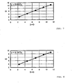
- the straight-line relation of the S1 or S2 and the D 2 in Figs. 7 and 8 means that a ratio of S1 and D 2 or a ratio of S2 and D 2 is of a constant value of around 0.93 and 0.80, respectively, irrespective of the difference in capacity (size) of the classifier.
- (S1 / D 2 ) and (S2 / D 2 ) in Table 1 denote values similarly calculated with a conventional size of the rotor of the classifier (wherein H denotes a height of the rotor blade) without taking the position of the point CP into consideration.
- Designing the rotor and the rotor blades to be smaller than S1 and S2 has a sufficient probability of deterioration in accuracy in classification and ratio of collection of products.
- designing the above to be larger than S1 and S2 causes no problem of the accuracy in classification and the ratio of collection but causes increase in the amount of investment in plant and equipment and running costs.
- S2 may be determined arbitrarily within a range a little larger than the values shown in Figs. 7 and 8 in view of some safety.
- the above-mentioned point CP is a border point where abrasion of the tip end of the rotor blade is not detected, and therefore, in the lower part from the border, there is no guarantee that the classification operation does not exist although no large-scale classification occurs. Further, an effect of reduction in the amount of investment in plant and equipment and running costs becomes small when the height of the rotor and the rotor blade becomes high, that is, when the value of S2 / D 2 becomes large. On the other hand, deterioration in accuracy in classification and ratio of collection is likely to occur when the value of S2 / D 2 becomes too small.
- the inventor of the present invention carried out an experiment that, with the classifier having two powder inlets and provided in a direction of 180° with respect to the rotor rotation shaft, one powder inlet was closed while the whole quantity of the raw material powder were supplied from the other inlet. This results in great deterioration in accuracy in classification and ratio of collection.
- the inventor of the present invention concluded that the reason of the above was that the powder supplied to the classifier entered from the outer circumferential part of the dispersion plate in the upper part of the rotor into the classification space (between the guide vane and the rotor blades) to undergo a classification operation, and at that time, the concentration of the powder per a unit space was lower in the case that the powder entered evenly and as widely as possible from the whole outer circumference of the dispersion plate than the case that the powder entered intensively from any one place of the outer circumference part of the dispersion plate, and thereby, the dispersion of the powder was accelerated, so that the classification became close to the desirable one.
- setting the height of the rotor in accordance with the invention causes no deterioration in accuracy in classification and ratio of collection even in the case that an unvigorous classification that occurs below the point CP (the border point) is omitted, since properly providing the powder inlet causes improvement in accuracy in classification and ratio of collection.
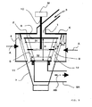
- most preferable is a method of providing the powder inlet at one place in an area including at the center thereof the rotor rotational shaft 10 as shown in Fig. 9 from the viewpoint of even dispersion of a powder over the whole outer circumference of the upper part of the rotor 6.
- the method has a disadvantage that the powder raw material 3 goes to the outer circumference of the upper part of the rotor 6 at a low speed, and thereby, the powder raw material cannot be supplied at a comparatively high speed since the centrifugal force operates little on the supplied powder raw material 3 in the vicinity of the rotor rotational shaft 10 of the dispersion plate 2.
- one or plural square powder inlet 1 is provided in a place not including rotor rotational shaft 10 and the sum (for all powder inlets) ⁇ F of interior angles ⁇ i and ⁇ j and interior angles of ⁇ k and ⁇ n respectively formed from two lines of L1 and L2 and two lines of L3 and L4, which extend from the rotor rotational shaft 10 so as to circumscribe about horizontal cross sections of the respective powder inlets 1 and which are vertical to the rotor rotational shaft 10, is set at 90° or more, 90 ⁇ ° ⁇ ⁇ F ⁇ 360 ⁇ ° , for example, as shown in Fig. 10 .
- the powder inlets in the above case are preferably provided as even as possible over the whole circumference without being biased in the circumferential direction.
- the shape of the powder raw material inlet 1 is not limited to a square shape.
- the shape and size of the inlet 1 is properly selected in accordance with necessity.
- the length w of projection of the top 9a of the partition plate 9 from the top 5S of the rotor blade 5 is preferably as small as possible for the purpose of achieving the effective classification operation in a whole area in the direction of the height of the top of the rotor blade.
- the length w of the projection is preferably set at 0 to 7 mm, for example, and more preferably, 2 to 5 mm so that the top 5S of the rotor blade 5 and the top 9a of the partition plate 9 would be located in a substantially same plane.
- the above-mentioned countermeasures allow a centrifugal air classifier not using unnecessarily voluminous air (air or gas) for classification to be designed. Also, it becomes dispensable to provide an unnecessarily large fan or a blower, which is provided additionally, and an unnecessarily large bag filter used as a dust collector.
- the flow rate of air or gas which is determined as described above, also has an influence on the size of the rotor per se.
- the air for classification flowing into the rotor through the guide vanes is required to transport in the form of an air flow including dust the whole quantity of the powder, which is classified into the fine powder side, to a dust collector via the rotor, the fine powder outlet and a duct connected thereafter. Therefore, the rotor and the vicinity thereof should be designed so that a component in a vertical direction of the velocity of the air or gas at the top part of the rotor should be 12 m/s or more, and preferably, 16 to 22 m/s when the air or gas goes to the duct connected to an upper part of the rotor in the rotor.
- the present invention provides a method of designing a centrifugal air classifier comprising: a rotor provided in a casing and including a dispersion plate and a rotational plate, the plates being fixed to a rotor rotational shaft with a space therebetween in an axial direction, and a plurality of rotor blades held between outer circumferential parts of the both plates; guide vanes provided outside the rotor blades so as to be opposed to the rotor blades through a classification space; an air inlet provided in the casing for supplying the classification space with air for classification through the guide vanes; a powder inlet provided in an upper part of the casing so as to be faced to the dispersion plate; and a fine powder outlet for discharging a classified fine powder to the outside of the classifier, wherein the method comprises the
- the powder inlet in accordance with the invention may be provided in a place including the rotor rotational shaft.
- the powder inlet in accordance with the invention may be provided in one or plural number in a place not including the rotor rotational shaft, and a sum ⁇ F of interior angles formed from two lines extending from the rotor rotational shaft as to the centrifugal air classifier according to any one of Claims 1, 2, 3, and 4, wherein the powder inlet is provided in one place including the rotor rotational shaft, may be 90° ⁇ ⁇ F ⁇ 360°.
- the rotor blades may be partitioned into a plurality of storeys by means of horizontal annular partition plates and the tip end of the partition plate may be located in a substantially same plane as the tip end of the rotor blade.
- the tip end of the partition plate may be projected by 0 to 7 mm from the tip end of the rotor blade.
- a centrifugal air classifier shown in Figs. 1 and 2 is a typical classifier having been conventionally used and being in actual operation in world cement plants widely.
- the classifier comprises a casing k whose lower part is formed into a cone-shaped hopper h, an air inlet 7 provided in the tangent direction to a cylindrical part of the casing, a fine powder outlet 8 mounted to the top of the casing, a rotor rotational shaft 10 mounted to the almost center in the cylindrical part of the casing, a rotational plate 11 mounted to the rotational shaft 10, a dispersion plate 2 mounted to a place where a powder raw material 3 falls from the powder inlet 1, a plurality of rotor blades 5 whose one ends are fixed to the rotational plate 11 and whose other ends are fixed to the dispersion plate 2, a horizontal partition plate 9 mounted to the rotor blades 5 for partitioning a classification chamber formed between the dispersion plate 2 and the rotational plate 11 into a plurality of storeys and guide blades
- the powder raw material 3 thrown from the powder inlet 1 falls onto the dispersion plate 2 of the rotating rotor 6 to be dispersed and scattered in the horizontal direction, has a collision with a collision plate 13 to be dispersed (or crushed), and then, falls in the classification space 12.
- air (air or gas) for classification A has been supplied from the air inlet 7 to flow into the classification space 12 through the guide vanes 4.
- the velocity of the air for classification A has a component toward the center of the rotor 6 to form a vortex air flow.
- the air for classification A is accelerated to the velocity necessary for classification by means of the rotor blade 5.
- the particle (powder raw material) 3 supplied to the classification space 12 starts a gyrating movement together with the air for classification A. At that time, classification is performed in accordance with the balance between the centrifugal force and resistance force, which operate on the grain.
- a particle (coarse powder) C having a diameter larger than that of the cut-off size of particles is repeatedly classification-operated to sink due to gravity and discharged from the lower part of the hopper h. Incidentally, the diameter of the cut-off size of particles is adjusted in accordance with the rotational speed of the rotor 6.
- the inventor of the present invention altered the centrifugal air classifier on the basis of the present invention to examine the flow rate of air, the accuracy of the classifier and a ratio of collection (evaluated by "quantity of crush” since a closed circuit crushing process connected to a crusher is applied in Embodiment 1), and obtained a result shown in Table 2.
- the setting was same in both of the cases of ordinary cement and high-early-strength cement.
- Embodiment 2 shows a case that a comparatively large-sized classifier according to the present invention is newly provided instead of alteration.
- a centrifugal air classifier of the same kind as that of Embodiment 1 is redesigned on the basis of the invention.
- used is a centrifugal classifier of the same kind as that of Embodiment 1, the classifier having the same production scale and being in operation adjacently in the same cement plant, wherein the technique of the invention is not applied to the classifier.
- Table 3 The data is shown in Table 3.
- the quantity of air used for classification was reduced by around 30 %, compared with the same kind of classifier having conventional specifications, which was used as the subject, (it was 3000 m 3 /min in the subject for comparison while it was 2100 m 3 /min in the invention), but both of the accuracy in classification (the 30 ⁇ m residue, the 45 ⁇ m residue and the ratio of division ⁇ in this case) and the ratio of collection (the crush quantity in this case) were of better values than those of the subject for comparison, similarly to Embodiment 1. That is to say, both of the accuracy in classification and the ratio of collection were good in performance although the flow rate of the air for classification was decreased by 30 % in the present invention.
- the present invention is applied to facilities such as a cement manufacturing plant since classification can be performed at the predetermined accuracy and ratio of collection with the minimum necessary flow rate of air for classification.
- the air for classification includes gas other than air, as described above.
Landscapes
- Combined Means For Separation Of Solids (AREA)
Claims (6)
- Verfahren zum Konstruieren eines Zentrifugalwindsichters mit einem Rotor (6) in einem Gehäuse (k) und einschließlich einer Streuplatte (2) und einer Drehplatte (11), wobei die Platten (2, 11) axial beabstandet an einer drehbaren Rotorwelle (10) befestigt sind, sowie mit einer Vielzahl von Rotorblättern (5), die zwischen Außenumfangsteilen beider Platten (2, 11) gehaltert sind; mit Führungsflügeln (4) außerhalb der Rotorblätter (5), die den Rotorblättern (5) über einen Klassierraum (12) gegenüber liegen; mit einem Luftzulauf (7) im Gehäuse (k) zur Zufuhr von Luft zum Klassierraum (12) durch die Führungsflügel (4) hindurch; mit einem der Streuplatte (2) zugewandten Pulvereinlass (1) in einem Oberteil des Gehäuses (k); und mit einem Feinpulverauslass (8) zum Austragen eines klassierten Feinpulvers zur Außenseite des Sichters, dadurch gekennzeichnet, dass das Verfahren folgenden Schritt aufweist:(a) Berechnen der optimalen Rotorhöhe unter Verwendung einer Beziehung S2/D2 = 0,8 bis 1,4 zwischen der Querschnittsfläche S2 des Querschnitts des Klassierluftzulaufs und einem rechnerischen Mittelwert D eines Durchmessers eines Kreises, der orthogonal zur Rotordrehwelle liegt und die Rotorblätter umschreibt.
- Verfahren nach Anspruch 1, bei dem im Schritt (a) die Beziehung S2/D2 = 0,9 bis 1,3 gilt.
- Verfahren nach einem der Ansprüche 1 oder 2, bei dem der Pulvereinlass (1) an einer Stelle einschließlich der Rotordrehwelle (10) vorgesehen ist.
- Verfahren nach einem der Ansprüche 1 oder 2, bei dem ein oder mehrere Pulvereinlässe (1) an die Rotordrehwelle (10) nicht einschließenden Stellen vorgesehen sind, und
wobei für eine Summe θF der Innenwinkel von zwei Geraden, die von der Rotordrehwelle (10) ausgehend die waagerechten Querschnitte der zugehörigen Pulvereinlässe (1) umschreiben und die zugehörigen Pulvereinlässe (1) einschließen und die vertikal zur Rotordrehwelle (10) verlaufen, die Beziehung 90° ≤ θF ≤ 360° gilt. - Verfahren nach einem der Ansprüche 1 oder 2, bei dem die Rotorblätter (5) mittels horizontaler ringförmiger Trennplatten (9) zu mehreren Etagen aufgeteilt sind und die Spitze (9a) der Trennplatte (9) in im Wesentlichen der gleichen Ebene liegt wie die Spitze der Rotorblatts (5).
- Verfahren nach Anspruch 5, bei dem die Spitze (9a) der Trennplatte (9) 0 mm bis 7 mm weit über die Spitze des Rotorblatts hinausragt.
Applications Claiming Priority (1)
| Application Number | Priority Date | Filing Date | Title |
|---|---|---|---|
| PCT/JP2006/304033 WO2007097042A1 (ja) | 2006-02-24 | 2006-02-24 | 遠心式空気分級機 |
Publications (3)
| Publication Number | Publication Date |
|---|---|
| EP1992422A1 EP1992422A1 (de) | 2008-11-19 |
| EP1992422A4 EP1992422A4 (de) | 2011-11-02 |
| EP1992422B1 true EP1992422B1 (de) | 2013-09-18 |
Family
ID=38437101
Family Applications (1)
| Application Number | Title | Priority Date | Filing Date |
|---|---|---|---|
| EP06728595.7A Expired - Lifetime EP1992422B1 (de) | 2006-02-24 | 2006-02-24 | Verfahren zum gestalten eines zentrifugalwindsichters |
Country Status (8)
| Country | Link |
|---|---|
| US (1) | US8353408B2 (de) |
| EP (1) | EP1992422B1 (de) |
| JP (1) | JP5048646B2 (de) |
| KR (1) | KR101223391B1 (de) |
| CN (1) | CN101370600B (de) |
| CA (1) | CA2642489C (de) |
| DK (1) | DK1992422T3 (de) |
| WO (1) | WO2007097042A1 (de) |
Cited By (1)
| Publication number | Priority date | Publication date | Assignee | Title |
|---|---|---|---|---|
| CN106999946A (zh) * | 2014-12-16 | 2017-08-01 | 三菱日立电力系统株式会社 | 旋转式分级机以及立式粉碎机 |
Families Citing this family (26)
| Publication number | Priority date | Publication date | Assignee | Title |
|---|---|---|---|---|
| DE102008038776B4 (de) * | 2008-08-12 | 2016-07-07 | Loesche Gmbh | Verfahren zur Sichtung eines Mahlgut-Fluid-Gemisches und Mühlensichter |
| EP2569069B1 (de) * | 2010-05-10 | 2019-04-10 | Thermo Fisher Scientific Inc. | Partikelmaterialmonitor |
| EP2505272B1 (de) * | 2011-03-30 | 2014-06-04 | Bayer Intellectual Property GmbH | Mobiler Sichter |
| FR2976194B1 (fr) * | 2011-06-08 | 2014-01-10 | Pa Technologies | Separateur dynamique pour materiaux pulverulents |
| US9254508B2 (en) * | 2011-09-29 | 2016-02-09 | Kashiwabara Corporation | Powder and granular material separation processing device, powder and granular material separation processing method, and powder and granular material separation and collection processing system |
| JP5795253B2 (ja) * | 2011-12-27 | 2015-10-14 | 株式会社アーステクニカ | 分級機 |
| US8813967B2 (en) * | 2012-05-02 | 2014-08-26 | Alstom Technology Ltd | Adjustable mill classifier |
| JP6009349B2 (ja) * | 2012-12-27 | 2016-10-19 | 株式会社アーステクニカ | 分級機構および分級方法 |
| DE102013101517A1 (de) * | 2013-02-15 | 2014-08-21 | Thyssenkrupp Resource Technologies Gmbh | Sichter und Verfahren zum Betreiben eines Sichters |
| CN103878075A (zh) * | 2014-03-24 | 2014-06-25 | 卢海泉 | 一种利用粉煤灰生产硅铝合金粉的设备 |
| JP6328229B2 (ja) * | 2014-03-31 | 2018-05-23 | ホソカワミクロン株式会社 | 分級機 |
| CN104028462A (zh) * | 2014-06-10 | 2014-09-10 | 武汉天沭除尘设备有限公司 | 一种用于超细粉体选粉的分级式选粉机 |
| KR101530008B1 (ko) * | 2014-10-30 | 2015-06-19 | 제이에스테크 주식회사 | 원심 분급기 |
| CN104607393B (zh) * | 2014-12-14 | 2018-10-09 | 北京化工大学 | 涡流空气分级机倾斜式导流装置 |
| DE102016015051B4 (de) * | 2016-12-16 | 2019-01-31 | Hosokawa Alpine Aktiengesellschaft | Sichtrad für einen Zentrifugalkraft-Windsichter |
| CN107511248A (zh) * | 2017-08-25 | 2017-12-26 | 长沙深湘通用机器有限公司 | 粉碎和单机分选多产品的工艺方法 |
| JP7136192B2 (ja) * | 2018-03-30 | 2022-09-13 | 日本ゼオン株式会社 | 分離回収方法 |
| CN108927332A (zh) * | 2018-08-15 | 2018-12-04 | 山东达利尔重工股份有限公司 | 粉体干法立式分级叶轮 |
| DE102018008127B4 (de) | 2018-10-13 | 2022-06-09 | Hosokawa Alpine Aktiengesellschaft | Blaskopf und Verfahren zur Herstellung einer Mehrschichtschlauchfolie |
| DE102018009632B4 (de) | 2018-12-11 | 2021-12-09 | Hosokawa Alpine Aktiengesellschaft | Vorrichtung zum Aufwickeln und Wickelwechsel von bahnförmigem Material und ein Verfahren dafür |
| DE102020000334A1 (de) | 2020-01-21 | 2021-07-22 | Hosokawa Alpine Aktiengesellschaft | Vorrichtung und Verfahren zur monaxialen Längenänderung von Folienbahnen |
| KR102427333B1 (ko) * | 2020-12-11 | 2022-08-02 | (주) 태흥산업 | 원심 분급기 |
| KR102910625B1 (ko) * | 2021-10-19 | 2026-01-09 | 주식회사 엘지화학 | 분체 유량 분배기 및 이를 이용한 분체 유량 분배 방법 |
| CN114192272B (zh) * | 2021-11-05 | 2024-07-12 | 江苏大学 | 一种应用于尾矿回收的流量自调节式矿径分级装置 |
| GB2617458A (en) * | 2021-11-05 | 2023-10-11 | Univ Jiangsu | Flow self-regulating ore diameter classification device applied to tailings recovery |
| DE102022000351A1 (de) | 2022-01-29 | 2023-08-03 | Hosokawa Alpine Aktiengesellschaft | Verfahren und Vorrichtung zur Foliendickenregelung von gereckter im Folienblasverfahren hergestellter Schlauchfolie |
Family Cites Families (34)
| Publication number | Priority date | Publication date | Assignee | Title |
|---|---|---|---|---|
| US2587609A (en) * | 1947-06-05 | 1952-03-04 | Andrew J Fisher | Impact pulverizing apparatus having fluid jets firing toward a common point |
| JPS5615876A (en) | 1979-07-17 | 1981-02-16 | Onoda Cement Co Ltd | Classifier |
| JPS5615875A (en) | 1979-07-17 | 1981-02-16 | Onoda Cement Co Ltd | Classifier |
| JPS5724188A (en) | 1980-07-19 | 1982-02-08 | Oki Electric Ind Co Ltd | Correction circuit for pulse distortion |
| JPS5724189A (en) | 1980-07-21 | 1982-02-08 | Nec Corp | Scatter control system for automatic exchanger |
| US4390419A (en) * | 1981-10-16 | 1983-06-28 | Omya Gmbh | Centrifugal classifier |
| DE3425101A1 (de) * | 1984-07-07 | 1986-01-16 | Heinz 4630 Bochum Jäger | Verfahren und sichter zur trennscharfen sichtung eines gutstromes, insbesondere von zement |
| US4750677A (en) * | 1985-07-19 | 1988-06-14 | Taylor David W | Classifier for comminution of pulverulent material by fluid energy |
| GB8518536D0 (en) * | 1985-07-23 | 1985-08-29 | Smidth & Co As F L | Separator |
| US4721258A (en) * | 1985-12-12 | 1988-01-26 | The Babcock & Wilcox Company | Roll-and-race pulverizer with rotating throat |
| JP2571126B2 (ja) * | 1989-05-18 | 1997-01-16 | 秩父小野田株式会社 | 微粉用空気分級機 |
| US5215491A (en) * | 1992-02-07 | 1993-06-01 | Mattel, Inc. | Water actuated toy kitchen set |
| JP3482504B2 (ja) * | 1993-12-28 | 2003-12-22 | 太平洋セメント株式会社 | 空気分級装置 |
| WO1994022599A1 (fr) * | 1993-03-31 | 1994-10-13 | Onoda Cement Co., Ltd. | Separateur a air a tourbillon |
| JP3448716B2 (ja) * | 1993-12-28 | 2003-09-22 | 太平洋セメント株式会社 | 渦流式空気分級機 |
| CN2147900Y (zh) * | 1993-05-15 | 1993-12-01 | 王宝芬 | 超音速气流超微细粉碎分级机 |
| JPH08173909A (ja) * | 1994-12-22 | 1996-07-09 | Chichibu Onoda Cement Corp | 分級装置 |
| CN2214850Y (zh) * | 1995-03-01 | 1995-12-13 | 核工业理化工程研究院 | 面粉分级机 |
| FR2741286B1 (fr) * | 1995-11-21 | 1998-01-23 | Fcb | Separateur a air a action centrifuge |
| JP3517692B2 (ja) * | 1996-01-12 | 2004-04-12 | 株式会社リコー | 気流式分級装置 |
| JPH09192606A (ja) * | 1996-01-23 | 1997-07-29 | Ishikawajima Harima Heavy Ind Co Ltd | 回転式分級機 |
| US5957300A (en) * | 1996-01-29 | 1999-09-28 | Sure Alloy Steel Corporation | Classifier vane for coal mills |
| JP3884826B2 (ja) * | 1996-07-30 | 2007-02-21 | キヤノン株式会社 | 固体粒子の表面の処理装置、固体粒子の表面の処理方法及びトナーの製造方法 |
| DE19743490A1 (de) * | 1996-10-04 | 1998-04-16 | Schmidt & Co Gmbh & Co Kg | Windsichter |
| US6276534B1 (en) * | 1998-04-03 | 2001-08-21 | Hosokawa Micron Powder Systems | Classifier apparatus for particulate matter/powder classifier |
| DE19908334A1 (de) * | 1999-02-26 | 2000-08-31 | Heinz Jaeger | Windsichter |
| CN2359011Y (zh) * | 1999-03-05 | 2000-01-19 | 蔡塔 | 高效复合离心式选粉机 |
| JP2001104888A (ja) * | 1999-10-06 | 2001-04-17 | Hosokawa Micron Corp | 分級機 |
| JP3477437B2 (ja) * | 2000-10-13 | 2003-12-10 | 川崎重工業株式会社 | 気流式分級機 |
| JP4026051B2 (ja) * | 2002-02-21 | 2007-12-26 | ホソカワミクロン株式会社 | 分級機 |
| NO321643B1 (no) * | 2004-05-18 | 2006-06-19 | Comex As | Partikkelseparator |
| CN2745663Y (zh) * | 2004-10-28 | 2005-12-14 | 贵阳铝镁设计研究院 | 高效离心式选料机 |
| DE102006044833B4 (de) * | 2006-09-20 | 2010-01-21 | Babcock Borsig Service Gmbh | Zentrifugalsichter und Verfahren zum Sichten |
| DE102006048865A1 (de) * | 2006-10-16 | 2008-04-17 | Roland Dr. Nied | Verfahren zur Erzeugung feinster Partikel und Strahlmühle dafür sowie Windsichter und Betriebsverfahren davon |
-
2006
- 2006-02-24 CA CA2642489A patent/CA2642489C/en not_active Expired - Lifetime
- 2006-02-24 DK DK06728595.7T patent/DK1992422T3/da active
- 2006-02-24 KR KR1020087019545A patent/KR101223391B1/ko not_active Expired - Fee Related
- 2006-02-24 EP EP06728595.7A patent/EP1992422B1/de not_active Expired - Lifetime
- 2006-02-24 CN CN2006800527297A patent/CN101370600B/zh not_active Expired - Fee Related
- 2006-02-24 US US12/280,122 patent/US8353408B2/en not_active Expired - Fee Related
- 2006-02-24 JP JP2008501592A patent/JP5048646B2/ja not_active Expired - Fee Related
- 2006-02-24 WO PCT/JP2006/304033 patent/WO2007097042A1/ja not_active Ceased
Cited By (1)
| Publication number | Priority date | Publication date | Assignee | Title |
|---|---|---|---|---|
| CN106999946A (zh) * | 2014-12-16 | 2017-08-01 | 三菱日立电力系统株式会社 | 旋转式分级机以及立式粉碎机 |
Also Published As
| Publication number | Publication date |
|---|---|
| US8353408B2 (en) | 2013-01-15 |
| EP1992422A4 (de) | 2011-11-02 |
| CA2642489A1 (en) | 2007-08-30 |
| KR101223391B1 (ko) | 2013-01-16 |
| CA2642489C (en) | 2013-10-08 |
| JP5048646B2 (ja) | 2012-10-17 |
| KR20080113200A (ko) | 2008-12-29 |
| JPWO2007097042A1 (ja) | 2009-07-09 |
| WO2007097042A1 (ja) | 2007-08-30 |
| EP1992422A1 (de) | 2008-11-19 |
| CN101370600A (zh) | 2009-02-18 |
| DK1992422T3 (da) | 2013-12-16 |
| US20090065403A1 (en) | 2009-03-12 |
| CN101370600B (zh) | 2011-10-05 |
Similar Documents
| Publication | Publication Date | Title |
|---|---|---|
| EP1992422A1 (de) | Zentrifugalwindsichter | |
| JP3800556B2 (ja) | アトリションミル及びスラリー内の粒子選別方法 | |
| US5094391A (en) | Pneumatic classifier | |
| KR20190077387A (ko) | 분리기 및 분리기를 구비한 분쇄기 | |
| JP2792576B2 (ja) | 竪型粉砕機 | |
| JP2002119920A (ja) | 気流式分級機 | |
| CN109590215B (zh) | 多级颗粒分选机 | |
| CN101961713B (zh) | 无转子分级机 | |
| Ji et al. | Numerical study on the influence mechanism of feed rate on separation quality in a multi-baffle separation duct | |
| JPS60232257A (ja) | 竪型ロ−ラミル | |
| RU212205U1 (ru) | Ударно-инерционный измельчитель рудных масс с возвратным лифтером | |
| JPH04281858A (ja) | 粉砕装置 | |
| JP2664061B2 (ja) | 空気分級機 | |
| JPS63214383A (ja) | 分級装置 | |
| CN201216997Y (zh) | 超微气流分级机 | |
| JP3329043B2 (ja) | 分級装置 | |
| KR102805664B1 (ko) | 분리기, 밀 및 기체-고체 혼합물을 분리하기 위한 방법 | |
| Weigel et al. | Development of an air classifier for the classification of crushed aggregates | |
| JP2545322Y2 (ja) | 三方向分級機 | |
| CN115945306A (zh) | 卧式高效旋风粉体颗粒多段分级分离器 | |
| JPS62176556A (ja) | 竪型粉砕機の粉粒体分級装置 | |
| CN106999946A (zh) | 旋转式分级机以及立式粉碎机 | |
| SU1162511A1 (ru) | Сепаратор дл разделени порошкообразных материалов | |
| JPS61178044A (ja) | 竪型粉砕機 | |
| JPH0549077U (ja) | 三方向分級機 |
Legal Events
| Date | Code | Title | Description |
|---|---|---|---|
| PUAI | Public reference made under article 153(3) epc to a published international application that has entered the european phase |
Free format text: ORIGINAL CODE: 0009012 |
|
| 17P | Request for examination filed |
Effective date: 20080923 |
|
| AK | Designated contracting states |
Kind code of ref document: A1 Designated state(s): AT BE BG CH CY CZ DE DK EE ES FI FR GB GR HU IE IS IT LI LT LU LV MC NL PL PT RO SE SI SK TR |
|
| A4 | Supplementary search report drawn up and despatched |
Effective date: 20111005 |
|
| RIC1 | Information provided on ipc code assigned before grant |
Ipc: B07B 7/083 20060101AFI20110928BHEP |
|
| 17Q | First examination report despatched |
Effective date: 20120524 |
|
| DAX | Request for extension of the european patent (deleted) | ||
| GRAP | Despatch of communication of intention to grant a patent |
Free format text: ORIGINAL CODE: EPIDOSNIGR1 |
|
| INTG | Intention to grant announced |
Effective date: 20130411 |
|
| RAP1 | Party data changed (applicant data changed or rights of an application transferred) |
Owner name: TAIHEIYO CEMENT CORPORATION |
|
| GRAS | Grant fee paid |
Free format text: ORIGINAL CODE: EPIDOSNIGR3 |
|
| GRAA | (expected) grant |
Free format text: ORIGINAL CODE: 0009210 |
|
| AK | Designated contracting states |
Kind code of ref document: B1 Designated state(s): AT BE BG CH CY CZ DE DK EE ES FI FR GB GR HU IE IS IT LI LT LU LV MC NL PL PT RO SE SI SK TR |
|
| REG | Reference to a national code |
Ref country code: GB Ref legal event code: FG4D |
|
| REG | Reference to a national code |
Ref country code: CH Ref legal event code: EP |
|
| REG | Reference to a national code |
Ref country code: IE Ref legal event code: FG4D |
|
| REG | Reference to a national code |
Ref country code: AT Ref legal event code: REF Ref document number: 632445 Country of ref document: AT Kind code of ref document: T Effective date: 20131015 |
|
| REG | Reference to a national code |
Ref country code: DE Ref legal event code: R096 Ref document number: 602006038468 Country of ref document: DE Effective date: 20131114 |
|
| REG | Reference to a national code |
Ref country code: DK Ref legal event code: T3 Effective date: 20131213 |
|
| REG | Reference to a national code |
Ref country code: RO Ref legal event code: EPE |
|
| PG25 | Lapsed in a contracting state [announced via postgrant information from national office to epo] |
Ref country code: CY Free format text: LAPSE BECAUSE OF FAILURE TO SUBMIT A TRANSLATION OF THE DESCRIPTION OR TO PAY THE FEE WITHIN THE PRESCRIBED TIME-LIMIT Effective date: 20130619 Ref country code: LT Free format text: LAPSE BECAUSE OF FAILURE TO SUBMIT A TRANSLATION OF THE DESCRIPTION OR TO PAY THE FEE WITHIN THE PRESCRIBED TIME-LIMIT Effective date: 20130918 Ref country code: SE Free format text: LAPSE BECAUSE OF FAILURE TO SUBMIT A TRANSLATION OF THE DESCRIPTION OR TO PAY THE FEE WITHIN THE PRESCRIBED TIME-LIMIT Effective date: 20130918 |
|
| REG | Reference to a national code |
Ref country code: NL Ref legal event code: VDEP Effective date: 20130918 |
|
| REG | Reference to a national code |
Ref country code: LT Ref legal event code: MG4D |
|
| PG25 | Lapsed in a contracting state [announced via postgrant information from national office to epo] |
Ref country code: GR Free format text: LAPSE BECAUSE OF FAILURE TO SUBMIT A TRANSLATION OF THE DESCRIPTION OR TO PAY THE FEE WITHIN THE PRESCRIBED TIME-LIMIT Effective date: 20131219 Ref country code: FI Free format text: LAPSE BECAUSE OF FAILURE TO SUBMIT A TRANSLATION OF THE DESCRIPTION OR TO PAY THE FEE WITHIN THE PRESCRIBED TIME-LIMIT Effective date: 20130918 Ref country code: LV Free format text: LAPSE BECAUSE OF FAILURE TO SUBMIT A TRANSLATION OF THE DESCRIPTION OR TO PAY THE FEE WITHIN THE PRESCRIBED TIME-LIMIT Effective date: 20130918 Ref country code: SI Free format text: LAPSE BECAUSE OF FAILURE TO SUBMIT A TRANSLATION OF THE DESCRIPTION OR TO PAY THE FEE WITHIN THE PRESCRIBED TIME-LIMIT Effective date: 20130918 |
|
| PG25 | Lapsed in a contracting state [announced via postgrant information from national office to epo] |
Ref country code: BE Free format text: LAPSE BECAUSE OF FAILURE TO SUBMIT A TRANSLATION OF THE DESCRIPTION OR TO PAY THE FEE WITHIN THE PRESCRIBED TIME-LIMIT Effective date: 20130918 Ref country code: CY Free format text: LAPSE BECAUSE OF FAILURE TO SUBMIT A TRANSLATION OF THE DESCRIPTION OR TO PAY THE FEE WITHIN THE PRESCRIBED TIME-LIMIT Effective date: 20130918 |
|
| PG25 | Lapsed in a contracting state [announced via postgrant information from national office to epo] |
Ref country code: NL Free format text: LAPSE BECAUSE OF FAILURE TO SUBMIT A TRANSLATION OF THE DESCRIPTION OR TO PAY THE FEE WITHIN THE PRESCRIBED TIME-LIMIT Effective date: 20130918 Ref country code: IS Free format text: LAPSE BECAUSE OF FAILURE TO SUBMIT A TRANSLATION OF THE DESCRIPTION OR TO PAY THE FEE WITHIN THE PRESCRIBED TIME-LIMIT Effective date: 20140118 Ref country code: SK Free format text: LAPSE BECAUSE OF FAILURE TO SUBMIT A TRANSLATION OF THE DESCRIPTION OR TO PAY THE FEE WITHIN THE PRESCRIBED TIME-LIMIT Effective date: 20130918 Ref country code: EE Free format text: LAPSE BECAUSE OF FAILURE TO SUBMIT A TRANSLATION OF THE DESCRIPTION OR TO PAY THE FEE WITHIN THE PRESCRIBED TIME-LIMIT Effective date: 20130918 Ref country code: CZ Free format text: LAPSE BECAUSE OF FAILURE TO SUBMIT A TRANSLATION OF THE DESCRIPTION OR TO PAY THE FEE WITHIN THE PRESCRIBED TIME-LIMIT Effective date: 20130918 |
|
| PG25 | Lapsed in a contracting state [announced via postgrant information from national office to epo] |
Ref country code: PL Free format text: LAPSE BECAUSE OF FAILURE TO SUBMIT A TRANSLATION OF THE DESCRIPTION OR TO PAY THE FEE WITHIN THE PRESCRIBED TIME-LIMIT Effective date: 20130918 Ref country code: ES Free format text: LAPSE BECAUSE OF FAILURE TO SUBMIT A TRANSLATION OF THE DESCRIPTION OR TO PAY THE FEE WITHIN THE PRESCRIBED TIME-LIMIT Effective date: 20130918 |
|
| REG | Reference to a national code |
Ref country code: DE Ref legal event code: R097 Ref document number: 602006038468 Country of ref document: DE |
|
| PG25 | Lapsed in a contracting state [announced via postgrant information from national office to epo] |
Ref country code: PT Free format text: LAPSE BECAUSE OF FAILURE TO SUBMIT A TRANSLATION OF THE DESCRIPTION OR TO PAY THE FEE WITHIN THE PRESCRIBED TIME-LIMIT Effective date: 20140120 |
|
| PLBE | No opposition filed within time limit |
Free format text: ORIGINAL CODE: 0009261 |
|
| STAA | Information on the status of an ep patent application or granted ep patent |
Free format text: STATUS: NO OPPOSITION FILED WITHIN TIME LIMIT |
|
| 26N | No opposition filed |
Effective date: 20140619 |
|
| PG25 | Lapsed in a contracting state [announced via postgrant information from national office to epo] |
Ref country code: IT Free format text: LAPSE BECAUSE OF FAILURE TO SUBMIT A TRANSLATION OF THE DESCRIPTION OR TO PAY THE FEE WITHIN THE PRESCRIBED TIME-LIMIT Effective date: 20130918 |
|
| PG25 | Lapsed in a contracting state [announced via postgrant information from national office to epo] |
Ref country code: LU Free format text: LAPSE BECAUSE OF FAILURE TO SUBMIT A TRANSLATION OF THE DESCRIPTION OR TO PAY THE FEE WITHIN THE PRESCRIBED TIME-LIMIT Effective date: 20140224 Ref country code: MC Free format text: LAPSE BECAUSE OF FAILURE TO SUBMIT A TRANSLATION OF THE DESCRIPTION OR TO PAY THE FEE WITHIN THE PRESCRIBED TIME-LIMIT Effective date: 20130918 |
|
| REG | Reference to a national code |
Ref country code: CH Ref legal event code: PL |
|
| REG | Reference to a national code |
Ref country code: DE Ref legal event code: R097 Ref document number: 602006038468 Country of ref document: DE Effective date: 20140619 |
|
| GBPC | Gb: european patent ceased through non-payment of renewal fee |
Effective date: 20140224 |
|
| PG25 | Lapsed in a contracting state [announced via postgrant information from national office to epo] |
Ref country code: CH Free format text: LAPSE BECAUSE OF NON-PAYMENT OF DUE FEES Effective date: 20140228 Ref country code: LI Free format text: LAPSE BECAUSE OF NON-PAYMENT OF DUE FEES Effective date: 20140228 |
|
| REG | Reference to a national code |
Ref country code: IE Ref legal event code: MM4A |
|
| PG25 | Lapsed in a contracting state [announced via postgrant information from national office to epo] |
Ref country code: IE Free format text: LAPSE BECAUSE OF NON-PAYMENT OF DUE FEES Effective date: 20140224 Ref country code: GB Free format text: LAPSE BECAUSE OF NON-PAYMENT OF DUE FEES Effective date: 20140224 |
|
| REG | Reference to a national code |
Ref country code: FR Ref legal event code: PLFP Year of fee payment: 11 |
|
| PG25 | Lapsed in a contracting state [announced via postgrant information from national office to epo] |
Ref country code: BG Free format text: LAPSE BECAUSE OF FAILURE TO SUBMIT A TRANSLATION OF THE DESCRIPTION OR TO PAY THE FEE WITHIN THE PRESCRIBED TIME-LIMIT Effective date: 20130918 |
|
| PG25 | Lapsed in a contracting state [announced via postgrant information from national office to epo] |
Ref country code: HU Free format text: LAPSE BECAUSE OF FAILURE TO SUBMIT A TRANSLATION OF THE DESCRIPTION OR TO PAY THE FEE WITHIN THE PRESCRIBED TIME-LIMIT; INVALID AB INITIO Effective date: 20060224 Ref country code: TR Free format text: LAPSE BECAUSE OF FAILURE TO SUBMIT A TRANSLATION OF THE DESCRIPTION OR TO PAY THE FEE WITHIN THE PRESCRIBED TIME-LIMIT Effective date: 20130918 |
|
| REG | Reference to a national code |
Ref country code: FR Ref legal event code: PLFP Year of fee payment: 12 |
|
| REG | Reference to a national code |
Ref country code: FR Ref legal event code: PLFP Year of fee payment: 13 |
|
| PGFP | Annual fee paid to national office [announced via postgrant information from national office to epo] |
Ref country code: DK Payment date: 20220209 Year of fee payment: 17 Ref country code: DE Payment date: 20211230 Year of fee payment: 17 Ref country code: AT Payment date: 20220125 Year of fee payment: 17 |
|
| PGFP | Annual fee paid to national office [announced via postgrant information from national office to epo] |
Ref country code: RO Payment date: 20220125 Year of fee payment: 17 Ref country code: FR Payment date: 20220118 Year of fee payment: 17 |
|
| REG | Reference to a national code |
Ref country code: DE Ref legal event code: R082 Ref document number: 602006038468 Country of ref document: DE Representative=s name: MEISSNER BOLTE PATENTANWAELTE RECHTSANWAELTE P, DE |
|
| REG | Reference to a national code |
Ref country code: DE Ref legal event code: R119 Ref document number: 602006038468 Country of ref document: DE |
|
| REG | Reference to a national code |
Ref country code: DK Ref legal event code: EBP Effective date: 20230228 |
|
| REG | Reference to a national code |
Ref country code: AT Ref legal event code: MM01 Ref document number: 632445 Country of ref document: AT Kind code of ref document: T Effective date: 20230224 |
|
| PG25 | Lapsed in a contracting state [announced via postgrant information from national office to epo] |
Ref country code: RO Free format text: LAPSE BECAUSE OF NON-PAYMENT OF DUE FEES Effective date: 20230224 Ref country code: AT Free format text: LAPSE BECAUSE OF NON-PAYMENT OF DUE FEES Effective date: 20230224 |
|
| PG25 | Lapsed in a contracting state [announced via postgrant information from national office to epo] |
Ref country code: FR Free format text: LAPSE BECAUSE OF NON-PAYMENT OF DUE FEES Effective date: 20230228 Ref country code: DK Free format text: LAPSE BECAUSE OF NON-PAYMENT OF DUE FEES Effective date: 20230228 Ref country code: DE Free format text: LAPSE BECAUSE OF NON-PAYMENT OF DUE FEES Effective date: 20230901 |