EP1992456A2 - Procédé et dispositif de manipulation d'objets flexibles en forme de tapis - Google Patents
Procédé et dispositif de manipulation d'objets flexibles en forme de tapis Download PDFInfo
- Publication number
- EP1992456A2 EP1992456A2 EP08008410A EP08008410A EP1992456A2 EP 1992456 A2 EP1992456 A2 EP 1992456A2 EP 08008410 A EP08008410 A EP 08008410A EP 08008410 A EP08008410 A EP 08008410A EP 1992456 A2 EP1992456 A2 EP 1992456A2
- Authority
- EP
- European Patent Office
- Prior art keywords
- handling
- pieces
- piece
- handling device
- carrier
- Prior art date
- Legal status (The legal status is an assumption and is not a legal conclusion. Google has not performed a legal analysis and makes no representation as to the accuracy of the status listed.)
- Granted
Links
Images




Classifications
-
- B—PERFORMING OPERATIONS; TRANSPORTING
- B25—HAND TOOLS; PORTABLE POWER-DRIVEN TOOLS; MANIPULATORS
- B25J—MANIPULATORS; CHAMBERS PROVIDED WITH MANIPULATION DEVICES
- B25J15/00—Gripping heads and other end effectors
- B25J15/06—Gripping heads and other end effectors with vacuum or magnetic holding means
- B25J15/0616—Gripping heads and other end effectors with vacuum or magnetic holding means with vacuum
-
- B—PERFORMING OPERATIONS; TRANSPORTING
- B25—HAND TOOLS; PORTABLE POWER-DRIVEN TOOLS; MANIPULATORS
- B25J—MANIPULATORS; CHAMBERS PROVIDED WITH MANIPULATION DEVICES
- B25J15/00—Gripping heads and other end effectors
- B25J15/0052—Gripping heads and other end effectors multiple gripper units or multiple end effectors
-
- B—PERFORMING OPERATIONS; TRANSPORTING
- B29—WORKING OF PLASTICS; WORKING OF SUBSTANCES IN A PLASTIC STATE IN GENERAL
- B29C—SHAPING OR JOINING OF PLASTICS; SHAPING OF MATERIAL IN A PLASTIC STATE, NOT OTHERWISE PROVIDED FOR; AFTER-TREATMENT OF THE SHAPED PRODUCTS, e.g. REPAIRING
- B29C70/00—Shaping composites, i.e. plastics material comprising reinforcements, fillers or preformed parts, e.g. inserts
- B29C70/04—Shaping composites, i.e. plastics material comprising reinforcements, fillers or preformed parts, e.g. inserts comprising reinforcements only, e.g. self-reinforcing plastics
- B29C70/28—Shaping operations therefor
- B29C70/30—Shaping by lay-up, i.e. applying fibres, tape or broadsheet on a mould, former or core; Shaping by spray-up, i.e. spraying of fibres on a mould, former or core
- B29C70/38—Automated lay-up, e.g. using robots, laying filaments according to predetermined patterns
-
- B—PERFORMING OPERATIONS; TRANSPORTING
- B65—CONVEYING; PACKING; STORING; HANDLING THIN OR FILAMENTARY MATERIAL
- B65H—HANDLING THIN OR FILAMENTARY MATERIAL, e.g. SHEETS, WEBS, CABLES
- B65H29/00—Delivering or advancing articles from machines; Advancing articles to or into piles
- B65H29/006—Winding articles into rolls
- B65H29/008—Winding single articles into single rolls
-
- B—PERFORMING OPERATIONS; TRANSPORTING
- B65—CONVEYING; PACKING; STORING; HANDLING THIN OR FILAMENTARY MATERIAL
- B65H—HANDLING THIN OR FILAMENTARY MATERIAL, e.g. SHEETS, WEBS, CABLES
- B65H2402/00—Constructional details of the handling apparatus
- B65H2402/30—Supports; Subassemblies; Mountings thereof
- B65H2402/35—Supports; Subassemblies; Mountings thereof rotating around an axis
- B65H2402/352—Turrets
-
- B—PERFORMING OPERATIONS; TRANSPORTING
- B65—CONVEYING; PACKING; STORING; HANDLING THIN OR FILAMENTARY MATERIAL
- B65H—HANDLING THIN OR FILAMENTARY MATERIAL, e.g. SHEETS, WEBS, CABLES
- B65H2406/00—Means using fluid
- B65H2406/30—Suction means
- B65H2406/33—Rotary suction means, e.g. roller, cylinder or drum
- B65H2406/331—Rotary suction means, e.g. roller, cylinder or drum arranged for rotating while moving along material to be handled, e.g. rolling on material
-
- B—PERFORMING OPERATIONS; TRANSPORTING
- B65—CONVEYING; PACKING; STORING; HANDLING THIN OR FILAMENTARY MATERIAL
- B65H—HANDLING THIN OR FILAMENTARY MATERIAL, e.g. SHEETS, WEBS, CABLES
- B65H2406/00—Means using fluid
- B65H2406/30—Suction means
- B65H2406/34—Suction grippers
- B65H2406/345—Rotary suction grippers
-
- B—PERFORMING OPERATIONS; TRANSPORTING
- B65—CONVEYING; PACKING; STORING; HANDLING THIN OR FILAMENTARY MATERIAL
- B65H—HANDLING THIN OR FILAMENTARY MATERIAL, e.g. SHEETS, WEBS, CABLES
- B65H2406/00—Means using fluid
- B65H2406/30—Suction means
- B65H2406/36—Means for producing, distributing or controlling suction
- B65H2406/362—Means for producing, distributing or controlling suction adjusting or controlling distribution of vacuum transversally to the transport direction, e.g. according to the width of material
-
- B—PERFORMING OPERATIONS; TRANSPORTING
- B65—CONVEYING; PACKING; STORING; HANDLING THIN OR FILAMENTARY MATERIAL
- B65H—HANDLING THIN OR FILAMENTARY MATERIAL, e.g. SHEETS, WEBS, CABLES
- B65H2406/00—Means using fluid
- B65H2406/30—Suction means
- B65H2406/36—Means for producing, distributing or controlling suction
- B65H2406/365—Means for producing, distributing or controlling suction selectively blowing or sucking
-
- B—PERFORMING OPERATIONS; TRANSPORTING
- B65—CONVEYING; PACKING; STORING; HANDLING THIN OR FILAMENTARY MATERIAL
- B65H—HANDLING THIN OR FILAMENTARY MATERIAL, e.g. SHEETS, WEBS, CABLES
- B65H2555/00—Actuating means
- B65H2555/30—Multi-axis
-
- B—PERFORMING OPERATIONS; TRANSPORTING
- B65—CONVEYING; PACKING; STORING; HANDLING THIN OR FILAMENTARY MATERIAL
- B65H—HANDLING THIN OR FILAMENTARY MATERIAL, e.g. SHEETS, WEBS, CABLES
- B65H2701/00—Handled material; Storage means
- B65H2701/10—Handled articles or webs
- B65H2701/17—Nature of material
- B65H2701/176—Cardboard
-
- B—PERFORMING OPERATIONS; TRANSPORTING
- B65—CONVEYING; PACKING; STORING; HANDLING THIN OR FILAMENTARY MATERIAL
- B65H—HANDLING THIN OR FILAMENTARY MATERIAL, e.g. SHEETS, WEBS, CABLES
- B65H2701/00—Handled material; Storage means
- B65H2701/10—Handled articles or webs
- B65H2701/17—Nature of material
- B65H2701/177—Fibrous or compressible material
Definitions
- the invention relates to a handling method and a handling device for material pieces having the features in the preamble of the method and device main claim.
- Such pieces of material may be mat-like and flexible as well as made of fibrous materials, e.g. carbon fiber reinforced plastics used in the manufacture of lightweight structural members with high strength properties in a wide variety of technical fields, e.g. in aircraft or vehicle construction, use find.
- the mat-like pieces of material are contoured and are cut out of a web-like starting material in a cutting station, whereby the contour trimming produces waste.
- These cut pieces of material are delicate and difficult to handle manually, especially if the fiber material is impregnated with a plastic resin.
- the invention solves this problem with the features in the method and device main claim.
- the claimed handling technique has the advantage that from a template, in particular from a material web, several pieces of material can be taken together and released in a suitable manner again.
- the different pieces of material can have any and also irregular circumferential contours and in any Be located and aligned. They can be picked up and delivered flat or wound up and unwound.
- the handling device on a handling tool with one or more, possibly movable, in particular controlled rotatably driven roller-like material carriers can have a shape adapted to the material pieces and recording function and record the pieces of material at its periphery.
- the plurality and optionally different material carriers can be stored individually on a rack or combined in a movable turret or other changing device. This increases flexibility and allows intermediate storage of pieces of material on the revolver.
- the handling device is suitable for a wide variety of applications. Particularly advantageous is the use in conjunction with flexible and mat-like pieces of material that can be cut out of a material web, wherein the waste minimized and the starting material can be used in the best possible way.
- pieces of material can also be nested together with their outer contours in the manner of a puzzle. By means of this cutting optimization, the frequently elongated pieces of material can assume inclined positions and deviate with their longitudinal extent from the material web axis and also have mutually different angular positions.
- such braided pieces of material can be specifically taken from any template, for example on a cutting table and a tray on a separate tray or possibly even in a laying station in a local form transported and there again targeted.
- the recording, the transport and the delivery of large pieces of material can be simplified and accelerated by a winding process, the flexurally elastic and damage-sensitive material pieces can be handled and transported very gently and especially wrinkle-free.
- the winding has in connection with a multi-axis manipulator, in particular a Gelenkarmroboter, the advantage that a recording of the pieces of material despite different angular positions and contour shapes is possible.
- the manipulator can hold and guide the handling tool in the respectively most suitable position and orientation.
- Such a manipulator or articulated arm robot also offers advantages in dispensing the pieces of material, e.g. unwinding, especially if material stacks are stacked therefor for e.g. Manual further processing are formed.
- a stacking has particular advantages when pieces of material from different material webs and different materials to be processed.
- a handling device can operate a plurality of cutting stations and form a plurality of material-free material piece stacks on a common delivery table.
- the handling tool can have a receiving device or a selection device with which the receiving area size can be changed and adjusted to the size of the respective piece of material.
- This sizing facilitates the targeted recording of the pieces of material, the latter can have any shapes and sizes. Due to the selective material absorption, it is possible to receive the desired piece of material directly from the web master and to wind up, whereby the surrounding waste and also the other adjacent material pieces can remain lying. As a result, a separation of the pieces of material during recording is possible.
- the pieces of material can be positioned in the discharge or during unwinding in a suitable manner and also stabilize their position, which is particularly advantageous for stacking.
- winding and unwinding it is advantageous to move the winding support on the one hand along the piece of material by a feed movement of the manipulator and at the same time to drive the winding support rotating.
- the rotational and feed speeds can be coordinated so that the winding process can proceed optimally and unfavorable effects on the material piece can be avoided or at least limited. In particular, internal stresses and distortions in the piece of material can be avoided or reduced.
- the winding and unwinding can be accelerated when the cutting table and / or the tray is moved along. This is e.g. in the storage by a manipulator advancing oppositely directed table movement possible.
- the storage table may have one or more axes of movement for this purpose, and e.g. be designed as an x-y table.
- the superimposed feed rates can increase the unwinding speed. This increase can be expressed in a shortening of the cycle time and in an acceleration of the handling process.
- the handling tool may have one or more additional tools which act on the material pieces and / or the material carrier and / or the periphery and act process-supporting. If necessary, you can have one or more own axes of motion.
- the invention relates to a handling device (15) and a handling method for pieces of material (6, 7, 8, 9, 10, 11), which can have any desired type and consistency and arrangement, and which are suitable for e.g. are formed flexible and mat-like.
- the invention further relates to a processing plant (1) with one or more handling devices (15).
- FIG. 1 shows a processing plant (1) for one or more material webs (3) of a flexible mat-like material, which consists for example of fiber materials.
- the fiber materials can be present in woven or non-woven form as nonwoven webs or fabric webs.
- the fiber material can also be provided with a connecting means, in particular a plastic resin and, for example, impregnated or impregnated or embedded in a filling compound.
- the thin and flexurally elastic material web (3) can in particular consist of a carbon fiber reinforced plastic, referred to below as CFK.
- CFK carbon fiber reinforced plastic
- high strength carbon fibers in one or more plies as reinforcement in a matrix of a suitable plastic e.g. from a duromer, embedded.
- the duromer may e.g. an epoxy resin or a thermoplastic.
- the matrix may alternatively be made of other materials, e.g. Made of ceramic, which is significant for highly stressed components.
- the fibers are essentially the same orientation. Such fiber materials are used in various technical fields, e.g. used in aircraft and vehicle construction.
- a plurality of pieces of material (6, 7, 8, 9, 10, 11) are cut out of the material web (3) and used to produce molded parts, which are produced in a lay-up station (13) by layering.
- the material web (3) can be provided on the top and / or bottom with a removable protective film.
- the processing system (1) has one or more cutting stations (2).
- two cutting stations (2) are provided, on which e.g. different material webs (3) run, which may differ with regard to the web size, the material or other properties.
- the material webs (3) can in any form,. eg in the graphic in FIG. 1 indicated coils are delivered.
- the cutting stations (2) have a removal device, with which the material web (3) can be removed from the coil and pulled on a cutting table (5), where they stand or during a feed movement in the arrow direction of FIG. 1 can be edited. From the wide material web (3) several pieces of material (6,7,8,9,10,11) are cut out.
- each cutting station (2) has at least one suitable separating tool (4), which may have, for example, a multi-axially movable separating head.
- the cutting can be done by means of one or more laser beams, by means of one or more high-pressure fluid jets, with cutting blades or in any other way.
- the cutting station (2) can be designed in any suitable manner, eg according to the DE 40 26 969 A1 ,
- the cutting tool (4) cuts out of the material web (3) in a defined cutting area a plurality of pieces of material (6, 7, 8, 9, 10, 11), which may have any outer contours.
- the blanks are optimized so that the pieces of material (6,7,8,9,10,11) are largely interlaced with each other with their outer contours. This results in the FIG. 1 shown puzzle-like cross-section.
- the pieces of material (6,7,8,9,10,11) may have any proportions. In particular, they may have an elongated shape which may extend in the fiber longitudinal direction or transversely thereto. Depending on the sectional view, the pieces of material (6, 7, 8, 9, 10, 11) may be aligned along the feed direction and the longitudinal axis of the material web (3). You can alternatively have an oblique orientation or a transverse orientation.
- the grooved pieces of material (6,7,8,9,10,11) are provided in a flat track section. You can be at rest or forward in the direction of the arrow.
- the processing installation (1) has at least one mechanical and automated handling device (15) assigned to the cutting station (2).
- a common handling device (15) for both cutting stations (2) is provided.
- the handling device (15) has one or more handling devices (16).
- two handling devices (16) are present.
- the arrangement of a handling device or more than two handling devices (16) is possible.
- the handling device (15) or the processing installation (1) can also have one or more deposition tables (17).
- the handling device (15) receives the pieces of material (6, 7, 9, 9, 10, 11) from the sectional image in a targeted manner and transports them to the depositing table (17) or to a laying station (13).
- the pieces of material (6, 7, 9, 9, 10, 11) are deposited on such a delivery table (17) and can then be picked up by a worker (14) and placed in the laying station (13) to form a shaped body, for example, an aircraft wing, a vehicle or Airplane door or the like., Be further processed.
- the handling devices (16) bring the pieces of material (6,7,8,9,10,11) directly to the laying station (13) and insert it into a mold. On a storage table (17) can be omitted.
- the pieces of material (6,7,8,9,10,11) in several layers and possibly with different orientations are superimposed, wherein the number of layers and arrangement according to the load and Determine strength requirements of the molding.
- the handling device (16) consists of a multi-axis manipulator (18) with a handling tool (21), which serves for receiving and dispensing, for example, for winding and unwinding of at least one piece of material (6,7,8,9,10,11).
- the manipulator (18) can be designed in any suitable manner and have rotational and / or translational axes. In the embodiment shown, it is designed as a multi-axis articulated arm robot, for example, has six rotational axes.
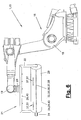
- FIG. 6 illustrates this embodiment in which the robot base body consists of a base and a rocker rotatably mounted thereon, at the upper end of a boom is pivotally mounted, which carries a multi-axis robot hand (19) at the front end and a plurality of engines for the hand axes at the rear end.
- the robot hand (19) has, for example, three rotatory axes. Alternatively, it can also have two hand axes.
- the articulated-arm robot can have one or more additional axles, for example translatory or rotary drive axles.
- the manipulator can have one or more translatory movement axes.
- the manipulators (18) are floor bound. You can alternatively on a frame laterally or over Be hung upside down.
- the working area of the one or more manipulators (18) comprises the end area of the cutting table (5) with the pieces of material (6, 7, 8, 9, 10, 11) provided here and the subsequent storage table (17) and possibly also the laying station (13).
- the manipulators (18) have one or more robot controls (20). In the controls (20) further axes and drives can be connected, which are e.g. in the handling tool (21) or on the delivery table (17) are arranged.
- the position and orientation of the pieces of material (6, 7, 9, 9, 10, 11) in the cross-sectional view and on the cutting table (5) is communicated to the robot controller (20) in a suitable manner, e.g. via an interface of the cutting station (2) and / or via a suitable sensor for detecting the actual position and orientation, e.g. via camera and image analysis.
- a single tray table (17) is provided on which the pieces of material (6, 7, 9, 9, 10, 11) may be juxtaposed one atop the other or, as in the illustrated embodiment, one or more pieces of material stack (42) ,
- the storage table (17) has a flat bearing surface and may comprise guiding or fixing means for the pieces of material (6, 7, 8, 9, 10, 11) or the pieces of material piece (42), for example in the form of a suction device under the supporting surface.
- the storage table (17) can be arranged rigidly. In the illustrated embodiment, it has one or more axes of motion. For example, it can be designed as an xy table and have two horizontal and translatory movement axes in the x and y directions.
- a lifting device may be present in the z-direction.
- only one displacement axis eg in the x or y direction, can be present.
- the axes of motion there is in each case an associated table drive (41), the may be formed in any suitable manner and in particular may be connected to the robot controller (20) and there is controlled as an additional axis together with the robots (18).
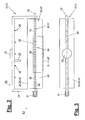
- FIGS. 2 to 5 show a first variant of the handling tool (21) in different views.
- the handling tool (21) in each case has a frame (22) which can be detachably connected to the robot hand (19) via a suitable connection (23).
- a remote controllable or automatic change coupling can be present.
- resource connections such as a power supply and in particular a supply of signal and power currents can be coupled.
- the frame (22) can be moved multiaxially in space by the manipulator (18) and, in particular, can be multi-axially rotated and swiveled by the robot hand (19).
- the frame (22) has a bow-like shape and consists of the cross member with the terminal (23) and two supporting arms projecting therefrom on which at least one material carrier (24) is mounted rigidly or movably.
- the material carrier (24) can be rotatably mounted, driven and controllable.
- the material carrier (24) can in particular have a controllable rotary drive (31) with which the material carrier (24) can be brought into a specific rotational position and positioned relative to a piece of material (6, 7, 8, 10, 10, 11).
- the material carrier (24) is formed like a roller. It may have a solid roll or bar shape, a hollow tube shape, or a cage shape, eg, with multiple parallel bars, and have an arbitrarily shaped, eg, circular, oval, or prismatic cross-section. He takes one or more pieces of material (6, 7, 8, 9, 10, 11) on its circumference or mantle.
- the circumference may be formed as a one-piece or multi-part lateral surface or be formed by an envelope around a rod cage.
- the lateral surface or its surface portions may be flat or curved, wherein the curvature may have one or more axes of curvature and may be uniform or irregular.
- the material carrier (24) may preferably rotate about its possibly central longitudinal axis (30).
- the material carrier (24) can form or have at least one winding carrier (43) with which at least one piece of material (6, 7, 8, 9, 10, 11) is received on the casing by rotation.
- the material carrier (24) can alternatively be configured as a material piece carrier (44) or have at least one material piece carrier (44).
- the piece of material carrier (44) may e.g. consist of a support rod (45) with a prismatic cross-section.
- the winding support (43) may be formed in any suitable manner and serves to form and receive one or more windings (27) each of a piece of material (6,7,8,9,10,11).
- the winding carrier (43) is formed as a substantially cylindrical roller (28) which is rotatably mounted at its two ends in the frame (22) and on the support arms about its longitudinal axis (30).
- the roller shell (29) consists e.g. from a low tack and low friction material, e.g. PTFE.
- the shell texture prevents unwanted adhesion or sticking of parts of the material web (3), in particular of the trimming (12).
- the winding support (43) or the roller (28) is rotatably driven and has for this purpose a controllable rotary drive (31), which is supported on the frame (22).
- the rotary drive (31) can be connected to the robot controller (20) be connected there and is controlled there as an additional axis together with the robots (18).
- One or more pieces of material (6, 7, 8, 9, 10, 11) can be wound on the winding carrier (43) and thereby released from the cutting table (5).
- At least one controllable receiving device (32) for a material piece end (35) is provided for winding on or for the winding formation. It can be brought by the controllable rotary drive (31) in the receiving position to the piece of material (6,7,8,9,10,11).
- the receiving device (32) may have a selection device (33) for adjusting the size of the receiving region (34) and for adapting to the size of the material piece end (35). In this case, it can in particular be adapted to the width of the material piece end (35) in the direction of the roll axis (30) extending width of the receiving area (34).
- the winding carrier (43) can be rotated by the robot hand (19) into the appropriate orientation with the frame (22).
- the selection device (33) it is possible to selectively pick up the desired piece of material (6, 7, 8, 9, 10, 11) and its material piece end (35) from the sectional image on the cutting table (5) and leave the adjacent areas of the web lying , In particular, it can be prevented that the surrounding waste (12) or another piece of unwanted material (6, 7, 8, 9, 10, 11) is picked up and also wound up.
- the receiving device (32) and the selection device (33) can be designed in any suitable manner. In the embodiment shown, they are designed as a controllable suction device (36), which may have a variable suction area size.
- the suction device (36) is arranged on or in the winding support (43) and has one or more in or on the roller shell (29) arranged suction strips (37).
- the suction bars (37) may extend in the straight and along the roller axis (30) as shown. Alternatively, they can be arranged obliquely and arranged, for example, in a partial or circumferential spiral line on the roller shell (29).
- a plurality of identically or differently formed suction strips (37) can be arranged distributed over the circumference or jacket of the material carrier (24) or winding carrier (43). They can be formed by separately controllable vacuum groups (51). FIG. 6 shows an example of such a variant.
- the receiving device (32) can be reversible and facilitate the delivery of the pieces of material (6,7,8,9,10,11).
- the suction device (36) are switched to pressure and blow out air or another fluid.
- the squeegee (37) may be divided into a plurality of switchable suction sections (39).
- the squeegee (37) distributed along the roller axis (30) a plurality of individually or groupwise switchable suction elements (38), for example, have the dot shape shown.
- the suction elements (38) can be connected individually or in groups to at least one vacuum generator.
- the suction elements (38) may consist of simple shell openings with suction lines connected on the back. Alternatively, they may be formed as a suction cup.
- the suction elements (38) individually or in groups may have their own small suction pumps.
- the Suction elements (38) may be designed as small venturable by means of valves and possibly controllable Venturi tubes, which are connected to a compressed air line.
- the suction or pressure lines can be laid individually or designed as a network line.
- any other suitable embodiments of the suction device (36) are possible.
- a squeegee (37) consisting of a row of dots is subdivided into three adjoining suction sections (39), which can be controlled and switched individually.
- the suction device (36) can also be connected to the robot controller (20).
- the winding support (43) is received by the manipulator (18), e.g. positioned opposite the desired piece of material (6, 7, 8, 9, 10, 11) in such a way that the central suction section (39) comes to lie above the piece of material end (35).
- the manipulator (18) e.g. positioned opposite the desired piece of material (6, 7, 8, 9, 10, 11) in such a way that the central suction section (39) comes to lie above the piece of material end (35).
- the manipulator (18) e.g. positioned opposite the desired piece of material (6, 7, 8, 9, 10, 11) in such a way that the central suction section (39) comes to lie above the piece of material end (35).
- the adjacent suction sections (39) are switched off.
- the suction effect only captures the desired material piece end (35) and does not extend to the other material web areas.
- a plurality of suction sections (39) can be connected with negative pressure, wherein the winding carrier (43) is positioned differently. Furthermore, it is possible to simultaneously receive a plurality of adjoining pieces of material (6, 7, 8, 9, 10, 11), for example with the two outer suction portions (39), the middle being switched off, lying around the waste (12) to let.
- the roll (28) can be placed on the desired material piece end (35) with the suction tube (37) turned downwards and positioned in a suitable manner over the rotary drive (31). Subsequently, the negative pressure is switched on and the sucked material piece end (35) with the roller (28) raised by a robot movement a small piece. It is thereby lifted off the cutting table (5) and also lifted out of the surrounding material web area, in particular the adjacent waste (12).
- the winding carrier (43) rotates through the rotary drive (31). This is simultaneously moved with a feed movement of the manipulator (18) transversely or orthogonal to its longitudinal extent.
- the feed rate Vm of the manipulator (18) and the rotational speed Vd of the roller (28) can be matched to each other via the robot controller (20).
- the winding movement can be done without distortion and stress free for the piece of material (6,7,8,9,10,11).
- the winding support (43) can be lowered back onto the piece of material (6, 7, 8, 9, 10, 11) after being wound up and roll on it in the further winding process.
- the formed winding (27) can be multi-layered.
- the direction of rotation and the rotational speed Vd are selected such that the peripheral speed Vu resulting from the roller shell (29) is substantially the same as the feed speed Vm and directed counter to this.
- the tuning of the rotational speed Vd can also depend on the winding thickness, wherein the peripheral speed Vu of the outer winding layer is matched with the feed rate Vm.
- the manipulator (18) transports it to the delivery point, e.g. to the storage table (17), where the piece of material (6,7,8,9,10,11) is unwound and discharged again.
- the tray can be made on the table surface or on the uppermost part of a piece of material stack (42). When dispensing the wound piece of material (6,7,8,9,10,11) may be rotated and stored in a different orientation than it was taken.
- the unwinding can also be done by a superposition of the feed rate Vm and the rotational speed Vd. For this purpose e.g. pull the rear droop piece (35) a distance over the table or stack surface to get the correct alignment. Subsequently, the first slightly raised coil carrier (43) is lowered and the piece of material (6,7,8,9,10,11) unwound. The unwinding can be accelerated by the tray table (17) is moved in the opposite direction to the manipulator feed. The occurring amounts of the feed rates Vm and Vt add up, wherein the rotational speed Vd or the resultant therefrom peripheral speed Vu are increased accordingly and adapted for synchronization. The unwinding can be done faster than the winding process.
- the handling device (15) can have a fluid supply (25) with which an inert fluid can be applied in small quantities to the piece of material (6, 7, 8, 9, 10, 11). Due to its inert nature, the fluid does not react undesirably with the material of the piece of material (6,7,8,9,10,11).
- the fluid can be, for example, water or a liquid resin which, for example, coincides with the impregnating resin of the fiber material or is very similar to it chemically.
- the fluid passes during Unwinding between the substrate and the unwound material piece (6,7,8,9,10,11), wherein it is distributed over the entire surface by the contact pressure to form a very thin adhesive film.
- the adhesive film holds the deposited piece of material (6,7,8,9,10,11) against lateral slipping.
- the fluid supply (25) can be designed and arranged in any suitable manner. You can, for example, the in FIG. 2 have shown training and arranged on the crossbar of the frame (22). It may alternatively be arranged on a support arm and inject the fluid directly when depositing in the gusset between the piece of material (6,7,8,9,10,11) and the substrate. In a further modification, the fluid supply (25) can be arranged elsewhere and be located, for example, on the delivery table (17).
- the handling tool (21) can have one or more measuring devices (26) possibly connected to the control (20).
- This can e.g. one or more distance sensors (40) arranged on the frame (22), e.g. arranged on the upper cross member and directed against the winding (27).
- the distance sensors (40) may e.g. be performed as a laser scanner, which perform a distance measurement by means of transit time measurement of the pulsed laser beam emitted. About the distance measurement of several distributed over the winding width distance sensors (40), the winding formation and the winding shape can be monitored. In addition, the position of the rear material piece end (35) can be detected.
- the measuring device (26) may further include a position measuring device and position encoder for the rotary drive (31), which allow the desired rotational positioning of the winding carrier (43) and the suction strip (37). About the distance sensors (40) and their detection of the squeegee (37) in the upper position of the position sensor can be referenced.
- FIGS. 7 to 11 show different variants of the handling device (15) and in particular of the handling tool (21).
- the handling device (15) can be used in the above-described processing plant (1) with the substantially same function or other equipment and applications.
- the template of the pieces of material (6,7,8,9,10,11) may be different than in the above-described embodiment.
- a single template of the pieces of material (not shown) in any number, arrangement and orientation is possible.
- the handling tool (21) has in each case a plurality of material carriers (24) which are arranged in a suitable manner on the frame (22) rigidly or movably.
- the material carriers (24) are arranged on a revolver (48) which is rotatably mounted on the frame (22) and can be rotated and positioned with a controllable drive (50).
- the revolver (48) has two end faces, e.g. circular support discs (49) with the pivot bearing (not shown). Between the support discs (49) are suitably, e.g. concentric around the central turret axis, several preferably elongate, e.g. roller, rod, tube or cage-shaped material carrier (24) arranged.
- the carrier and turret axes can be parallel.
- the material carriers (24) can in turn be mounted rigidly or movably on the carrier disks (49).
- a rotary bearing is provided, wherein one or more material carriers (24) may also have their own controllable rotary drive (31), which is supported on a support disc (49).
- the material carrier (24) may be formed differently among each other. They can be designed as at least partially hollow body.
- One or more material carriers (24) may e.g. be formed in the manner of the above-described winding carrier (43) and have rollers or tubes with a circular or oval cross-section. The winding process can take place in the manner described above, wherein the winding carrier (43) rotates in the revolver (48) and receives the winding ((27) or subsequently gives off.
- One or more other material carriers (24) are configured as material piece carriers (44), each consisting of a carrier bar (45) with a prismatic cross section. Due to the prismatic shape, a plurality of support surfaces (46, 47) are formed on the outer circumference or jacket of the carrier rod (45), which can have a substantially planar or single or multi-axial arched shape.
- the curvature of the curvature may be weak and adapted to the elasticity of the piece of material.
- the edges at the surface transitions may be rounded.
- the material carriers (24) in the revolver (48) are individually controllable in their positioning and in their recording and dispensing function.
- the material piece carriers (44) with the carrier surfaces (46) are designed in particular for receiving pieces of material with a corresponding shape and can retain them.
- a winding process does not have to take place. On the other hand, however, this is also not excluded, with rounded edges at the transitions of the carrier surfaces (47) and a slightly curved carrier surface form being favorable for a winding function.
- a winding can be formed on at least one rotating material carrier (24). Alternatively, a winding is formed on the turret (48) by its rotation possible.
- the pieces of material can, as in the first embodiment, be mat-like and flexible or otherwise, in particular largely inflexible.
- the support surfaces (46) have a flat or slightly curved shape, they can be placed substantially flat on the provided on a template pieces of material and record them in a suitable manner, for example by the aforementioned suction function, by needles, grippers or other suitable recording tools , Also with the variants of FIGS. 7 to 11 There may be one or more receiving devices (32) and one or more selection devices (33) of the type described above with corresponding constructive and functional adaptation. The pieces of material can also be dispensed again in the manner described above.
- the revolver (48) can form an intermediate storage for the said pieces of material by means of the multiple material carriers (24) and the possibility given thereby for receiving a plurality of pieces of material (6, 7, 8, 9, 10, 11) and that in the first embodiment Replace the storage table (17) described above. It also forms a magazine for different material carriers (24).
- the turret (48) offers with its memory function, the ability to select the picking and dispensing order of the pieces of material (6,7,8,9,10,11) and the receiving and dispensing locations arbitrarily and also to change.
- the pieces of material (6, 7, 8, 9, 10, 11) can in particular be picked up in an order and delivered or stored in a different order.
- the recording and dispensing sequences can thereby be adapted to the respective and possibly different requirements by, for example, pieces of material (6, 7, 9, 9, 10, 11) of a plurality of originals are picked up one after the other and sorted then released in a mix of varieties and possibly also placed on top of each other.
- the pieces of material (6,7,8,9,10,11) can be picked up individually and independently and held on the turret (48). Due to the single access, they can also be dispensed independently.
- the plurality of material carriers (24) can each be provided with their own suction device (36) or connected to a common suction device (36). They have on the circumference of a plurality of suction elements (38), which can be grouped as in the aforementioned embodiment to Saugleisten (37) or other, in particular planar forms of Sauger phenomenon (51).
- the support rods (45) can have different types of suction groups (51) on their different support surfaces (46, 47). Within groups, the individual suction elements (38) are arranged differently, resulting in different suction pattern (52), as they are eg in FIG. 7 are shown.
- the support surfaces (46, 47) and their suction groups (51) can thereby be adapted to different types of material pieces (6, 7, 8, 9, 10, 11), which differ, for example, in terms of their shape and size. Due to the variety of variants of the suction pattern (52), the handling device (21) is highly flexible and can be used for a wide variety of applications.
- One or more additional tools (53) can be arranged on the revolver (48) or also on one or more individual material carriers (24). You can act process-supporting in the recording and / or delivery of the pieces of material or have other auxiliary and support functions.
- One or more such additional tools (53) can also in the above-described embodiment of Figure 1 to 6 be present with a single winding support (43).
- an additional tool (53) is shown, which is designed as a pivotable bracket (54) which moves by means of an adjusting device (55) to a material carrier (24) out and can be removed.
- the bracket (54) can for example act as a holder with which a recorded piece of material on the material carrier (24) can be held.
- a winding carrier (43) for example, when winding on, the front material piece end (35) can be held in place additionally and temporarily.
- the rear free material end can be pressed against the roll and held fast.
- the bracket (54) is eg in the in FIG. 11 manner shown by means of a bearing (56) pivotally mounted on a support disc (49) and has an angled shape.
- the controllable adjusting device (55) has an actuating drive (57) acting on the bow arm, which can be formed, for example, by a pneumatic cylinder.
- accessory tools (53) may be knives, punches, coating devices, means for printing or labeling or embossing one or more pieces of material.
- brushes or other cleaning tools may be present and arranged, for example, on a carrier surface (46, 47).
- Said additional tools (53) can be arranged rigidly or movably on the handling tool (21). Movable or swiveling knives can, for example, cut off pieces of material.
- FIG. 9 illustrates a further variant in which an additional tool (53) instead of a material carrier (24) on the turret (48) is arranged.
- the additional tool (53) may be, for example, a rigid or movable brush (58), in particular a rotatable brush roller.
- the brush (58) for example, the cutting table (5) or the storage table (17) can be cleaned.
- the waste (12) with the brush (58) can be turned away into a waste receptacle.
- the brush (58) or another cleaning tool and the pieces of material (6,7,8,9,10,11) can be edited and in particular cleaned.
- Such an additional tool (53) can, for example, also assist the dispensing of the material pieces (6, 7, 6, 9, 9, 10, 11) and enable their subsequent treatment or reworking.
- the additional tool (53) may be formed as a pressure roller, ironing roller or the like.
- an additional tool (53) for cleaning or otherwise treating the material carrier (24) may be provided. This can e.g. be a scraper, which possibly material residues from the roller shell (29) or the support surfaces (46,47) and possibly also cleans the suction elements (38).
- the material carrier (24) can exercise one or more additional functions in addition to the reception and delivery of pieces of material (6,7,8,9,10,11). For example, adhesive strips or the like can be removed from a dispenser (not shown) with a material carrier (24) and placed on a delivery table (17) or another base on which a piece of material (6, 7, 8, 9, 10, 11) should be launched.
- a dispenser not shown
- the multiple arrangement of material carriers (24) and in particular the revolver (48) is particularly favorable.
- the material carrier (24) have in the illustrated embodiments, a substantially mittensymmetrische shape and are also mounted substantially centrally symmetrical rotation. Alternatively, an asymmetrical cross-sectional shape and / or an off-center bearing may be present.
- the carrier cross section may e.g. have the outline of a flattened on one or more side oval or circle.
- one or more material carriers (24) can be attached to the frame (22) with one or more additional axes, e.g. be additionally movably mounted by means of a link assembly or the like. Such an arrangement is also possible in connection with a revolver (48). Corresponding additional axes are also possible for one or more additional tools (53).
- a plurality of material carriers (24) can thereby simultaneously come into operation, whereby e.g. several pieces of material are stacked on top of each other or simultaneously deposited and post-treated, e.g. Pressed, cleaned or the like. Become.
- the handling tool (21) can be exchangeable.
- a removable coupling between the robot hand (19) and the frame (22) may be arranged.
- the processing system (1) may have a magazine for a plurality of handling tools (21), which can be replaced if necessary.
- a handling device 21
- eg a revolver 48
- the replacement can also be done automatically or by hand in the cases mentioned.
- the handling tool (21) can have a plurality of material carriers (24) mounted relatively stationarily on the frame (22).
- the handling tool (21) can also have a different exchange device for receiving a plurality of material carriers (24) and for positioning the respectively desired material carrier (24) at the required functional point.
- the described embodiments for the function and operation of a revolver (48) can be adapted accordingly to these modifications of the handling tool (21).
- rollers or wraps otherwise prepared e.g. Roof cardboard rolls, picked up and stored and delivered in the desired manner.
- e.g. roofing board on a roof can be automatically and automatically rolled out and stored.
- the manipulator (18) can be designed for this purpose in a suitable manner and, for example. be arranged as articulated arm robot on a truck movable. The robot arms have a correspondingly large length and allow folding in for transport.
- the receiving device (32) can be equipped with mechanical gripping elements, eg with needles, hooks or the like, with which mechanically insensitive or deformation-tolerant material pieces (6, 7, 8, 9, 10, 11) can be gripped.
- the winding can also be done by a multiple arrangement of rollers or rollers with clamping of the material piece end (35).
- two or more manipulators (18) may be arranged to work in concert.
Landscapes
- Engineering & Computer Science (AREA)
- Mechanical Engineering (AREA)
- Robotics (AREA)
- Chemical & Material Sciences (AREA)
- Composite Materials (AREA)
- Treatment Of Fiber Materials (AREA)
- Sheets, Magazines, And Separation Thereof (AREA)
- Feeding Of Articles By Means Other Than Belts Or Rollers (AREA)
Applications Claiming Priority (1)
| Application Number | Priority Date | Filing Date | Title |
|---|---|---|---|
| DE202007006528U DE202007006528U1 (de) | 2007-05-04 | 2007-05-04 | Einrichtung zum Handhaben von Materialstücken |
Publications (3)
| Publication Number | Publication Date |
|---|---|
| EP1992456A2 true EP1992456A2 (fr) | 2008-11-19 |
| EP1992456A3 EP1992456A3 (fr) | 2009-01-21 |
| EP1992456B1 EP1992456B1 (fr) | 2011-06-15 |
Family
ID=39689451
Family Applications (1)
| Application Number | Title | Priority Date | Filing Date |
|---|---|---|---|
| EP08008410A Ceased EP1992456B1 (fr) | 2007-05-04 | 2008-05-05 | Procédé et dispositif de manipulation d'objets flexibles en forme de tapis |
Country Status (2)
| Country | Link |
|---|---|
| EP (1) | EP1992456B1 (fr) |
| DE (1) | DE202007006528U1 (fr) |
Cited By (11)
| Publication number | Priority date | Publication date | Assignee | Title |
|---|---|---|---|---|
| DE102008052359A1 (de) * | 2008-10-20 | 2010-04-22 | Koch Industrieanlagen Gmbh | Greifer |
| ITBO20100514A1 (it) * | 2010-08-06 | 2012-02-07 | Giuseppe Gallucci | Dispositivo per lo scarico, da un piano di lavoro, di articoli piani nei quali sono ricavate, mediante taglio e/o incisione, porzioni su cui sono riprodotti disegni e/o scritte |
| EP2505706A1 (fr) * | 2011-03-02 | 2012-10-03 | Premium AEROTEC GmbH | Dispositif de drapage |
| JP2014522747A (ja) * | 2011-06-22 | 2014-09-08 | ザ・ボーイング・カンパニー | プライ自動積層システム及び積層方法 |
| WO2018153829A1 (fr) * | 2017-02-27 | 2018-08-30 | Kuka Deutschland Gmbh | Pince de robot destinée à manipuler des découpes de bande de matériau planes et souples |
| GB2566589A (en) * | 2017-08-03 | 2019-03-20 | Gen Electric | Multi-faced apparatus and system for automated handling of components |
| CN112339276A (zh) * | 2019-08-06 | 2021-02-09 | 中国科学院宁波材料技术与工程研究所 | 一种纤维增强热塑性预浸片材叠层成型生产线装置及工艺 |
| CN114232315A (zh) * | 2021-12-14 | 2022-03-25 | 江苏坤泰机械有限公司 | 一种移动式裁断机的自动收料装置 |
| CN116605686A (zh) * | 2023-06-30 | 2023-08-18 | 长治学院 | 用于布料加工的布料原料抓取设备 |
| CN116867612A (zh) * | 2020-12-09 | 2023-10-10 | 赫法控股有限责任公司 | 用于自动移除柔性材料部件的移除设备、用于移除柔性材料的方法以及包含输送设备和移除设备的生产设施 |
| CN116945132A (zh) * | 2017-08-02 | 2023-10-27 | 伯克希尔格雷营业股份有限公司 | 用于获取和移动具有复杂的外表面的物体的系统和方法 |
Families Citing this family (16)
| Publication number | Priority date | Publication date | Assignee | Title |
|---|---|---|---|---|
| DE102010011888B4 (de) * | 2010-03-18 | 2017-06-29 | Lsi Ludwig Schleicher Ingenium Gmbh & Co. Kg | Vorrichtung zum Manipulieren von Kohlenstoff-Faser-Flächenelementen |
| CH704406A1 (de) * | 2011-01-31 | 2012-07-31 | Kringlan Composites Ag | Verfahren zur Herstellung von Vorformen. |
| DE202012008988U1 (de) | 2012-09-19 | 2012-10-25 | Alpha-Tec Krimpmann Gmbh | Handhabungseinrichtung mit einem Manipulator für Materialstücke |
| DE102012018438B4 (de) | 2012-09-19 | 2018-12-13 | Eisenmann Alpha-Tec Gmbh | Handhabungseinrichtung mit einem Manipulator für Materialstücke |
| DE102013207723B4 (de) * | 2013-04-26 | 2020-06-18 | Innfa Gmbh | Verfahren und Vorrichtung zur Herstellung von Faserverbund-Teilen |
| DE102013104609B4 (de) * | 2013-05-06 | 2016-10-20 | Deutsches Zentrum für Luft- und Raumfahrt e.V. | Nestingablage |
| DE102014205479B4 (de) * | 2014-03-25 | 2025-03-27 | Bayerische Motoren Werke Aktiengesellschaft | Verfahren zur Herstellung eines Faservorformlings für ein Faserverbundbauteil |
| DE102014213475A1 (de) * | 2014-07-10 | 2016-01-14 | Bayerische Motoren Werke Aktiengesellschaft | Verfahren zum Zusammenfügen von zwei oder mehr Einzellagen aus Faserstrukturen zu einem Stapel |
| DE102014218978A1 (de) * | 2014-09-22 | 2016-03-24 | Bayerische Motoren Werke Aktiengesellschaft | Vorrichtung und Verfahren zum Platzieren von Fasermaterial |
| DE102015201551A1 (de) * | 2015-01-29 | 2016-08-04 | Bayerische Motoren Werke Aktiengesellschaft | Erkennungsvorrichtung für die Erkennung einer Ausrichtung von Halbzeugzuschnitten |
| DE102016003816B4 (de) * | 2016-03-26 | 2019-05-29 | Audi Ag | Industrieroboter mit einem am Manipulator mitgeführten Überwachungsraum |
| US10710262B2 (en) * | 2016-12-06 | 2020-07-14 | Arm Automation, Inc. | Tool and method for separating and picking cut pieces of flexible materials |
| CN108221353B (zh) * | 2016-12-09 | 2020-11-10 | 宁波市东盛纺织有限公司 | 一种全自动布料裁剪方法 |
| EP4324603A3 (fr) | 2018-08-13 | 2024-06-05 | Boston Dynamics, Inc. | Manipulation de boîtes à l'aide d'un dispositif de préhension à zones |
| AT523962B1 (de) | 2020-07-08 | 2023-05-15 | Gfm Gmbh | Verfahren zum Bereitstellen von Zuschnitten aus einer Faserbahn |
| AT523964B1 (de) | 2020-07-08 | 2023-05-15 | Gfm Gmbh | Verfahren zum Bereitstellen von Zuschnitten aus einer Faserbahn |
Citations (3)
| Publication number | Priority date | Publication date | Assignee | Title |
|---|---|---|---|---|
| US4677778A (en) | 1983-01-07 | 1987-07-07 | Canon Kabushiki Kaisha | Sheet manipulating apparatus |
| JPH0769470A (ja) | 1993-06-30 | 1995-03-14 | Morihiko Mizumura | シート部材の取上げ装置 |
| US20040089516A1 (en) | 2001-06-29 | 2004-05-13 | The Procter & Gamble Company | Method and apparatus utilizing servo motors for placing parts onto a moving web |
Family Cites Families (17)
| Publication number | Priority date | Publication date | Assignee | Title |
|---|---|---|---|---|
| US3127167A (en) * | 1964-03-31 | Sheet stacker or feeder | ||
| DE2111637A1 (de) * | 1970-03-17 | 1971-10-07 | Ct D Etudes Tech Des Ind De L | Vorrichtung zum Erfassen von Materialien durch Ansaugen |
| US4317694A (en) | 1980-08-27 | 1982-03-02 | Evana Tool & Engineering Company | Laminate applying machine and method |
| CA1226593A (fr) * | 1983-09-07 | 1987-09-08 | Dunlop Olympic Limited | Appareil et methode suivant a separer et a transporter des morceaux de tissu |
| FR2555558B1 (fr) * | 1983-11-29 | 1986-10-24 | Redoute Catalogue | Dispositif de prehension unitaire d'articles disposes en vrac |
| US4954033A (en) * | 1984-06-11 | 1990-09-04 | Unico, Inc. | Transfer mechanism for conveyor |
| FR2664883B1 (fr) * | 1990-07-20 | 1993-03-19 | Esatec | Margeur rotatif pour le placement precis d'elements en feuille sur des supports plats. |
| DE4026969C2 (de) | 1990-08-25 | 1994-03-24 | Deutsche Aerospace Airbus | Zuschneidevorrichtung für vorimprägniertes Fasermaterial |
| DE59503157D1 (de) * | 1995-01-13 | 1998-09-17 | Ferag Ag | Vorrichtung zum Öffnen von Druckereiprodukten und Einrichtung zum Verarbeiten von Druckereiprodukten |
| US5779830A (en) | 1995-10-24 | 1998-07-14 | Truseal Technologies, Inc. | Flexible tape applicator and method of operation |
| JP3859862B2 (ja) | 1998-04-20 | 2006-12-20 | セントラル硝子株式会社 | 粘着テープの貼付方法および装置 |
| US6213286B1 (en) * | 1998-10-20 | 2001-04-10 | The Mead Corporation | Adjustable carton feeder |
| EP1181118B1 (fr) | 1999-04-07 | 2004-12-08 | Amada Company, Limited | Systeme de cintrage automatique |
| US6139004A (en) * | 1999-07-01 | 2000-10-31 | Kimberly-Clark Worldwide, Inc. | Assembly and method for rotating and placing strip of material on a substrate |
| US20040042789A1 (en) * | 2002-08-30 | 2004-03-04 | Celanese Ventures Gmbh | Method and apparatus for transferring thin films from a source position to a target position |
| US7601237B2 (en) * | 2006-02-01 | 2009-10-13 | The Boeing Company | Fabric handling apparatus and method for composite manufacture |
| PL2041010T3 (pl) * | 2006-07-17 | 2012-03-30 | Celli Nonwovens Spa | Zautomatyzowany układ do wytwarzania i obsługiwania rolek materiału zwojowego oraz robot przeznaczony szczególnie do wymienionego układu |
-
2007
- 2007-05-04 DE DE202007006528U patent/DE202007006528U1/de not_active Expired - Lifetime
-
2008
- 2008-05-05 EP EP08008410A patent/EP1992456B1/fr not_active Ceased
Patent Citations (3)
| Publication number | Priority date | Publication date | Assignee | Title |
|---|---|---|---|---|
| US4677778A (en) | 1983-01-07 | 1987-07-07 | Canon Kabushiki Kaisha | Sheet manipulating apparatus |
| JPH0769470A (ja) | 1993-06-30 | 1995-03-14 | Morihiko Mizumura | シート部材の取上げ装置 |
| US20040089516A1 (en) | 2001-06-29 | 2004-05-13 | The Procter & Gamble Company | Method and apparatus utilizing servo motors for placing parts onto a moving web |
Cited By (23)
| Publication number | Priority date | Publication date | Assignee | Title |
|---|---|---|---|---|
| DE102008052359B4 (de) * | 2008-10-20 | 2012-04-19 | Koch Industrieanlagen Gmbh | Greifer |
| DE102008052359A1 (de) * | 2008-10-20 | 2010-04-22 | Koch Industrieanlagen Gmbh | Greifer |
| US8915171B2 (en) | 2010-08-06 | 2014-12-23 | Giuseppe Gallucci | Device for unloading flat articles from a work plane, flat articles including portions on which designs and/or writing is reproduced by cutting and/or incision |
| ITBO20100514A1 (it) * | 2010-08-06 | 2012-02-07 | Giuseppe Gallucci | Dispositivo per lo scarico, da un piano di lavoro, di articoli piani nei quali sono ricavate, mediante taglio e/o incisione, porzioni su cui sono riprodotti disegni e/o scritte |
| WO2012017336A1 (fr) * | 2010-08-06 | 2012-02-09 | Giuseppe Gallucci | Dispositif de déchargement d'articles plats à partir d'un plan de travail, les articles plats comprenant des parties sur lesquelles sont reproduits des motifs et/ou un texte par découpage et/ou par incision |
| EP2505706A1 (fr) * | 2011-03-02 | 2012-10-03 | Premium AEROTEC GmbH | Dispositif de drapage |
| US8668796B2 (en) | 2011-03-02 | 2014-03-11 | Premium Aerotec Gmbh | Draping device for textile semi-finished products |
| JP2014522747A (ja) * | 2011-06-22 | 2014-09-08 | ザ・ボーイング・カンパニー | プライ自動積層システム及び積層方法 |
| US9969131B2 (en) | 2011-06-22 | 2018-05-15 | The Boeing Company | Automated ply layup system |
| WO2018153829A1 (fr) * | 2017-02-27 | 2018-08-30 | Kuka Deutschland Gmbh | Pince de robot destinée à manipuler des découpes de bande de matériau planes et souples |
| CN116945132A (zh) * | 2017-08-02 | 2023-10-27 | 伯克希尔格雷营业股份有限公司 | 用于获取和移动具有复杂的外表面的物体的系统和方法 |
| US12544915B2 (en) | 2017-08-02 | 2026-02-10 | Berkshire Grey Operating Company, Inc. | Systems and methods for acquiring and moving objects having complex outer surfaces |
| EP4299260A3 (fr) * | 2017-08-02 | 2024-04-10 | Berkshire Grey Operating Company, Inc. | Systèmes et procédés d'acquisition et de déplacement d'objets présentant des surfaces extérieures complexes |
| GB2566589A (en) * | 2017-08-03 | 2019-03-20 | Gen Electric | Multi-faced apparatus and system for automated handling of components |
| GB2566589B (en) * | 2017-08-03 | 2020-03-25 | Gen Electric | Multi-faced apparatus and system for automated handling of components |
| CN112339276B (zh) * | 2019-08-06 | 2022-11-15 | 中国科学院宁波材料技术与工程研究所 | 一种纤维增强热塑性预浸片材叠层成型生产线装置及工艺 |
| CN112339276A (zh) * | 2019-08-06 | 2021-02-09 | 中国科学院宁波材料技术与工程研究所 | 一种纤维增强热塑性预浸片材叠层成型生产线装置及工艺 |
| CN116867612A (zh) * | 2020-12-09 | 2023-10-10 | 赫法控股有限责任公司 | 用于自动移除柔性材料部件的移除设备、用于移除柔性材料的方法以及包含输送设备和移除设备的生产设施 |
| JP2023552603A (ja) * | 2020-12-09 | 2023-12-18 | ヘーファ ホールディングス ゲーエムベーハー | 可撓性材料部品を自動で取り外すための取外し装置、可撓性材料部品を取り外すための方法、並びに搬送装置及び取外し装置を備える生産設備 |
| US12552620B2 (en) | 2020-12-09 | 2026-02-17 | Hefa Holding Gmbh | Removal device for automatically removing flexible material parts, method for removing flexible material parts, and production system comprising a conveyor device and a removal device |
| CN114232315A (zh) * | 2021-12-14 | 2022-03-25 | 江苏坤泰机械有限公司 | 一种移动式裁断机的自动收料装置 |
| CN116605686A (zh) * | 2023-06-30 | 2023-08-18 | 长治学院 | 用于布料加工的布料原料抓取设备 |
| CN116605686B (zh) * | 2023-06-30 | 2023-09-15 | 长治学院 | 用于布料加工的布料原料抓取设备 |
Also Published As
| Publication number | Publication date |
|---|---|
| DE202007006528U1 (de) | 2008-09-18 |
| EP1992456A3 (fr) | 2009-01-21 |
| EP1992456B1 (fr) | 2011-06-15 |
Similar Documents
| Publication | Publication Date | Title |
|---|---|---|
| EP1992456B1 (fr) | Procédé et dispositif de manipulation d'objets flexibles en forme de tapis | |
| EP3736235B1 (fr) | Dispositif de manipulation de pile de produits pliés, plieuse correspondante, et procédé de transfert de piles de produits | |
| DE4130269C2 (de) | Verfahren und Vorrichtung zum Herstellen laminierter Prepreg-Teile | |
| EP1436140B1 (fr) | Procede et dispositif pour manipuler de facon automatisee des mats impregnes de resine lors de la production de pieces en smc | |
| DE10035237C1 (de) | Verfahren und Produktionsanlage zum Herstellen von schalenförmigen, fasermatten-verstärkten Kunststoffteilen | |
| DE102010002002B4 (de) | Verfahren und Vorrichtung zum Unwuchtausgleich an einem Fahrzeugrad | |
| DE69208722T2 (de) | Integriertes automatisiertes Herstellungssystem und Verfahren zur Herstellung von Verbundwerkstoff | |
| DE19642831C2 (de) | Verfahren und Vorrichtung zum Applizieren von selbsthaftender Schutzfolie auf Karosserien | |
| DE202007000899U1 (de) | Einrichtung zum Handhaben von flexiblen mattenartigen Materialstücken | |
| EP2144830A2 (fr) | Procédé et dispositif pour emballer des grands emballages pour bouteilles | |
| DE102015002777A1 (de) | Faserlegemaschine | |
| EP1519829A1 (fr) | Procede et dispositif destines a l'application automatique d'un film de peinture sur les pieces de carrosserie et composite film de peinture compatible avec l'automatisation | |
| DE102015002775A1 (de) | System zur Fertigung von Faser-Verbundbauteilen | |
| DE69505334T2 (de) | Produktionsmaschine mit Bahnrollenzufuhr und Abfuhr leerer Kernhülsen | |
| EP4259386B1 (fr) | Dispositif de retrait pour le retrait automatique de pièces de matériau souples, procédé pour retirer des pièces de matériau souples, et installation de production comprenant un dispositif de transport et un dispositif de retrait | |
| WO2018153829A1 (fr) | Pince de robot destinée à manipuler des découpes de bande de matériau planes et souples | |
| EP1603734B1 (fr) | Procede et dispositif d'application automatique de film de laque sur des pieces de carrosserie, et utilisation a cet effet d'une bande auto-adhesive tendue | |
| DE69907789T2 (de) | Verfahren und Vorrichtung zum Zuführen von Rollen | |
| WO2019057241A1 (fr) | Procédé et dispositif de manipulation et de dépôt continus de textiles techniques, notamment sous la forme d'un paquet de couches textiles dans un outil de formage | |
| EP1564168A1 (fr) | Mandrin avec des aiguilles de recuperation | |
| EP2234794B1 (fr) | Procédé et dispositif pour déposer une matière enroulée | |
| DE10118386B4 (de) | Ladevorrichtung mit gezielter Sauggreifersteuerung | |
| EP4392215A1 (fr) | Porte-outil destiné à un outil de perforation, système qui possède une machine de traitement, un porte-outil, et un moyen de levage, et procédé de changement d'un outil de perforation | |
| EP0159520A1 (fr) | Dispositif pour amener et évacuer l'ouvrage sur machine à coudre | |
| DE102022101574A1 (de) | Hebezeug zur Handhabung von mindestens einem Stanzwerkzeug, System aufweisend eine Bearbeitungsmaschine und mindestens ein Hebezeug und Verfahren zum Wechseln mindestens eines Stanzwerkzeugs |
Legal Events
| Date | Code | Title | Description |
|---|---|---|---|
| PUAI | Public reference made under article 153(3) epc to a published international application that has entered the european phase |
Free format text: ORIGINAL CODE: 0009012 |
|
| AK | Designated contracting states |
Kind code of ref document: A2 Designated state(s): AT BE BG CH CY CZ DE DK EE ES FI FR GB GR HR HU IE IS IT LI LT LU LV MC MT NL NO PL PT RO SE SI SK TR |
|
| AX | Request for extension of the european patent |
Extension state: AL BA MK RS |
|
| PUAL | Search report despatched |
Free format text: ORIGINAL CODE: 0009013 |
|
| AK | Designated contracting states |
Kind code of ref document: A3 Designated state(s): AT BE BG CH CY CZ DE DK EE ES FI FR GB GR HR HU IE IS IT LI LT LU LV MC MT NL NO PL PT RO SE SI SK TR |
|
| AX | Request for extension of the european patent |
Extension state: AL BA MK RS |
|
| RIC1 | Information provided on ipc code assigned before grant |
Ipc: B25J 15/00 20060101AFI20080922BHEP Ipc: D06H 7/24 20060101ALI20081215BHEP Ipc: B25J 15/06 20060101ALI20081215BHEP Ipc: B65H 29/00 20060101ALI20081215BHEP Ipc: B65G 17/32 20060101ALI20081215BHEP |
|
| 17P | Request for examination filed |
Effective date: 20090708 |
|
| 17Q | First examination report despatched |
Effective date: 20090807 |
|
| AKX | Designation fees paid |
Designated state(s): DE GB |
|
| GRAP | Despatch of communication of intention to grant a patent |
Free format text: ORIGINAL CODE: EPIDOSNIGR1 |
|
| GRAS | Grant fee paid |
Free format text: ORIGINAL CODE: EPIDOSNIGR3 |
|
| GRAA | (expected) grant |
Free format text: ORIGINAL CODE: 0009210 |
|
| AK | Designated contracting states |
Kind code of ref document: B1 Designated state(s): DE GB |
|
| REG | Reference to a national code |
Ref country code: GB Ref legal event code: FG4D Free format text: NOT ENGLISH |
|
| REG | Reference to a national code |
Ref country code: DE Ref legal event code: R096 Ref document number: 502008003831 Country of ref document: DE Effective date: 20110728 |
|
| PLBE | No opposition filed within time limit |
Free format text: ORIGINAL CODE: 0009261 |
|
| STAA | Information on the status of an ep patent application or granted ep patent |
Free format text: STATUS: NO OPPOSITION FILED WITHIN TIME LIMIT |
|
| 26N | No opposition filed |
Effective date: 20120316 |
|
| REG | Reference to a national code |
Ref country code: DE Ref legal event code: R097 Ref document number: 502008003831 Country of ref document: DE Effective date: 20120316 |
|
| PGFP | Annual fee paid to national office [announced via postgrant information from national office to epo] |
Ref country code: DE Payment date: 20190423 Year of fee payment: 12 |
|
| PGFP | Annual fee paid to national office [announced via postgrant information from national office to epo] |
Ref country code: GB Payment date: 20190501 Year of fee payment: 12 |
|
| REG | Reference to a national code |
Ref country code: DE Ref legal event code: R119 Ref document number: 502008003831 Country of ref document: DE |
|
| GBPC | Gb: european patent ceased through non-payment of renewal fee |
Effective date: 20200505 |
|
| PG25 | Lapsed in a contracting state [announced via postgrant information from national office to epo] |
Ref country code: GB Free format text: LAPSE BECAUSE OF NON-PAYMENT OF DUE FEES Effective date: 20200505 |
|
| PG25 | Lapsed in a contracting state [announced via postgrant information from national office to epo] |
Ref country code: DE Free format text: LAPSE BECAUSE OF NON-PAYMENT OF DUE FEES Effective date: 20201201 |