EP1992500A1 - Radblende für ein Kraftfahrzeug - Google Patents
Radblende für ein Kraftfahrzeug Download PDFInfo
- Publication number
- EP1992500A1 EP1992500A1 EP07425278A EP07425278A EP1992500A1 EP 1992500 A1 EP1992500 A1 EP 1992500A1 EP 07425278 A EP07425278 A EP 07425278A EP 07425278 A EP07425278 A EP 07425278A EP 1992500 A1 EP1992500 A1 EP 1992500A1
- Authority
- EP
- European Patent Office
- Prior art keywords
- hub
- hub cap
- base
- teeth
- cap according
- Prior art date
- Legal status (The legal status is an assumption and is not a legal conclusion. Google has not performed a legal analysis and makes no representation as to the accuracy of the status listed.)
- Withdrawn
Links
- 230000008878 coupling Effects 0.000 claims abstract description 26
- 238000010168 coupling process Methods 0.000 claims abstract description 26
- 238000005859 coupling reaction Methods 0.000 claims abstract description 26
- 230000003014 reinforcing effect Effects 0.000 claims description 6
- 239000000463 material Substances 0.000 claims description 4
- 230000000737 periodic effect Effects 0.000 claims 1
- 238000000605 extraction Methods 0.000 description 2
- 239000007769 metal material Substances 0.000 description 2
- 239000000853 adhesive Substances 0.000 description 1
- 238000004026 adhesive bonding Methods 0.000 description 1
- 230000001070 adhesive effect Effects 0.000 description 1
- 230000001419 dependent effect Effects 0.000 description 1
- ZZUFCTLCJUWOSV-UHFFFAOYSA-N furosemide Chemical compound C1=C(Cl)C(S(=O)(=O)N)=CC(C(O)=O)=C1NCC1=CC=CO1 ZZUFCTLCJUWOSV-UHFFFAOYSA-N 0.000 description 1
- 230000002452 interceptive effect Effects 0.000 description 1
- 238000000465 moulding Methods 0.000 description 1
- 230000002093 peripheral effect Effects 0.000 description 1
- 230000003252 repetitive effect Effects 0.000 description 1
Images

Classifications
-
- B—PERFORMING OPERATIONS; TRANSPORTING
- B60—VEHICLES IN GENERAL
- B60B—VEHICLE WHEELS; CASTORS; AXLES FOR WHEELS OR CASTORS; INCREASING WHEEL ADHESION
- B60B7/00—Wheel cover discs, rings, or the like, for ornamenting, protecting, venting, or obscuring, wholly or in part, the wheel body, rim, hub, or tyre sidewall, e.g. wheel cover discs, wheel cover discs with cooling fins
- B60B7/0013—Hub caps
-
- B—PERFORMING OPERATIONS; TRANSPORTING
- B60—VEHICLES IN GENERAL
- B60B—VEHICLE WHEELS; CASTORS; AXLES FOR WHEELS OR CASTORS; INCREASING WHEEL ADHESION
- B60B7/00—Wheel cover discs, rings, or the like, for ornamenting, protecting, venting, or obscuring, wholly or in part, the wheel body, rim, hub, or tyre sidewall, e.g. wheel cover discs, wheel cover discs with cooling fins
- B60B7/06—Fastening arrangements therefor
- B60B7/08—Fastening arrangements therefor having gripping elements consisting of formations integral with the cover
Definitions
- the object of the present invention is a hub cap for a vehicle wheel.
- hub caps are widely used, especially in the field of motor vehicles, for aesthetic purposes, that is, for covering the central opening of the rim and often, they serve as a support for the manufacturer's brand.
- the hub cap exhibits the tendency to vibrate, even noisily, negatively affecting the vehicle comfort.
- the object of the present invention is to provide a hub cap for vehicle wheels provided with a coupling system to the hub which should be easy to mount, easy to remove and which should prevent or strongly limit the onset of vibrations at the same time.
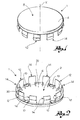
- FIG. 1 shows a perspective front view of the hub cap according to an embodiment variation of the present invention
- figure 2 shows a perspective back view of the hub cap of figure 1 ;
- FIG. 3 shows a cross section view of a portion of the hub cap engaged with a portion of the hub
- FIG. 4 shows a cross section view of a further portion of the hub cap engaged with a further portion of the hub.
- reference numeral 1 globally indicates a hub cap, according to an embodiment variation of the present invention, suitable for being removably associated to a hub H of a wheel, centrally provided with an opening O.
- the hub cap 1 comprises a base 2, generally with a discoid shape, having a main axis X, provided with an outer surface 4, intended for facing outwards of the vehicle with hub cap mounted on the wheel, and an inner surface 6, opposite the outer surface.
- Base 2 is sized for covering, at least partly, opening O of hub H.
- hub cap 1 further comprises a covering 8, suitable for covering at least partly the outer surface 4 of base 2.
- covering 8 has a brand.
- covering 8 extends so as to cover also the edge of base 2, folding along the thickness thereof.
- hub cap 1 comprises retaining means suitable for making covering 8 integral with base 2.
- the retaining means comprise at least one folding tab 10, protruding from the covering, for example peripherally thereof.
- a plurality tabs 10 are provided, circumferentially spaced, for example at constant regular intervals.
- Tabs 10 folded on the inner surface 6 of base 4, retain covering 8 to base 2.
- the folding of the tabs is carried out by caulking.
- the retaining means comprise ad adhesive material, placed on the outer surface 4 of base 2, for gluing covering 8 to base 2.
- the outer surface 4 of bottom base 2 is decorated and the hub cap is free from a covering thereof.
- the covering is made in a single piece, of a metal material.
- the main axis X of base 2 is central and perpendicular to the outer surface 4 thereof, so as to define also the mounting direction, according to which the hub cap is pushed in opening O of hub H for being mounted.
- hub cap 1 comprises engagement means suitable for engaging the hub cap with opening O of hub H.
- the engagement means comprise a plurality of teeth protruding peripherally from base 2, along the direction of the main axis X, circumferentially spaced.
- the teeth exhibit different structural features, so that they can be distinguished into at least two groups: a first group of coupling teeth 12 and a second group of abutment teeth 14.
- the coupling teeth 12 are shaped for obtaining a snap-wise coupling with the wall that delimits opening O of hub H.
- the coupling tooth 12 comprises a tooth wall 16, projecting from base 2, which extends from a foot 16a, jointed to base 2, to an end top 16b, axially opposite to foot 16a.
- the coupling tooth 12 further comprises a gripping projection 16c, which extends from top 16b of tooth 12, enlarging towards base 2, making a sloping surface, for example having a pattern that enlarges radially externally towards base 2.
- the coupling tooth 12 exhibits a recess 16d, radially external, which extends circumferentially by the entire extension of the coupling tooth 12.
- the tooth wall 16 of tooth 12 projects from base 2 from a position close to the peripheral edge thereof, but sufficiently recessed, so that the residual projection of base 2 and the gripping projection 16c of the tooth wall 16 form said recess 16d.
- Recess 16d exhibits such axial extension that in a deformed configuration of tooth 12, the hub cap is associated to the hub, an annular projection R of hub H is axially seated in recess 16d, for making said snap-wise coupling between the hub cap and the hub ( figure 3 ).
- tooth 12 deforms interfering with the wall that delimits opening O; the gripping projection 16c moves underneath projection R and tooth 12, at least partly, returns to the non-deformed configuration.
- the gripping projection 16d arranging in undercut to the annular projection R of the hub in the direction of extraction of the hub cap, makes a snap-wise coupling.
- the abutment teeth 14, are shaped for obtaining an abutment between the hub cap and the wall that delimits opening O in hub H, substantially avoiding being an obstacle to the axial extraction of the hub cap from the hub.
- the abutment tooth 14 comprises a tooth wall 18, projecting from base 2, which extends from a foot 18a, jointed to base 2, to an end top 18b, axially opposite to foot 18a.
- the abutment tooth 14 further comprises an abutment projection 18c, which extends from top 16b of tooth 14, enlarging towards base 2, making a sloping surface, for example having a pattern that enlarges radially externally towards base 2.
- the abutment projection 18c is jointed to foot 18a of tooth 14, radially externally, forming a recess 18d.
- recess 18d exhibits such axial extension that the annular projection R of hub H does not seat within said recess 18d when the hub cap is associated to the hub.
- no portion of the abutment projection 18c is in undercut to projection R of hub H in the direction and in the removal direction of the hub cap from the hub.
- the abutment tooth 14 does not make a further coupling, but an abutment that strongly limits the vibrations of the hub cap.
- the hub cap 1 comprises reinforcing means suitable for reinforcing the radial strength of teeth 12, 14.
- the reinforcing means comprise at least one contrast element 20, arranged at feet 16a, 18a of teeth 12, 14 and protruding from the inner surface 6 of base 2.
- each tooth 12, 14 there is provided a pair of contrast elements 20, arranged circumferentially spaced, by the maximum possible angular distance.
- the coupling teeth 12 and the abutment teeth 14 are arranged circumferentially, preferably angularly equally spaced, forming a periodical sequence, that is, repetitive.
- a particularly advantageous configuration as it is suitable for balancing the effort required for mounting and removing the hub cap and limiting the vibrations, has proved to be the one shown ( figure 2 ), comprising ten teeth, arranged as follows: one coupling tooth 12, two abutment teeth 14, one coupling tooth 12, one abutment tooth 14, one coupling tooth 12, two abutment teeth 14, one coupling tooth 12 and one abutment tooth 14.
- the base and the teeth are made in a single piece, for example by moulding, in a plastic material.
- the hub cap according to the present invention is provided with a coupling system to the hub that is at the same time easy to mount, easy to be removed and which prevents or strongly limits the onset of vibrations.
- the teeth exhibit a sufficiently sturdy structure to prevent breakage, but at the same time they ensure the desired flexibility.
- the base and the teeth are made of a metal material.
- the covering is made of a plastic material.
Landscapes
- Engineering & Computer Science (AREA)
- Mechanical Engineering (AREA)
- Closures For Containers (AREA)
- Mechanical Operated Clutches (AREA)
Priority Applications (2)
| Application Number | Priority Date | Filing Date | Title |
|---|---|---|---|
| EP07425278A EP1992500A1 (de) | 2007-05-15 | 2007-05-15 | Radblende für ein Kraftfahrzeug |
| AT0027208U AT10158U3 (de) | 2007-05-15 | 2008-05-08 | Nabenabdeckkappe für ein fahrzeugrad |
Applications Claiming Priority (1)
| Application Number | Priority Date | Filing Date | Title |
|---|---|---|---|
| EP07425278A EP1992500A1 (de) | 2007-05-15 | 2007-05-15 | Radblende für ein Kraftfahrzeug |
Publications (1)
| Publication Number | Publication Date |
|---|---|
| EP1992500A1 true EP1992500A1 (de) | 2008-11-19 |
Family
ID=38595962
Family Applications (1)
| Application Number | Title | Priority Date | Filing Date |
|---|---|---|---|
| EP07425278A Withdrawn EP1992500A1 (de) | 2007-05-15 | 2007-05-15 | Radblende für ein Kraftfahrzeug |
Country Status (2)
| Country | Link |
|---|---|
| EP (1) | EP1992500A1 (de) |
| AT (1) | AT10158U3 (de) |
Cited By (5)
| Publication number | Priority date | Publication date | Assignee | Title |
|---|---|---|---|---|
| WO2009141685A1 (en) * | 2008-05-20 | 2009-11-26 | Lupini Targhe S.P.A. | Hub cap for vehicle wheel |
| DE102014201874A1 (de) | 2013-02-22 | 2014-08-28 | Ford Global Technologies, Llc | Felgeneinsatzsystem |
| US8851577B2 (en) | 2010-05-28 | 2014-10-07 | Kabushiki Kaisha Tokai-Rika-Denki-Seisakusho | Cap attachment structure and cap |
| CN110884298A (zh) * | 2019-11-26 | 2020-03-17 | 重庆长安汽车股份有限公司 | 一种车轮装饰盖拆卸工具 |
| KR102455482B1 (ko) * | 2022-04-22 | 2022-10-17 | 조성천 | 휠커버 어셈블리 |
Families Citing this family (1)
| Publication number | Priority date | Publication date | Assignee | Title |
|---|---|---|---|---|
| CN115635794B (zh) * | 2022-11-01 | 2024-07-02 | 重庆赛力斯新能源汽车设计院有限公司 | 被动式防刮伤的车轮低风阻装饰罩 |
Citations (12)
| Publication number | Priority date | Publication date | Assignee | Title |
|---|---|---|---|---|
| US4708398A (en) * | 1985-09-24 | 1987-11-24 | Michael Ladney, Jr. | Wheel cover retention system with pilot ribs |
| EP0247330A2 (de) * | 1986-05-26 | 1987-12-02 | SACEX S.p.A. | Radzierkappe, insbesondere für Kraftfahrzeugräder |
| AU572406B2 (en) * | 1985-09-30 | 1988-05-05 | Speedy Wheels (Aust.) Pty. Ltd. | Wheel disc cover |
| US4984851A (en) * | 1988-10-31 | 1991-01-15 | Hashimoto Forming Industry Co., Ltd. | Wheel cover for automobiles |
| US5112112A (en) * | 1987-12-25 | 1992-05-12 | Hashimoto Forming Industry Co., Ltd. | Center hub cap for vehicle wheels |
| DE4408480A1 (de) * | 1994-03-14 | 1995-09-21 | Schneider Franz Kunststoffwerk | Radblende für ein Kraftfahrzeug |
| GB2349121A (en) * | 1999-04-09 | 2000-10-25 | Wang Hung Sheng | Wheel trim |
| US20020079735A1 (en) * | 2000-12-26 | 2002-06-27 | Hazelwood Carl T. | Rim extension device |
| US6443531B1 (en) * | 2000-09-21 | 2002-09-03 | Mckechnie Vehicle Components (Usa), Inc. | Method for manufacturing a wheel cover |
| US20030015911A1 (en) * | 2001-07-18 | 2003-01-23 | Kabushiki Kaisha Tokai Rika Denki Seisakusho | Wheel cover |
| US20050073191A1 (en) * | 2002-10-23 | 2005-04-07 | Gerard Philip O. | Wheel clad assembly |
| EP1736325A2 (de) * | 2005-06-22 | 2006-12-27 | Maier, S. Coop. | Nabenkappe oder Radzierblende |
-
2007
- 2007-05-15 EP EP07425278A patent/EP1992500A1/de not_active Withdrawn
-
2008
- 2008-05-08 AT AT0027208U patent/AT10158U3/de not_active IP Right Cessation
Patent Citations (12)
| Publication number | Priority date | Publication date | Assignee | Title |
|---|---|---|---|---|
| US4708398A (en) * | 1985-09-24 | 1987-11-24 | Michael Ladney, Jr. | Wheel cover retention system with pilot ribs |
| AU572406B2 (en) * | 1985-09-30 | 1988-05-05 | Speedy Wheels (Aust.) Pty. Ltd. | Wheel disc cover |
| EP0247330A2 (de) * | 1986-05-26 | 1987-12-02 | SACEX S.p.A. | Radzierkappe, insbesondere für Kraftfahrzeugräder |
| US5112112A (en) * | 1987-12-25 | 1992-05-12 | Hashimoto Forming Industry Co., Ltd. | Center hub cap for vehicle wheels |
| US4984851A (en) * | 1988-10-31 | 1991-01-15 | Hashimoto Forming Industry Co., Ltd. | Wheel cover for automobiles |
| DE4408480A1 (de) * | 1994-03-14 | 1995-09-21 | Schneider Franz Kunststoffwerk | Radblende für ein Kraftfahrzeug |
| GB2349121A (en) * | 1999-04-09 | 2000-10-25 | Wang Hung Sheng | Wheel trim |
| US6443531B1 (en) * | 2000-09-21 | 2002-09-03 | Mckechnie Vehicle Components (Usa), Inc. | Method for manufacturing a wheel cover |
| US20020079735A1 (en) * | 2000-12-26 | 2002-06-27 | Hazelwood Carl T. | Rim extension device |
| US20030015911A1 (en) * | 2001-07-18 | 2003-01-23 | Kabushiki Kaisha Tokai Rika Denki Seisakusho | Wheel cover |
| US20050073191A1 (en) * | 2002-10-23 | 2005-04-07 | Gerard Philip O. | Wheel clad assembly |
| EP1736325A2 (de) * | 2005-06-22 | 2006-12-27 | Maier, S. Coop. | Nabenkappe oder Radzierblende |
Cited By (6)
| Publication number | Priority date | Publication date | Assignee | Title |
|---|---|---|---|---|
| WO2009141685A1 (en) * | 2008-05-20 | 2009-11-26 | Lupini Targhe S.P.A. | Hub cap for vehicle wheel |
| US8851577B2 (en) | 2010-05-28 | 2014-10-07 | Kabushiki Kaisha Tokai-Rika-Denki-Seisakusho | Cap attachment structure and cap |
| DE102014201874A1 (de) | 2013-02-22 | 2014-08-28 | Ford Global Technologies, Llc | Felgeneinsatzsystem |
| US9517656B2 (en) | 2013-02-22 | 2016-12-13 | Ford Global Technologies, Llc | Rim insert system |
| CN110884298A (zh) * | 2019-11-26 | 2020-03-17 | 重庆长安汽车股份有限公司 | 一种车轮装饰盖拆卸工具 |
| KR102455482B1 (ko) * | 2022-04-22 | 2022-10-17 | 조성천 | 휠커버 어셈블리 |
Also Published As
| Publication number | Publication date |
|---|---|
| AT10158U3 (de) | 2009-03-15 |
| AT10158U2 (de) | 2008-10-15 |
Similar Documents
| Publication | Publication Date | Title |
|---|---|---|
| US20110062771A1 (en) | Hub Cap for Vehicle Wheel | |
| USD927395S1 (en) | Vehicle wheel rim | |
| USD905610S1 (en) | Vehicle wheel rim | |
| USD897261S1 (en) | Vehicle wheel rim | |
| USD896725S1 (en) | Vehicle wheel rim | |
| USD911909S1 (en) | Vehicle wheel rim | |
| USD912590S1 (en) | Vehicle wheel rim | |
| USD906216S1 (en) | Vehicle wheel rim | |
| USD896728S1 (en) | Vehicle wheel rim | |
| USD896724S1 (en) | Vehicle wheel rim | |
| USD900695S1 (en) | Vehicle wheel rim | |
| USD885292S1 (en) | Vehicle wheel rim | |
| USD885289S1 (en) | Vehicle wheel rim | |
| USD901355S1 (en) | Vehicle wheel rim | |
| USD537032S1 (en) | Tire tread | |
| USD577658S1 (en) | Tire for automobile | |
| USD1053103S1 (en) | Vehicle wheel rim | |
| USD934149S1 (en) | Vehicle wheel rim | |
| USD1052500S1 (en) | Vehicle wheel rim | |
| US12090788B1 (en) | Flexible wheel cover overlay with extended surround | |
| USD574317S1 (en) | Tire for automobile | |
| USD1013604S1 (en) | Vehicle wheel rim | |
| US8579383B2 (en) | Fastening element for fixation of a wheel on a wheel axle | |
| WO2013034711A1 (en) | Improvements in or relating to wheels | |
| CN108349300A (zh) | 车轮组件 |
Legal Events
| Date | Code | Title | Description |
|---|---|---|---|
| PUAI | Public reference made under article 153(3) epc to a published international application that has entered the european phase |
Free format text: ORIGINAL CODE: 0009012 |
|
| AK | Designated contracting states |
Kind code of ref document: A1 Designated state(s): AT BE BG CH CY CZ DE DK EE ES FI FR GB GR HU IE IS IT LI LT LU LV MC MT NL PL PT RO SE SI SK TR |
|
| AX | Request for extension of the european patent |
Extension state: AL BA HR MK RS |
|
| 17P | Request for examination filed |
Effective date: 20090515 |
|
| AKX | Designation fees paid |
Designated state(s): AT BE BG CH CY CZ DE DK EE ES FI FR GB GR HU IE IS IT LI LT LU LV MC MT NL PL PT RO SE SI SK TR |
|
| STAA | Information on the status of an ep patent application or granted ep patent |
Free format text: STATUS: THE APPLICATION IS DEEMED TO BE WITHDRAWN |
|
| 18D | Application deemed to be withdrawn |
Effective date: 20101201 |