EP1992521A1 - Transfert de matériel - Google Patents
Transfert de matériel Download PDFInfo
- Publication number
- EP1992521A1 EP1992521A1 EP08251747A EP08251747A EP1992521A1 EP 1992521 A1 EP1992521 A1 EP 1992521A1 EP 08251747 A EP08251747 A EP 08251747A EP 08251747 A EP08251747 A EP 08251747A EP 1992521 A1 EP1992521 A1 EP 1992521A1
- Authority
- EP
- European Patent Office
- Prior art keywords
- displaceable element
- material transfer
- displaceable
- transfer apparatus
- scrap
- Prior art date
- Legal status (The legal status is an assumption and is not a legal conclusion. Google has not performed a legal analysis and makes no representation as to the accuracy of the status listed.)
- Withdrawn
Links
- 239000000463 material Substances 0.000 title claims abstract description 51
- 238000000034 method Methods 0.000 title claims description 13
- 238000006073 displacement reaction Methods 0.000 claims abstract description 40
- 230000007246 mechanism Effects 0.000 claims description 4
- 230000006378 damage Effects 0.000 description 12
- 239000003923 scrap metal Substances 0.000 description 3
- 208000027418 Wounds and injury Diseases 0.000 description 1
- 230000008878 coupling Effects 0.000 description 1
- 238000010168 coupling process Methods 0.000 description 1
- 238000005859 coupling reaction Methods 0.000 description 1
- 238000000151 deposition Methods 0.000 description 1
- 208000014674 injury Diseases 0.000 description 1
- 239000000725 suspension Substances 0.000 description 1
- 239000002699 waste material Substances 0.000 description 1
Images


Classifications
-
- B—PERFORMING OPERATIONS; TRANSPORTING
- B65—CONVEYING; PACKING; STORING; HANDLING THIN OR FILAMENTARY MATERIAL
- B65F—GATHERING OR REMOVAL OF DOMESTIC OR LIKE REFUSE
- B65F9/00—Transferring of refuse between vehicles or containers with intermediate storage or pressing
-
- B—PERFORMING OPERATIONS; TRANSPORTING
- B60—VEHICLES IN GENERAL
- B60P—VEHICLES ADAPTED FOR LOAD TRANSPORTATION OR TO TRANSPORT, TO CARRY, OR TO COMPRISE SPECIAL LOADS OR OBJECTS
- B60P1/00—Vehicles predominantly for transporting loads and modified to facilitate loading, consolidating the load, or unloading
- B60P1/006—Vehicles predominantly for transporting loads and modified to facilitate loading, consolidating the load, or unloading charge and discharge with pusher plates
Definitions
- the present invention relates to a scrap transfer apparatus, a scrap carrier incorporating such a scrap transfer apparatus and a method of scrap transfer.
- the present invention has application in the transfer of scrap metal and the like.
- the present invention may have utility in the transfer of other materials.
- the scrap is loaded in a transport container of the kind to be described.
- Such containers comprise a rear wall at a first closed end connected to a second open end by upper, lower and respective side walls of the container.
- a securable door or doors are provided at the open end of the container to permit access to the container and to securely seal the container when required.
- Such containers may be transported on trailers or be loaded onto container vessels for shipping.
- scrap is collected in the scoop or bucket of a teleporter from a scrap heap and the scrap loaded into a container at the open end of the container.
- the bucket of the teleporter is then manipulated to push the scrap into the container.
- An alternative method of filling a container involves suspension of the container with the open end angled upwards while a teleporter or similar device is used to fill the container by dropping scrap into the container. Dropping of scrap material can and will damage the container with the consequences already noted. In addition, great care needs to be taken around a scrap yard when this method of filling is being used to avoid injury to individuals due to falling scrap.
- the second displaceable element is adapted when decoupled from the first displaceable element to move within the first displaceable element.
- the first displaceable element comprises a base and first and second side walls, the second displaceable element being adapted to move when decoupled within an area defined between the base and first and second side walls of the first displaceable element.
- the first displaceable element is supported by rollers.
- rollers are located to the sides of the first displaceable element.
- the first displacement means comprises one or more winch mechanisms.
- the second displacement means comprises a pneumatic or hydraulic piston.
- the third displacement means acts with the first displacement means to move the first displaceable means from the second position to the first position.
- the first displaceable means is provided with a forwardly directed lip on the base.
- the second displaceable element is provided at an angle.
- the material for transfer is scrap.
- a material carrier incorporating a material transfer apparatus is further provided with a load bed on which the material transfer apparatus is located and a door adapted to be raised vertically, the rear surface of the door being provided at an angle.
- the first displaceable element is adapted to extend beyond the load bed of the material carrier.
- a method of material transfer comprises the steps of providing a material transfer apparatus according to the first aspect of the invention, loading material onto the first displaceable element, moving the first displaceable element from the first to the second position, the second displaceable element being releasably coupled to the first displaceable element, decoupling the first displaceable element and the second displaceable element, moving the decoupled first displaceable element from the second position to the first position and then moving the second displaceable element from the second position to the first position.
- a method of material transfer comprises the steps of providing a material carrier according to the second aspect of the present invention and a transport container carrier provided with a transport container, loading material onto the first displaceable element, aligning the material carrier with the transport container carrier, opening the door, moving the first displaceable element from the first to the second position, the second displaceable element being releasably coupled to the first displaceable element, decoupling the first displaceable element and the second displaceable element, moving the first displaceable element from the second position to the first position and moving the second displaceable element from the second position to the first position.
- the method comprises the further step of closing the door.
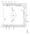
- FIG. 1 a rear end sectional view of scrap transfer apparatus located on a scrap carrier for use according to the present invention is shown.
- the scrap transfer apparatus typically forms a part of and is mounted on a trailer of the kind used for collection of scrap materials, the trailer being drawn by a vehicle.
- the scrap transfer apparatus may be incorporated directly into a vehicle.
- Either a vehicle or a trailer is hereafter referred to as a scrap carrier 2.
- a scrap carrier 2 is provided with a shell comprising at a first end, a first rear upright wall 6 with first and second side walls 8,10 extending therefrom.
- the side walls 8,10 are formed as walls upstanding from a load bed 4 of the scrap carrier.
- a releasable door 12 is provided to provide access to a storage volume defined by the first upright wall 6, the side walls 8,10 and the plane of the door 12 when in a closed position.
- the door is closed and scrap material loaded into the load space by dropping of the waste into the storage volume from above.
- the door 12 is opened by displacing it, by any suitable means, substantially vertically in channels (not shown) provided in the side walls.
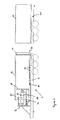
- the door is provided with an angled surface, angled such that an upper edge of the door surface is located rearwardly (to the left in Figure 2 ) of a lower edge of the door surface. This may be achieved by angling of the door or by providing an angled surface on an otherwise vertically disposed door.
- a first displaceable element 20 in the form of a carriage of generally U-shaped profile is provided in the storage volume.
- the carriage comprises a base 22 supported on a plurality of rollers 24 or the like and first and second upstanding side walls 26,28. Any suitable arrangement of rollers 24 may be used.
- the rollers 24 must be able to support the load of the first displaceable element when loaded with scrap.
- the carriage is also provided with an upstanding rear wall 30. This rear wall 30, as will become apparent, is provided with a cutaway or apertured portion.
- a front edge of the carriage is conveniently provided with a downwardly angled lip 32.
- the carriage extends slightly beyond the rear of the load bed 4 and accordingly a suitable cut-out portion is provided in the door 12 to allow the carriage to extend through the door when the door is in a closed position.
- the side walls 8,10 of the shell are each also conveniently provided with a plurality of vertical rollers 24, the plurality of rollers 24 extending along each side of the shell.
- the purpose of these rollers is to guide the first displaceable element 20 within the scrap carrier. Any suitable arrangement of the rollers may be utilised.
- the rollers may be disposed on the sides of the first displaceable element 20 instead of the side walls 8,10.
- the upper ends of the side walls 8,10 of the shell may be provided with inwardly directed flanges 16,18 to protect the vertical rollers 24 against damage from falling debris.
- the flanges 16,18 extend over and beyond the side walls 26,28 of the carriage.
- First displacement means 40 are located to the rear of the carriage. Conveniently such first displacement means 40 are secured to the upstanding rear wall 30 of the carriage, though they could be secured to other parts of the carriage. Preferably, the first displacement means 40 may take the form of one or more winch mechanisms, though other forms of displacement means may be utilised.
- a second displaceable element 60 in the form of a displaceable wall or panel is provided within the shell.
- the displaceable wall preferably has a surface angled forward, that is an upper edge is offset in a forward direction from a lower edge of the first displaceable wall.
- the displaceable wall is in a first position located to the rear of the scrap carrier 2 and may be displaced by a second displacement means 70 within the volume defined by the first displaceable element 20 without coming into contact with the first displaceable element 20.
- the displaceable wall extends substantially within an area defined by a section of the first displaceable element 20.
- the second displaceable element 60 or displaceable wall is supported in relation to the first displaceable element 20 by a wheeled structure 62.
- wheeled structure 62 aids relative movement between the first and second displaceable elements 20,60 while maintaining the orientation of the second displaceable element 60 with respect to the first displaceable element 20.
- the second displacement means 70 comprises a ram or piston, such as a double acting multistage ram.
- a hydraulic or pneumatic arrangement is preferred.
- the second displaceable element 60 is as noted above located in a rest position at or toward one end of the carriage. Accordingly, it is necessary for the second displacement means 70 to extend through or around the upstanding rear wall 30 of the carriage.
- the second displacement means 70 acts between the rear wall 6 of the shell and the second displaceable element 60.
- a further wall 72 is provided to the rear of the shell and the second displacement means 70 extends through the rear shell wall 6 and acts between the further wall 72 and the second displaceable element 60.
- an upper portion of the shell between the rear shell wall 6 and the first position of the second displaceable element 60 is provided with a cover (not shown) in order to avoid damage by falling debris such as scrap metal.
- the cover extends behind the rear shell wall 6 to the further wall 72 to protect the first (and second displacement) means from falling debris.
- the first displacement element 20 is releasably coupled to the second displaceable element 60 by any suitable means.
- pins 66 shown in Figure 1 , located to the rear of the rear upstanding wall 30 of the first displaceable element 20 located behind the second displaceable member 60
- receiving apertures formed at the free ends of arms 68 Figures 2 to 6
- the pins 66 may be automatically removed and reinserted to releasably connect or couple the first displacement element 20 and the second displaceable element 60 together.
- the scrap carrier is loaded through the upper opening with scrap material by use of known means such as a teleporter. It is an advantage of the angled surfaces of the second displaceable element 60 and the door 12 that the deposited scrap will tend to form a stable heap on the first displaceable element 20.
- a stable heap is one in which when the door 12 is opened, the scrap does not fall or otherwise run off the heap.
- the scrap carrier When it is desired to transfer the loaded scrap, the scrap carrier is aligned with a transport container 100 located on a transport container carrier 102.
- the door 12 is raised.
- the second displacement means 70 are actuated to drive the second displaceable element 60 from the rear of the shell to or slightly beyond the front of the shell.
- the second displacement means 70 also causes the first displaceable element 20 and the scrap loaded thereon to be moved into the transport container 100 ( Figure 4 ).
- an operator With the second displaceable element 60 maintained in an advanced position, to hold the scrap against axial displacement, an operator then causes the first and second displaceable elements to be uncoupled, that is in the illustrated embodiment the pins 66 are caused to be withdrawn from the arms 68. This may be achieved by any suitable means. The user then operates the first displacement means 40 to withdraw the first displaceable element 20.
- the first displaceable element 20 is readily pulled from beneath the scrap, thereby depositing the scrap in the transport container 100 ( Figure 5 ).
- the vertical rollers 14 guide the travel of the first displacement element between the side walls 8,10. The scrap is held in position within the transport container 100 during this operation by the second displaceable element 60.
- the second displacement means 70 is actuated to withdraw the second displaceable element 60 to its initial position.
- a third displacement means 74 may be used in addition to the second displacement means 70 to withdraw the second displaceable element 60.
- the third displacement means 74 comprises one or more winch mechanisms located between the further wall 72 and the first displaceable element 20.
- the rear door 12 may then be returned, by any suitable means, to its closed position. Thereafter the scrap carrier 2 and the transport container carrier 102 may be separated from one another.
- Each of the scrap carrier 2 and transport container carrier 102 are provided with self levelling air valves such that the levels of the scrap carrier and transport container carrier are maintained with respect to one another during transfer of the load.
Landscapes
- Engineering & Computer Science (AREA)
- Mechanical Engineering (AREA)
- Transportation (AREA)
- Refuse Collection And Transfer (AREA)
Applications Claiming Priority (1)
| Application Number | Priority Date | Filing Date | Title |
|---|---|---|---|
| GB0709540A GB0709540D0 (en) | 2007-05-18 | 2007-05-18 | Improved scrap transfer |
Publications (1)
| Publication Number | Publication Date |
|---|---|
| EP1992521A1 true EP1992521A1 (fr) | 2008-11-19 |
Family
ID=38234654
Family Applications (1)
| Application Number | Title | Priority Date | Filing Date |
|---|---|---|---|
| EP08251747A Withdrawn EP1992521A1 (fr) | 2007-05-18 | 2008-05-19 | Transfert de matériel |
Country Status (2)
| Country | Link |
|---|---|
| EP (1) | EP1992521A1 (fr) |
| GB (1) | GB0709540D0 (fr) |
Cited By (3)
| Publication number | Priority date | Publication date | Assignee | Title |
|---|---|---|---|---|
| WO2012102934A1 (fr) * | 2011-01-25 | 2012-08-02 | Lukesic Darrell Louis | Ensemble de chargement pour conteneur de réception |
| EP3697707A1 (fr) * | 2017-10-20 | 2020-08-26 | Dücker Fördertechnik GmbH | Chargement frontal entièrement automatisé d'un poids lourd à l'aide d'un chariot transporteur |
| US11866074B2 (en) | 2021-04-19 | 2024-01-09 | Shiloh Williams | Belly dump trailer with conveyors for moving material |
Citations (3)
| Publication number | Priority date | Publication date | Assignee | Title |
|---|---|---|---|---|
| EP0241231A2 (fr) * | 1986-04-03 | 1987-10-14 | Nor-Wood Enterprises | Machines à former des balles |
| US6632066B1 (en) * | 1999-09-06 | 2003-10-14 | Koshiji Kinzoku Co., Ltd. | Carrying and loading/unloading apparatus |
| US20060285949A1 (en) * | 2004-10-12 | 2006-12-21 | Nathan Frankel | Container support for loading transport containers and loading assembly incorporating same |
-
2007
- 2007-05-18 GB GB0709540A patent/GB0709540D0/en not_active Ceased
-
2008
- 2008-05-19 EP EP08251747A patent/EP1992521A1/fr not_active Withdrawn
Patent Citations (3)
| Publication number | Priority date | Publication date | Assignee | Title |
|---|---|---|---|---|
| EP0241231A2 (fr) * | 1986-04-03 | 1987-10-14 | Nor-Wood Enterprises | Machines à former des balles |
| US6632066B1 (en) * | 1999-09-06 | 2003-10-14 | Koshiji Kinzoku Co., Ltd. | Carrying and loading/unloading apparatus |
| US20060285949A1 (en) * | 2004-10-12 | 2006-12-21 | Nathan Frankel | Container support for loading transport containers and loading assembly incorporating same |
Cited By (3)
| Publication number | Priority date | Publication date | Assignee | Title |
|---|---|---|---|---|
| WO2012102934A1 (fr) * | 2011-01-25 | 2012-08-02 | Lukesic Darrell Louis | Ensemble de chargement pour conteneur de réception |
| EP3697707A1 (fr) * | 2017-10-20 | 2020-08-26 | Dücker Fördertechnik GmbH | Chargement frontal entièrement automatisé d'un poids lourd à l'aide d'un chariot transporteur |
| US11866074B2 (en) | 2021-04-19 | 2024-01-09 | Shiloh Williams | Belly dump trailer with conveyors for moving material |
Also Published As
| Publication number | Publication date |
|---|---|
| GB0709540D0 (en) | 2007-06-27 |
Similar Documents
| Publication | Publication Date | Title |
|---|---|---|
| US6224317B1 (en) | Front end loader adapter | |
| US5562390A (en) | Detachable truck body and handling mechanism | |
| US5829946A (en) | Detachable truck body and handling mechanism | |
| US5931628A (en) | Manual/automated side loader | |
| CA2150606C (fr) | Contenant a parois extensibles et methode | |
| US11117741B2 (en) | Object handling device and method | |
| US11383942B1 (en) | Container packer system and method | |
| EP1799599B1 (fr) | Ensemble de chargement pour conteneurs de transport | |
| WO1991000231A1 (fr) | Vehicule de collecte d'ordures | |
| US6854949B2 (en) | Refuse collection vehicle with pendular packing device and refuse ejection system | |
| US20060177294A1 (en) | Portable and stowable ramp and equipment storage system for pickup trucks | |
| US4934896A (en) | Refuse collection apparatus and method | |
| US7066705B1 (en) | Rear loader collection vehicle with detachable container | |
| US7886660B1 (en) | System and trash receptacle for collecting and compacting trash | |
| US10322874B1 (en) | Dumpster handling device and method | |
| US5938393A (en) | Container vehicle with loading means | |
| US5368436A (en) | Method for transporting waste material | |
| CN114030793B (zh) | 一种分体式垃圾压缩站及系统 | |
| US8033774B2 (en) | Secure rear-loading material handling apparatus system | |
| CN101304898A (zh) | 负载运送箱体 | |
| JPH0977207A (ja) | 廃棄物の輸送方法およびその輸送に用いるコンテナの構造 | |
| US20060072993A1 (en) | Refuse collection system and method | |
| US20130287541A1 (en) | Trunnion bar restraining system for rear loading garbage trucks | |
| CA3040401C (fr) | Dispositif et procede de manipulation de bennes a ordures | |
| CA2323471C (fr) | Adaptateur pour benne a chargement frontal |
Legal Events
| Date | Code | Title | Description |
|---|---|---|---|
| PUAI | Public reference made under article 153(3) epc to a published international application that has entered the european phase |
Free format text: ORIGINAL CODE: 0009012 |
|
| AK | Designated contracting states |
Kind code of ref document: A1 Designated state(s): AT BE BG CH CY CZ DE DK EE ES FI FR GB GR HR HU IE IS IT LI LT LU LV MC MT NL NO PL PT RO SE SI SK TR |
|
| AX | Request for extension of the european patent |
Extension state: AL BA MK RS |
|
| RAP1 | Party data changed (applicant data changed or rights of an application transferred) |
Owner name: BAYLEY, JOHN |
|
| RIN1 | Information on inventor provided before grant (corrected) |
Inventor name: BAYLEY, JOHN |
|
| AKX | Designation fees paid | ||
| REG | Reference to a national code |
Ref country code: DE Ref legal event code: 8566 |
|
| STAA | Information on the status of an ep patent application or granted ep patent |
Free format text: STATUS: THE APPLICATION IS DEEMED TO BE WITHDRAWN |
|
| 18D | Application deemed to be withdrawn |
Effective date: 20090520 |