EP1992536A2 - Procédé de limitation du moment d'entrée sur une unité de boîte de vitesse et système de commande - Google Patents
Procédé de limitation du moment d'entrée sur une unité de boîte de vitesse et système de commande Download PDFInfo
- Publication number
- EP1992536A2 EP1992536A2 EP08008245A EP08008245A EP1992536A2 EP 1992536 A2 EP1992536 A2 EP 1992536A2 EP 08008245 A EP08008245 A EP 08008245A EP 08008245 A EP08008245 A EP 08008245A EP 1992536 A2 EP1992536 A2 EP 1992536A2
- Authority
- EP
- European Patent Office
- Prior art keywords
- power
- generator
- combustion engine
- internal combustion
- torque
- Prior art date
- Legal status (The legal status is an assumption and is not a legal conclusion. Google has not performed a legal analysis and makes no representation as to the accuracy of the status listed.)
- Granted
Links
- 238000000034 method Methods 0.000 title claims abstract description 23
- 230000005540 biological transmission Effects 0.000 title claims description 63
- 238000002485 combustion reaction Methods 0.000 claims abstract description 84
- 230000008859 change Effects 0.000 claims description 21
- 238000002347 injection Methods 0.000 claims description 10
- 239000007924 injection Substances 0.000 claims description 10
- 230000000454 anti-cipatory effect Effects 0.000 claims description 6
- 238000013461 design Methods 0.000 claims description 5
- 238000012937 correction Methods 0.000 claims description 3
- 230000001419 dependent effect Effects 0.000 claims description 2
- 230000000875 corresponding effect Effects 0.000 description 14
- 230000009467 reduction Effects 0.000 description 8
- 238000010586 diagram Methods 0.000 description 7
- 230000001133 acceleration Effects 0.000 description 6
- 239000000243 solution Substances 0.000 description 4
- 238000004364 calculation method Methods 0.000 description 3
- 238000004891 communication Methods 0.000 description 3
- 230000001276 controlling effect Effects 0.000 description 3
- 230000001186 cumulative effect Effects 0.000 description 3
- 238000001514 detection method Methods 0.000 description 3
- 238000011156 evaluation Methods 0.000 description 3
- 230000008569 process Effects 0.000 description 3
- 230000035484 reaction time Effects 0.000 description 3
- 230000001105 regulatory effect Effects 0.000 description 3
- 230000008901 benefit Effects 0.000 description 2
- 238000011161 development Methods 0.000 description 2
- 230000008878 coupling Effects 0.000 description 1
- 238000010168 coupling process Methods 0.000 description 1
- 238000005859 coupling reaction Methods 0.000 description 1
- 230000002950 deficient Effects 0.000 description 1
- 230000003111 delayed effect Effects 0.000 description 1
- 230000000694 effects Effects 0.000 description 1
- 239000000446 fuel Substances 0.000 description 1
- 238000010438 heat treatment Methods 0.000 description 1
- 230000002427 irreversible effect Effects 0.000 description 1
- 238000004519 manufacturing process Methods 0.000 description 1
- 238000005259 measurement Methods 0.000 description 1
- 230000009347 mechanical transmission Effects 0.000 description 1
- 238000004513 sizing Methods 0.000 description 1
- 238000013519 translation Methods 0.000 description 1
- 230000014616 translation Effects 0.000 description 1
- 238000012795 verification Methods 0.000 description 1
Images

Classifications
-
- B—PERFORMING OPERATIONS; TRANSPORTING
- B60—VEHICLES IN GENERAL
- B60W—CONJOINT CONTROL OF VEHICLE SUB-UNITS OF DIFFERENT TYPE OR DIFFERENT FUNCTION; CONTROL SYSTEMS SPECIALLY ADAPTED FOR HYBRID VEHICLES; ROAD VEHICLE DRIVE CONTROL SYSTEMS FOR PURPOSES NOT RELATED TO THE CONTROL OF A PARTICULAR SUB-UNIT
- B60W10/00—Conjoint control of vehicle sub-units of different type or different function
- B60W10/04—Conjoint control of vehicle sub-units of different type or different function including control of propulsion units
- B60W10/06—Conjoint control of vehicle sub-units of different type or different function including control of propulsion units including control of combustion engines
-
- B—PERFORMING OPERATIONS; TRANSPORTING
- B60—VEHICLES IN GENERAL
- B60W—CONJOINT CONTROL OF VEHICLE SUB-UNITS OF DIFFERENT TYPE OR DIFFERENT FUNCTION; CONTROL SYSTEMS SPECIALLY ADAPTED FOR HYBRID VEHICLES; ROAD VEHICLE DRIVE CONTROL SYSTEMS FOR PURPOSES NOT RELATED TO THE CONTROL OF A PARTICULAR SUB-UNIT
- B60W10/00—Conjoint control of vehicle sub-units of different type or different function
- B60W10/04—Conjoint control of vehicle sub-units of different type or different function including control of propulsion units
- B60W10/08—Conjoint control of vehicle sub-units of different type or different function including control of propulsion units including control of electric propulsion units, e.g. motors or generators
-
- B—PERFORMING OPERATIONS; TRANSPORTING
- B60—VEHICLES IN GENERAL
- B60W—CONJOINT CONTROL OF VEHICLE SUB-UNITS OF DIFFERENT TYPE OR DIFFERENT FUNCTION; CONTROL SYSTEMS SPECIALLY ADAPTED FOR HYBRID VEHICLES; ROAD VEHICLE DRIVE CONTROL SYSTEMS FOR PURPOSES NOT RELATED TO THE CONTROL OF A PARTICULAR SUB-UNIT
- B60W10/00—Conjoint control of vehicle sub-units of different type or different function
- B60W10/30—Conjoint control of vehicle sub-units of different type or different function including control of auxiliary equipment, e.g. air-conditioning compressors or oil pumps
-
- B—PERFORMING OPERATIONS; TRANSPORTING
- B60—VEHICLES IN GENERAL
- B60W—CONJOINT CONTROL OF VEHICLE SUB-UNITS OF DIFFERENT TYPE OR DIFFERENT FUNCTION; CONTROL SYSTEMS SPECIALLY ADAPTED FOR HYBRID VEHICLES; ROAD VEHICLE DRIVE CONTROL SYSTEMS FOR PURPOSES NOT RELATED TO THE CONTROL OF A PARTICULAR SUB-UNIT
- B60W30/00—Purposes of road vehicle drive control systems not related to the control of a particular sub-unit, e.g. of systems using conjoint control of vehicle sub-units
- B60W30/18—Propelling the vehicle
- B60W30/188—Controlling power parameters of the driveline, e.g. determining the required power
-
- B—PERFORMING OPERATIONS; TRANSPORTING
- B60—VEHICLES IN GENERAL
- B60W—CONJOINT CONTROL OF VEHICLE SUB-UNITS OF DIFFERENT TYPE OR DIFFERENT FUNCTION; CONTROL SYSTEMS SPECIALLY ADAPTED FOR HYBRID VEHICLES; ROAD VEHICLE DRIVE CONTROL SYSTEMS FOR PURPOSES NOT RELATED TO THE CONTROL OF A PARTICULAR SUB-UNIT
- B60W50/00—Details of control systems for road vehicle drive control not related to the control of a particular sub-unit, e.g. process diagnostic or vehicle driver interfaces
- B60W50/0097—Predicting future conditions
-
- B—PERFORMING OPERATIONS; TRANSPORTING
- B60—VEHICLES IN GENERAL
- B60L—PROPULSION OF ELECTRICALLY-PROPELLED VEHICLES; SUPPLYING ELECTRIC POWER FOR AUXILIARY EQUIPMENT OF ELECTRICALLY-PROPELLED VEHICLES; ELECTRODYNAMIC BRAKE SYSTEMS FOR VEHICLES IN GENERAL; MAGNETIC SUSPENSION OR LEVITATION FOR VEHICLES; MONITORING OPERATING VARIABLES OF ELECTRICALLY-PROPELLED VEHICLES; ELECTRIC SAFETY DEVICES FOR ELECTRICALLY-PROPELLED VEHICLES
- B60L2200/00—Type of vehicles
- B60L2200/26—Rail vehicles
-
- B—PERFORMING OPERATIONS; TRANSPORTING
- B60—VEHICLES IN GENERAL
- B60L—PROPULSION OF ELECTRICALLY-PROPELLED VEHICLES; SUPPLYING ELECTRIC POWER FOR AUXILIARY EQUIPMENT OF ELECTRICALLY-PROPELLED VEHICLES; ELECTRODYNAMIC BRAKE SYSTEMS FOR VEHICLES IN GENERAL; MAGNETIC SUSPENSION OR LEVITATION FOR VEHICLES; MONITORING OPERATING VARIABLES OF ELECTRICALLY-PROPELLED VEHICLES; ELECTRIC SAFETY DEVICES FOR ELECTRICALLY-PROPELLED VEHICLES
- B60L2240/00—Control parameters of input or output; Target parameters
- B60L2240/40—Drive Train control parameters
- B60L2240/42—Drive Train control parameters related to electric machines
- B60L2240/423—Torque
-
- B—PERFORMING OPERATIONS; TRANSPORTING
- B60—VEHICLES IN GENERAL
- B60W—CONJOINT CONTROL OF VEHICLE SUB-UNITS OF DIFFERENT TYPE OR DIFFERENT FUNCTION; CONTROL SYSTEMS SPECIALLY ADAPTED FOR HYBRID VEHICLES; ROAD VEHICLE DRIVE CONTROL SYSTEMS FOR PURPOSES NOT RELATED TO THE CONTROL OF A PARTICULAR SUB-UNIT
- B60W2540/00—Input parameters relating to occupants
- B60W2540/10—Accelerator pedal position
-
- B—PERFORMING OPERATIONS; TRANSPORTING
- B60—VEHICLES IN GENERAL
- B60W—CONJOINT CONTROL OF VEHICLE SUB-UNITS OF DIFFERENT TYPE OR DIFFERENT FUNCTION; CONTROL SYSTEMS SPECIALLY ADAPTED FOR HYBRID VEHICLES; ROAD VEHICLE DRIVE CONTROL SYSTEMS FOR PURPOSES NOT RELATED TO THE CONTROL OF A PARTICULAR SUB-UNIT
- B60W2710/00—Output or target parameters relating to a particular sub-units
- B60W2710/06—Combustion engines, Gas turbines
- B60W2710/0616—Position of fuel or air injector
-
- B—PERFORMING OPERATIONS; TRANSPORTING
- B60—VEHICLES IN GENERAL
- B60W—CONJOINT CONTROL OF VEHICLE SUB-UNITS OF DIFFERENT TYPE OR DIFFERENT FUNCTION; CONTROL SYSTEMS SPECIALLY ADAPTED FOR HYBRID VEHICLES; ROAD VEHICLE DRIVE CONTROL SYSTEMS FOR PURPOSES NOT RELATED TO THE CONTROL OF A PARTICULAR SUB-UNIT
- B60W2710/00—Output or target parameters relating to a particular sub-units
- B60W2710/06—Combustion engines, Gas turbines
- B60W2710/0666—Engine torque
-
- B—PERFORMING OPERATIONS; TRANSPORTING
- B60—VEHICLES IN GENERAL
- B60W—CONJOINT CONTROL OF VEHICLE SUB-UNITS OF DIFFERENT TYPE OR DIFFERENT FUNCTION; CONTROL SYSTEMS SPECIALLY ADAPTED FOR HYBRID VEHICLES; ROAD VEHICLE DRIVE CONTROL SYSTEMS FOR PURPOSES NOT RELATED TO THE CONTROL OF A PARTICULAR SUB-UNIT
- B60W2710/00—Output or target parameters relating to a particular sub-units
- B60W2710/08—Electric propulsion units
- B60W2710/083—Torque
-
- B—PERFORMING OPERATIONS; TRANSPORTING
- B60—VEHICLES IN GENERAL
- B60W—CONJOINT CONTROL OF VEHICLE SUB-UNITS OF DIFFERENT TYPE OR DIFFERENT FUNCTION; CONTROL SYSTEMS SPECIALLY ADAPTED FOR HYBRID VEHICLES; ROAD VEHICLE DRIVE CONTROL SYSTEMS FOR PURPOSES NOT RELATED TO THE CONTROL OF A PARTICULAR SUB-UNIT
- B60W2710/00—Output or target parameters relating to a particular sub-units
- B60W2710/10—Change speed gearings
-
- B—PERFORMING OPERATIONS; TRANSPORTING
- B60—VEHICLES IN GENERAL
- B60W—CONJOINT CONTROL OF VEHICLE SUB-UNITS OF DIFFERENT TYPE OR DIFFERENT FUNCTION; CONTROL SYSTEMS SPECIALLY ADAPTED FOR HYBRID VEHICLES; ROAD VEHICLE DRIVE CONTROL SYSTEMS FOR PURPOSES NOT RELATED TO THE CONTROL OF A PARTICULAR SUB-UNIT
- B60W2710/00—Output or target parameters relating to a particular sub-units
- B60W2710/10—Change speed gearings
- B60W2710/1022—Input torque
-
- Y—GENERAL TAGGING OF NEW TECHNOLOGICAL DEVELOPMENTS; GENERAL TAGGING OF CROSS-SECTIONAL TECHNOLOGIES SPANNING OVER SEVERAL SECTIONS OF THE IPC; TECHNICAL SUBJECTS COVERED BY FORMER USPC CROSS-REFERENCE ART COLLECTIONS [XRACs] AND DIGESTS
- Y02—TECHNOLOGIES OR APPLICATIONS FOR MITIGATION OR ADAPTATION AGAINST CLIMATE CHANGE
- Y02T—CLIMATE CHANGE MITIGATION TECHNOLOGIES RELATED TO TRANSPORTATION
- Y02T10/00—Road transport of goods or passengers
- Y02T10/60—Other road transportation technologies with climate change mitigation effect
- Y02T10/64—Electric machine technologies in electromobility
Definitions
- the invention relates to a method for limiting the input torque of a gear unit input torque, in detail with the features of the preamble of claim 1; and a control system for carrying out the method.
- a method of controlling the input torque at an input of a transmission assembly in a drive system for vehicles, comprising an internal combustion engine, a transmission assembly coupleable thereto, and a generator coupled to the internal combustion engine electrical machine, is also from the document DE 101 37 475 previously known. This is characterized by the fact that the internal combustion engine with respect to the theoretically possible power output can absorb the maximum of the generator recordable power and at the same time permissible at the input of the transmission unit maximum absorbable torque, the maximum torque over a certain speed range should be possible and thus the maximum defines possible transmissible power via the transmission unit.
- an actuator such as accelerator pedal
- a target value for the output to the internal combustion engine power is specified.
- the maximum allowable from the transmission input shaft or at the transmission input recordable torque is thereby corrected depending on the current actual speed of the internal combustion engine and the generator recordable torque of this setpoint to the effect that of the internal combustion engine, taking into account the currently required torque for the generator the torque that can be transmitted to the gear unit does not exceed the maximum permissible input torque of the gear unit.
- the currently required generator torque is determined at a corresponding speed of the internal combustion engine and processed in a control device as a function of the current drawn from the electrical system.
- the invention is therefore based on the object, a method for controlling and / or regulating the input torque in a transmission unit in a drive train or drive system of the type mentioned in such a way that on the one hand always according to the driver's request for acceleration and deceleration of this driver's desire on the output, d. H. can be provided to the drive train via the gear unit, regardless of the required power to be provided for the generator. Due to the cumulative reaction times, temporary overloads must be prevented or eliminated.
- the device implementation should be characterized by a low design, manufacturing and control engineering effort.
- the method for controlling the input torque at an input of a gear unit in a drive system for vehicles comprising an internal combustion engine, a coupled with this transmission unit and a combustion engine coupled, acting as a generator electric machine, characterized in that the internal combustion engine with respect to the theoretically possible Power output each of which can be absorbed by the generator maximum power and at the same time the maximum allowable at the entrance of the transmission unit recordable torque, the maximum torque for a given speed range is possible and thus defines the maximum possible transmissible via the transmission unit power.
- an actuator such as accelerator pedal
- the transmission input shaft or at the transmission input recordable torque is thereby corrected depending on the current actual speed of the internal combustion engine and the recordable by the generator torque of this setpoint that of the internal combustion engine, taking into account the currently required torque for the generator M generator deliverable Torque on the gear unit does not exceed the maximum permissible input torque of the gear unit.
- the currently required generator torque is determined at a corresponding speed of the internal combustion engine and processed in a control device as a function of the current I removed from the electrical system.
- the current injection quantity is determined, which can be closed on the currently presentable from the internal combustion engine power and thus the present at least proportional to the input torque of the transmission unit torque of the internal combustion engine M M can be formed.
- a specific target torque M target for the transmission unit which inventively determined taking into account the determined via an anticipatory torque control chargeable generator torque a deliverable from the internal combustion engine total torque. If the input torque is smaller than the maximum permissible input torque, the driver's request is correspondingly implemented on the power actuator of the internal combustion engine.
- the input torque determined in this case is greater than or equal to the maximum permissible input torque
- a reduction in the power deliverable by the internal combustion engine takes place at this rotational speed, so that the maximum permissible input torque is not exceeded, ie the setpoint torque to be introduced at the transmission input is now set equal to the maximum permissible input torque so the driver's request is not direct is implemented.
- the actual setpoint specification is adjusted in the manner of a control loop by the manipulated variable is changed accordingly on the power actuator of the internal combustion engine, however, the maximum permissible input torque to the transmission unit may not be exceeded.
- the solution according to the invention has the advantage that on the one hand by the concrete limitability of the input torque of the gear unit this can almost always or only slightly delayed in time according to the driver can be supplied with power and further a dimensioning of the transmission only in terms of the predetermined limits for the input torque must be done and not on an unlimited moment peak, so that compared to a conventional design of the gear unit cost savings can be recorded.
- Other significant advantages are due to the avoidance of torque peaks and thus a lower load in a much longer life and no limitation of starting and permanent stiffness.
- the use of anticipatory torque control allows the avoidance of temporary overloads.
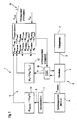
- FIG. 1 illustrates in a simplified schematic representation of a block diagram of a control system 1 for limiting the invention of an input torque of a gear unit 2 in a drive train 3, as it can be used in particular in rail vehicles.
- Input moment is therefore understood to mean the torque introduced during power transmission from the drive machine, for example in the form of an internal combustion engine 4 to the output at the input E into the transmission unit.
- the drive train 3 comprises a drive machine in the form of an internal combustion engine 4, which is used directly or via further transmission elements with the gear unit 2 in drive connection to the drive, for example when used in rail vehicles of axles or wheels.
- a generator 5 With the internal combustion engine 4 mechanically and usually rotatably coupled is a generator 5, which is used to generate the required electrical power, which is provided via a vehicle electrical system 14 available.
- the power generated by the internal combustion engine 4 is thus divided, a first power component, which usually also forms the main power component, serves to drive the vehicle in which the drive train 3 is integrated, the second power component is used to supply the on-board electronics for use in vehicles , used in particular rail vehicles.
- the internal combustion engine 4 is interpreted in terms of the performance characteristics that the depositable of their total power P total of the sum of the maximum, from the generator recordable power P generator max and the maximum permissible, from the transmission unit 2, in particular at the transmission input E recordable or initiated in this power P gear max corresponds, ie, that while supplying the drive train 3 and the electrical system with power for both systems respectively maximum possible power can be provided.
- the power required to be taken into account by the generator is not considered to be the value P generator setpoint , but an inventively determined value P generator-chargeable via an anticipatory torque control, which is calculated from P generator setpoint and the current actual value, taking into account the determined over time change behavior.
- the total power P total target output by the internal combustion engine 4 thus corresponds to the sum of the generator P power to be supplied to the generator and the power to be supplied to the drive train P A target .
- the size of the individual performance shares can vary. This moves for the generator between 0 ⁇ P generator-chargeable ⁇ P generator max .
- the first power component which as a rule is present as the main power component, may be in the range of 0 ⁇ P A target ⁇ P gear max .
- the deliverable by the internal combustion engine total power P total target is accordingly in a range between 0 ⁇ P total target ⁇ P total max .
- P generator target is detected with means for detecting at least one of the output current from the generator 5 at least indirectly characterizing magnitude of the output current from the generator 5 I and read in a control device 6 or as Input signal supplied.
- the means for detecting at least one of the current I output by the generator 5 at least indirectly characterizing size are denoted by 7 and serve to generate a signal which is applied to an input 8 of the control device 6 and can be recorded.
- the coupling between the control device 6 and the means for detecting the current 7 can be wireless or via corresponding other communication means, for example, a data communication network.
- the current rotational speed n M of the internal combustion engine 4 or a variable that at least indirectly characterizes it is detected.
- This can either be detected via a special device for detecting a, the speed n M of the internal combustion engine at least indirectly characterizing size 9, said device in this case, not shown, directly to the control device 6 and an input of this, for example, the input 7 is coupled in serial data transmission or an additional additional input.
- Another possibility is to read this variable, which is already determined for other control processes, for example, via a control unit 10, which in any case has the function of a control device, of the internal combustion engine 4 and to supply it to the control device 6 of the control system 1 for limiting the input torque.
- the control device 6 acts essentially as an evaluation and allocation device and is usually in the form of a control unit executed. However, it is also conceivable that the control device 6 consists of a plurality of individual components, which are, however, linked with respect to their function with each other and thus form a virtual control device.
- the characteristic can be stored in a diagram as assignment of individual operating points, in tabular form or merely as a mathematical link, from which knowledge of the current speed n M-is the internal combustion engine 4 and when determined, output from the generator current I is the generator torque M generator -ist can be determined.
- This current generator torque forms the moment that is currently or at a certain specific time from the generator 5 at a certain speed n M-Ist of the internal combustion engine recorded.
- information about the current fuel supply, in particular the injection quantity of the internal combustion engine is processed in the control system. This can for example be derived from a, the position of a power actuator of the internal combustion engine at least indirectly descriptive size.
- This assignment can also take place via an assignment device 12 in the control device 6.
- the characteristic can also be stored in the form of a characteristic diagram in a diagram, table form or else merely the mathematical relationship.
- To change the driving behavior can be made via a control element, for example in the form of an accelerator pedal 13 or another element, a desire for changing the available drive power or acceleration or deceleration of the vehicle.
- the actuation of the accelerator pedal is thereby converted into a signal for a, the driver's request after changing the driving condition at least indirectly descriptive size, from which a signal for the specification of a given by the internal combustion engine 4 power P M target is generated.
- the driver's request is modified so that for the time being the required torque M E transmission and thus the required power component P A target are set to the torque at the current actual rotational speed n M.
- each speed change of the internal combustion engine 4 shows corresponding effect, which is why a continuous comparison of the theoretically resulting input torque at the same driver's request and change the speed of the internal combustion engine n M- a rapid adjustment of the set power for the Powertrain to the actually required according to the driver's request.
- the maximum permissible input torque M E gearbox permitted by the theoretically determined value for the input torque is not exceeded, no limitation is necessary.
- the required total power resulting from the driver's request and the corresponding decrease in power from the electrical system and thus the provision of electric power via the generator 5 is set. From this size then the target value for the injection quantity as so-called Filling setpoint formed and the control device 10 of the internal combustion engine 4 is supplied, which causes a corresponding adjustment to the power actuator.
- the internal combustion engine torque M M-ist wherein the deliverable to the transmission unit torque M E gearbox max is not exceeded.
- the control device 6 can in this case be formed by a control device assigned to the transmission unit or another control device arranged arbitrarily in the vehicle, for example also by the drive control.
- the limitation of the input torque according to the invention can also be carried out by the control unit 10 of the internal combustion engine 4 with a corresponding configuration, this solution not being used by different manufacturers of the individual components.
- the auxiliary equipment management reports a change in the auxiliary power before it is actually carried out. With a shutdown of ancillary loads thus overloading is avoided.
- the engine power or the engine control setting can be changed to overload the combustion engine, for. B. idle, counteract.
- the ancillary power provided for taking into account the power P M-intended to be actually output by the internal combustion engine takes place via the actually chargeable ancillary power, ie P generator-receiving . This is calculated by the accessory management and the current at a time t requested auxiliary power measured and calculated.
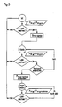
- the measurement of the current power is carried out as already described. From the requested power for the ancillaries P generator setpoint and the current auxiliary power P generator actual , the selection and calculation of the chargeable power P Generator-Anrechanbar is made, as in FIG. 2 shown.
- the requested ancillary power P generator setpoint is controlled by means of expiry machines, waiting times and takeover signals.
- the chargeable accessory power is set lower during the reduction by a defined value because the requested accessory power during the shutdown is inaccurate to determine.
- the current auxiliary power P generator latx is then used again, since the load change is completed. This procedure is in the FIG. 3 shown. This illustrates the functional sequence of the anticipatory torque controller as a function of the requested auxiliary power.
- P generator actual P Nagg- and the requested depending on the intended connection or disconnection of ancillaries specified auxiliary power
- P NAgg-requested P generator-requested the calculation of the chargeable power P generator-arechanbar made.
- This chargeable Power corresponds to the generator power P generator requested in determining the required total power. Depending on this value, the filling state or the injection quantity at the internal combustion engine is then changed.
- the assignment of the generator torque to the current and the engine torque to the injection quantity is subject to tolerances.
- a check of the calculated input torque of the transmission is carried out when the transmission unit is designed as a converter transmission in the converter gear of the transmission unit.
- the transmission unit is designed as a converter transmission in the converter gear of the transmission unit.
- the speed and the torque at the input of the transmission can thus be calculated from the speed and compared with the torque determined from the characteristic curves.
- the inventive method is verified according to a further development by an independent control algorithm.
- Two basic states are distinguished, the absolute overload and the overload profile.
- the duration of the overload is registered and the amount of the overload is divided into classes.
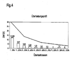
- the classification is exemplary based FIG. 4 in a time overload class diagram that characterizes the overload profile.
- FIG. 4 By analyzing this overload profile, conclusions can be drawn about the control function. It is in FIG. 4 exemplified such an overload profile.
- very large time shares are provided exclusively in the classes between 11 and 20 kW.
- the actual value detection of the ancillaries for example, by a tolerance or error of z. B. 15 kW is characterized. This means that 15 kW more are always reported than actually accepted.
Landscapes
- Engineering & Computer Science (AREA)
- Chemical & Material Sciences (AREA)
- Combustion & Propulsion (AREA)
- Transportation (AREA)
- Mechanical Engineering (AREA)
- Automation & Control Theory (AREA)
- Human Computer Interaction (AREA)
- Control Of Vehicle Engines Or Engines For Specific Uses (AREA)
- Control Of Transmission Device (AREA)
- Control Of Eletrric Generators (AREA)
- Structure Of Transmissions (AREA)
Applications Claiming Priority (1)
| Application Number | Priority Date | Filing Date | Title |
|---|---|---|---|
| DE102007022812A DE102007022812B4 (de) | 2007-05-15 | 2007-05-15 | Verfahren zur Begrenzung des Eingangsmoments an einer Getriebeeinheit und Steuerungssystem |
Publications (3)
| Publication Number | Publication Date |
|---|---|
| EP1992536A2 true EP1992536A2 (fr) | 2008-11-19 |
| EP1992536A3 EP1992536A3 (fr) | 2010-07-07 |
| EP1992536B1 EP1992536B1 (fr) | 2010-12-22 |
Family
ID=39496173
Family Applications (1)
| Application Number | Title | Priority Date | Filing Date |
|---|---|---|---|
| EP08008245A Not-in-force EP1992536B1 (fr) | 2007-05-15 | 2008-04-30 | Procédé de limitation du moment d'entrée sur une unité de boîte de vitesse et système de commande |
Country Status (3)
| Country | Link |
|---|---|
| EP (1) | EP1992536B1 (fr) |
| AT (1) | ATE492449T1 (fr) |
| DE (2) | DE102007022812B4 (fr) |
Cited By (2)
| Publication number | Priority date | Publication date | Assignee | Title |
|---|---|---|---|---|
| DE102012207086A1 (de) * | 2012-04-27 | 2013-10-31 | Continental Automotive Gmbh | Verfahren und Vorrichtung zur Steuerung eines Verbrennungsmotors |
| CN106132749A (zh) * | 2014-03-28 | 2016-11-16 | 奥迪股份公司 | 用于机动车的驱动系统 |
Families Citing this family (1)
| Publication number | Priority date | Publication date | Assignee | Title |
|---|---|---|---|---|
| DE102010002375B4 (de) * | 2010-02-26 | 2021-08-12 | Zf Friedrichshafen Ag | Verfahren zum Betreiben eines Fahrzeuges mit wenigstens einer Getriebeeinrichtung, einer Antriebsmaschine und wenigstens einer von der Antriebsmaschine antreibbaren Fahrzeugkomponente |
Citations (1)
| Publication number | Priority date | Publication date | Assignee | Title |
|---|---|---|---|---|
| DE10137475C1 (de) | 2001-08-02 | 2003-05-28 | Voith Turbo Kg | Verfahren zur Steuerung des Eingangsmoments an einer Getriebebaueinheit |
Family Cites Families (4)
| Publication number | Priority date | Publication date | Assignee | Title |
|---|---|---|---|---|
| JPS59192839A (ja) * | 1983-04-14 | 1984-11-01 | Yanmar Diesel Engine Co Ltd | 内燃機関の制御装置 |
| DE19932309A1 (de) * | 1999-07-10 | 2001-01-11 | Bosch Gmbh Robert | Verfahren und Vorrichtung zur Steuerung einer Antriebseinheit eines Fahrzeugs |
| US6336063B1 (en) * | 2000-10-31 | 2002-01-01 | Volvo Car Corporation | Method and arrangement in a hybrid vehicle for improving battery state-of-charge control and minimizing driver perceptible disturbances |
| GB2411739A (en) * | 2004-03-02 | 2005-09-07 | Bombardier Transp Gmbh | Method of limiting power from combustion motor of a vehicle |
-
2007
- 2007-05-15 DE DE102007022812A patent/DE102007022812B4/de not_active Expired - Fee Related
-
2008
- 2008-04-30 DE DE502008002041T patent/DE502008002041D1/de active Active
- 2008-04-30 AT AT08008245T patent/ATE492449T1/de active
- 2008-04-30 EP EP08008245A patent/EP1992536B1/fr not_active Not-in-force
Patent Citations (1)
| Publication number | Priority date | Publication date | Assignee | Title |
|---|---|---|---|---|
| DE10137475C1 (de) | 2001-08-02 | 2003-05-28 | Voith Turbo Kg | Verfahren zur Steuerung des Eingangsmoments an einer Getriebebaueinheit |
Cited By (3)
| Publication number | Priority date | Publication date | Assignee | Title |
|---|---|---|---|---|
| DE102012207086A1 (de) * | 2012-04-27 | 2013-10-31 | Continental Automotive Gmbh | Verfahren und Vorrichtung zur Steuerung eines Verbrennungsmotors |
| DE102012207086B4 (de) * | 2012-04-27 | 2020-12-03 | Vitesco Technologies GmbH | Verfahren, Vorrichtung und Computerprogrammprodukt zur Steuerung eines Verbrennungsmotors |
| CN106132749A (zh) * | 2014-03-28 | 2016-11-16 | 奥迪股份公司 | 用于机动车的驱动系统 |
Also Published As
| Publication number | Publication date |
|---|---|
| DE102007022812A1 (de) | 2008-11-20 |
| EP1992536A3 (fr) | 2010-07-07 |
| ATE492449T1 (de) | 2011-01-15 |
| DE102007022812B4 (de) | 2009-05-20 |
| DE502008002041D1 (de) | 2011-02-03 |
| EP1992536B1 (fr) | 2010-12-22 |
Similar Documents
| Publication | Publication Date | Title |
|---|---|---|
| DE102005021251B4 (de) | Koordinierte Nutz- und Motorbremsung für ein Hybridfahrzeug | |
| EP0944946B1 (fr) | Systeme de distribution d'energie dans un vehicule | |
| DE102005021250B4 (de) | Verfahren für den Unterspannungsschutz während des Motoranlassens | |
| DE102017211248B4 (de) | Verfahren zur Rekuperation von kinetischer Energie eines Hybridfahrzeuges, sowie Steuereinrichtung hierfür | |
| EP1992536B1 (fr) | Procédé de limitation du moment d'entrée sur une unité de boîte de vitesse et système de commande | |
| EP2033865B1 (fr) | Procédé de coordination de couple dynamique d'agrégats d'un entraînement hybride d'un véhicule et dispositif correspondant | |
| DE102005040783A1 (de) | Verfahren zur Steuerung einer Fahrzeug-Antriebseinheit | |
| WO2010004023A2 (fr) | Procédé de détection de l'état de charge d'une batterie de véhicule et commande électronique | |
| DE102005062870A1 (de) | Verfahren zur Überwachung von Mehrmotorenantrieben | |
| WO2020088818A1 (fr) | Procédé et appareil de commande d'entraînement servant à faire fonctionner au moins deux machines d'entraînement électriques en cas de variation de charge, et véhicule automobile comprenant un appareil de commande d'entraînement | |
| WO2015010951A1 (fr) | Procédé permettant d'accoupler au moins une source d'énergie secondaire à un réseau d'alimentation en énergie, en particulier un réseau de bord d'un véhicule | |
| EP3036141B1 (fr) | Commande d'entraînement de véhicule automobile | |
| DE102007013253A1 (de) | Verfahren und Vorrichtung zum Betreiben einer Antriebseinheit | |
| DE102022202956B4 (de) | Hysterese basierte Ansteuerung eines Fahrzeugantriebs mit abwechselndem Freilauf- und Kurzschlusszustand im Fehlerfall | |
| DE10137475C1 (de) | Verfahren zur Steuerung des Eingangsmoments an einer Getriebebaueinheit | |
| EP1201504B1 (fr) | Méthode pour la régulation de la distribution d'énergie pour des équipements électriques dans un véhicule automobile | |
| DE102006008365B4 (de) | Verfahren zur Regelung der Leistungsabgabe an die Räder eines Kraftfahrzeuges sowie Kraftfahrzeug | |
| EP1188601B1 (fr) | Méthode de commande et de limitation du couple d'entrée d'une boíte de vitesses pendant le démarrage d'un véhicule | |
| EP1537315B1 (fr) | Procede et dispositif pour commander un ensemble moteur | |
| EP4344921B1 (fr) | Procédé de commande d'une chaîne cinématique dans un véhicule hybride et véhicule hybride | |
| DE102024206481B3 (de) | Verfahren zum Betreiben eines Antriebsstrangs, elektrifizierter Antriebsstrang und Arbeitsmaschine | |
| DE102017203992B4 (de) | Hybridantrieb mit Batterieschutz | |
| AT509441B1 (de) | Regelung von zwei generatoren eines kraftfahrzeug-stromkreises | |
| EP1392544B1 (fr) | Procede de commande de distributeurs d'energie dans des systemes d'entrainement et systeme d'entrainement | |
| EP4124513A1 (fr) | Dispositif d'alimentation électrique, ainsi que engin de travail agricole doté d'un tel dispositif d'alimentation |
Legal Events
| Date | Code | Title | Description |
|---|---|---|---|
| PUAI | Public reference made under article 153(3) epc to a published international application that has entered the european phase |
Free format text: ORIGINAL CODE: 0009012 |
|
| AK | Designated contracting states |
Kind code of ref document: A2 Designated state(s): AT BE BG CH CY CZ DE DK EE ES FI FR GB GR HR HU IE IS IT LI LT LU LV MC MT NL NO PL PT RO SE SI SK TR |
|
| AX | Request for extension of the european patent |
Extension state: AL BA MK RS |
|
| PUAL | Search report despatched |
Free format text: ORIGINAL CODE: 0009013 |
|
| AK | Designated contracting states |
Kind code of ref document: A3 Designated state(s): AT BE BG CH CY CZ DE DK EE ES FI FR GB GR HR HU IE IS IT LI LT LU LV MC MT NL NO PL PT RO SE SI SK TR |
|
| AX | Request for extension of the european patent |
Extension state: AL BA MK RS |
|
| GRAP | Despatch of communication of intention to grant a patent |
Free format text: ORIGINAL CODE: EPIDOSNIGR1 |
|
| 17P | Request for examination filed |
Effective date: 20100611 |
|
| RIC1 | Information provided on ipc code assigned before grant |
Ipc: B60W 10/08 20060101ALI20100701BHEP Ipc: B60W 30/18 20060101ALI20100701BHEP Ipc: B60W 10/30 20060101ALI20100701BHEP Ipc: B60W 10/06 20060101AFI20100701BHEP |
|
| GRAS | Grant fee paid |
Free format text: ORIGINAL CODE: EPIDOSNIGR3 |
|
| GRAA | (expected) grant |
Free format text: ORIGINAL CODE: 0009210 |
|
| AK | Designated contracting states |
Kind code of ref document: B1 Designated state(s): AT BE BG CH CY CZ DE DK EE ES FI FR GB GR HR HU IE IS IT LI LT LU LV MC MT NL NO PL PT RO SE SI SK TR |
|
| REG | Reference to a national code |
Ref country code: GB Ref legal event code: FG4D Free format text: NOT ENGLISH |
|
| REG | Reference to a national code |
Ref country code: CH Ref legal event code: EP |
|
| REG | Reference to a national code |
Ref country code: IE Ref legal event code: FG4D |
|
| REF | Corresponds to: |
Ref document number: 502008002041 Country of ref document: DE Date of ref document: 20110203 Kind code of ref document: P |
|
| REG | Reference to a national code |
Ref country code: DE Ref legal event code: R096 Ref document number: 502008002041 Country of ref document: DE Effective date: 20110203 |
|
| AKX | Designation fees paid |
Designated state(s): AT BE BG CH CY CZ DE DK EE ES FI FR GB GR HR HU IE IS IT LI LT LU LV MC MT NL NO PL PT RO SE SI SK TR |
|
| REG | Reference to a national code |
Ref country code: NL Ref legal event code: VDEP Effective date: 20101222 |
|
| PG25 | Lapsed in a contracting state [announced via postgrant information from national office to epo] |
Ref country code: LT Free format text: LAPSE BECAUSE OF FAILURE TO SUBMIT A TRANSLATION OF THE DESCRIPTION OR TO PAY THE FEE WITHIN THE PRESCRIBED TIME-LIMIT Effective date: 20101222 |
|
| LTIE | Lt: invalidation of european patent or patent extension |
Effective date: 20101222 |
|
| PG25 | Lapsed in a contracting state [announced via postgrant information from national office to epo] |
Ref country code: LV Free format text: LAPSE BECAUSE OF FAILURE TO SUBMIT A TRANSLATION OF THE DESCRIPTION OR TO PAY THE FEE WITHIN THE PRESCRIBED TIME-LIMIT Effective date: 20101222 Ref country code: HR Free format text: LAPSE BECAUSE OF FAILURE TO SUBMIT A TRANSLATION OF THE DESCRIPTION OR TO PAY THE FEE WITHIN THE PRESCRIBED TIME-LIMIT Effective date: 20101222 Ref country code: CY Free format text: LAPSE BECAUSE OF FAILURE TO SUBMIT A TRANSLATION OF THE DESCRIPTION OR TO PAY THE FEE WITHIN THE PRESCRIBED TIME-LIMIT Effective date: 20101222 Ref country code: FI Free format text: LAPSE BECAUSE OF FAILURE TO SUBMIT A TRANSLATION OF THE DESCRIPTION OR TO PAY THE FEE WITHIN THE PRESCRIBED TIME-LIMIT Effective date: 20101222 Ref country code: SI Free format text: LAPSE BECAUSE OF FAILURE TO SUBMIT A TRANSLATION OF THE DESCRIPTION OR TO PAY THE FEE WITHIN THE PRESCRIBED TIME-LIMIT Effective date: 20101222 Ref country code: SE Free format text: LAPSE BECAUSE OF FAILURE TO SUBMIT A TRANSLATION OF THE DESCRIPTION OR TO PAY THE FEE WITHIN THE PRESCRIBED TIME-LIMIT Effective date: 20101222 Ref country code: BG Free format text: LAPSE BECAUSE OF FAILURE TO SUBMIT A TRANSLATION OF THE DESCRIPTION OR TO PAY THE FEE WITHIN THE PRESCRIBED TIME-LIMIT Effective date: 20110322 |
|
| REG | Reference to a national code |
Ref country code: IE Ref legal event code: FD4D |
|
| PG25 | Lapsed in a contracting state [announced via postgrant information from national office to epo] |
Ref country code: ES Free format text: LAPSE BECAUSE OF FAILURE TO SUBMIT A TRANSLATION OF THE DESCRIPTION OR TO PAY THE FEE WITHIN THE PRESCRIBED TIME-LIMIT Effective date: 20110402 Ref country code: CZ Free format text: LAPSE BECAUSE OF FAILURE TO SUBMIT A TRANSLATION OF THE DESCRIPTION OR TO PAY THE FEE WITHIN THE PRESCRIBED TIME-LIMIT Effective date: 20101222 Ref country code: GR Free format text: LAPSE BECAUSE OF FAILURE TO SUBMIT A TRANSLATION OF THE DESCRIPTION OR TO PAY THE FEE WITHIN THE PRESCRIBED TIME-LIMIT Effective date: 20110323 Ref country code: NO Free format text: LAPSE BECAUSE OF FAILURE TO SUBMIT A TRANSLATION OF THE DESCRIPTION OR TO PAY THE FEE WITHIN THE PRESCRIBED TIME-LIMIT Effective date: 20110322 Ref country code: PT Free format text: LAPSE BECAUSE OF FAILURE TO SUBMIT A TRANSLATION OF THE DESCRIPTION OR TO PAY THE FEE WITHIN THE PRESCRIBED TIME-LIMIT Effective date: 20110422 Ref country code: EE Free format text: LAPSE BECAUSE OF FAILURE TO SUBMIT A TRANSLATION OF THE DESCRIPTION OR TO PAY THE FEE WITHIN THE PRESCRIBED TIME-LIMIT Effective date: 20101222 Ref country code: IS Free format text: LAPSE BECAUSE OF FAILURE TO SUBMIT A TRANSLATION OF THE DESCRIPTION OR TO PAY THE FEE WITHIN THE PRESCRIBED TIME-LIMIT Effective date: 20110422 |
|
| PG25 | Lapsed in a contracting state [announced via postgrant information from national office to epo] |
Ref country code: RO Free format text: LAPSE BECAUSE OF FAILURE TO SUBMIT A TRANSLATION OF THE DESCRIPTION OR TO PAY THE FEE WITHIN THE PRESCRIBED TIME-LIMIT Effective date: 20101222 Ref country code: SK Free format text: LAPSE BECAUSE OF FAILURE TO SUBMIT A TRANSLATION OF THE DESCRIPTION OR TO PAY THE FEE WITHIN THE PRESCRIBED TIME-LIMIT Effective date: 20101222 Ref country code: PL Free format text: LAPSE BECAUSE OF FAILURE TO SUBMIT A TRANSLATION OF THE DESCRIPTION OR TO PAY THE FEE WITHIN THE PRESCRIBED TIME-LIMIT Effective date: 20101222 Ref country code: NL Free format text: LAPSE BECAUSE OF FAILURE TO SUBMIT A TRANSLATION OF THE DESCRIPTION OR TO PAY THE FEE WITHIN THE PRESCRIBED TIME-LIMIT Effective date: 20101222 |
|
| PLBE | No opposition filed within time limit |
Free format text: ORIGINAL CODE: 0009261 |
|
| STAA | Information on the status of an ep patent application or granted ep patent |
Free format text: STATUS: NO OPPOSITION FILED WITHIN TIME LIMIT |
|
| BERE | Be: lapsed |
Owner name: VOITH PATENT G.M.B.H. Effective date: 20110430 |
|
| PG25 | Lapsed in a contracting state [announced via postgrant information from national office to epo] |
Ref country code: IE Free format text: LAPSE BECAUSE OF FAILURE TO SUBMIT A TRANSLATION OF THE DESCRIPTION OR TO PAY THE FEE WITHIN THE PRESCRIBED TIME-LIMIT Effective date: 20101222 Ref country code: DK Free format text: LAPSE BECAUSE OF FAILURE TO SUBMIT A TRANSLATION OF THE DESCRIPTION OR TO PAY THE FEE WITHIN THE PRESCRIBED TIME-LIMIT Effective date: 20101222 |
|
| 26N | No opposition filed |
Effective date: 20110923 |
|
| PG25 | Lapsed in a contracting state [announced via postgrant information from national office to epo] |
Ref country code: MC Free format text: LAPSE BECAUSE OF NON-PAYMENT OF DUE FEES Effective date: 20110430 |
|
| PG25 | Lapsed in a contracting state [announced via postgrant information from national office to epo] |
Ref country code: MT Free format text: LAPSE BECAUSE OF FAILURE TO SUBMIT A TRANSLATION OF THE DESCRIPTION OR TO PAY THE FEE WITHIN THE PRESCRIBED TIME-LIMIT Effective date: 20101222 |
|
| REG | Reference to a national code |
Ref country code: DE Ref legal event code: R097 Ref document number: 502008002041 Country of ref document: DE Effective date: 20110923 |
|
| PG25 | Lapsed in a contracting state [announced via postgrant information from national office to epo] |
Ref country code: BE Free format text: LAPSE BECAUSE OF NON-PAYMENT OF DUE FEES Effective date: 20110430 |
|
| REG | Reference to a national code |
Ref country code: CH Ref legal event code: PL |
|
| PG25 | Lapsed in a contracting state [announced via postgrant information from national office to epo] |
Ref country code: CH Free format text: LAPSE BECAUSE OF NON-PAYMENT OF DUE FEES Effective date: 20120430 Ref country code: LI Free format text: LAPSE BECAUSE OF NON-PAYMENT OF DUE FEES Effective date: 20120430 |
|
| PG25 | Lapsed in a contracting state [announced via postgrant information from national office to epo] |
Ref country code: LU Free format text: LAPSE BECAUSE OF NON-PAYMENT OF DUE FEES Effective date: 20110430 |
|
| PG25 | Lapsed in a contracting state [announced via postgrant information from national office to epo] |
Ref country code: TR Free format text: LAPSE BECAUSE OF FAILURE TO SUBMIT A TRANSLATION OF THE DESCRIPTION OR TO PAY THE FEE WITHIN THE PRESCRIBED TIME-LIMIT Effective date: 20101222 |
|
| PG25 | Lapsed in a contracting state [announced via postgrant information from national office to epo] |
Ref country code: HU Free format text: LAPSE BECAUSE OF FAILURE TO SUBMIT A TRANSLATION OF THE DESCRIPTION OR TO PAY THE FEE WITHIN THE PRESCRIBED TIME-LIMIT Effective date: 20101222 |
|
| REG | Reference to a national code |
Ref country code: AT Ref legal event code: MM01 Ref document number: 492449 Country of ref document: AT Kind code of ref document: T Effective date: 20130430 |
|
| PG25 | Lapsed in a contracting state [announced via postgrant information from national office to epo] |
Ref country code: AT Free format text: LAPSE BECAUSE OF NON-PAYMENT OF DUE FEES Effective date: 20130430 |
|
| REG | Reference to a national code |
Ref country code: FR Ref legal event code: PLFP Year of fee payment: 9 |
|
| REG | Reference to a national code |
Ref country code: FR Ref legal event code: PLFP Year of fee payment: 10 |
|
| REG | Reference to a national code |
Ref country code: FR Ref legal event code: PLFP Year of fee payment: 11 |
|
| PGFP | Annual fee paid to national office [announced via postgrant information from national office to epo] |
Ref country code: IT Payment date: 20230426 Year of fee payment: 16 Ref country code: FR Payment date: 20230420 Year of fee payment: 16 Ref country code: DE Payment date: 20220620 Year of fee payment: 16 |
|
| PGFP | Annual fee paid to national office [announced via postgrant information from national office to epo] |
Ref country code: GB Payment date: 20230419 Year of fee payment: 16 |
|
| REG | Reference to a national code |
Ref country code: DE Ref legal event code: R119 Ref document number: 502008002041 Country of ref document: DE |
|
| GBPC | Gb: european patent ceased through non-payment of renewal fee |
Effective date: 20240430 |
|
| PG25 | Lapsed in a contracting state [announced via postgrant information from national office to epo] |
Ref country code: DE Free format text: LAPSE BECAUSE OF NON-PAYMENT OF DUE FEES Effective date: 20241105 |
|
| PG25 | Lapsed in a contracting state [announced via postgrant information from national office to epo] |
Ref country code: GB Free format text: LAPSE BECAUSE OF NON-PAYMENT OF DUE FEES Effective date: 20240430 |
|
| PG25 | Lapsed in a contracting state [announced via postgrant information from national office to epo] |
Ref country code: FR Free format text: LAPSE BECAUSE OF NON-PAYMENT OF DUE FEES Effective date: 20240430 |
|
| PG25 | Lapsed in a contracting state [announced via postgrant information from national office to epo] |
Ref country code: GB Free format text: LAPSE BECAUSE OF NON-PAYMENT OF DUE FEES Effective date: 20240430 Ref country code: FR Free format text: LAPSE BECAUSE OF NON-PAYMENT OF DUE FEES Effective date: 20240430 Ref country code: DE Free format text: LAPSE BECAUSE OF NON-PAYMENT OF DUE FEES Effective date: 20241105 |
|
| PG25 | Lapsed in a contracting state [announced via postgrant information from national office to epo] |
Ref country code: IT Free format text: LAPSE BECAUSE OF NON-PAYMENT OF DUE FEES Effective date: 20240430 |