EP1992578A2 - Gesteuertes Zugsystem - Google Patents
Gesteuertes Zugsystem Download PDFInfo
- Publication number
- EP1992578A2 EP1992578A2 EP08251669A EP08251669A EP1992578A2 EP 1992578 A2 EP1992578 A2 EP 1992578A2 EP 08251669 A EP08251669 A EP 08251669A EP 08251669 A EP08251669 A EP 08251669A EP 1992578 A2 EP1992578 A2 EP 1992578A2
- Authority
- EP
- European Patent Office
- Prior art keywords
- carriages
- track
- links
- track system
- driven
- Prior art date
- Legal status (The legal status is an assumption and is not a legal conclusion. Google has not performed a legal analysis and makes no representation as to the accuracy of the status listed.)
- Withdrawn
Links
Images


Classifications
-
- B—PERFORMING OPERATIONS; TRANSPORTING
- B65—CONVEYING; PACKING; STORING; HANDLING THIN OR FILAMENTARY MATERIAL
- B65G—TRANSPORT OR STORAGE DEVICES, e.g. CONVEYORS FOR LOADING OR TIPPING, SHOP CONVEYOR SYSTEMS OR PNEUMATIC TUBE CONVEYORS
- B65G17/00—Conveyors having an endless traction element, e.g. a chain, transmitting movement to a continuous or substantially-continuous load-carrying surface or to a series of individual load-carriers; Endless-chain conveyors in which the chains form the load-carrying surface
- B65G17/12—Conveyors having an endless traction element, e.g. a chain, transmitting movement to a continuous or substantially-continuous load-carrying surface or to a series of individual load-carriers; Endless-chain conveyors in which the chains form the load-carrying surface comprising a series of individual load-carriers fixed, or normally fixed, relative to traction element
-
- B—PERFORMING OPERATIONS; TRANSPORTING
- B65—CONVEYING; PACKING; STORING; HANDLING THIN OR FILAMENTARY MATERIAL
- B65G—TRANSPORT OR STORAGE DEVICES, e.g. CONVEYORS FOR LOADING OR TIPPING, SHOP CONVEYOR SYSTEMS OR PNEUMATIC TUBE CONVEYORS
- B65G17/00—Conveyors having an endless traction element, e.g. a chain, transmitting movement to a continuous or substantially-continuous load-carrying surface or to a series of individual load-carriers; Endless-chain conveyors in which the chains form the load-carrying surface
- B65G17/30—Details; Auxiliary devices
- B65G17/38—Chains or like traction elements; Connections between traction elements and load-carriers
Definitions
- This invention relates to driven track systems of the kind in which carriages are driven around a track in an endless loop.
- Such systems are currently used in a wide variety of applications which require the movement of articles along a pre-defined path in accurate registration with other mechanisms. Examples include letter sorting, printing, packaging, component picking, tool changers etc. Operations may be performed on the articles whilst they are on the move enabling slow processes to be carried out at a faster rate.
- the articles can also be moved intermittently if reliable and stable positioning is required at one or more points during the performance of an operation.
- the carriages are linked by rigid connecting rods which are pivotally coupled to the carriages.
- the carriages are provided with rollers which can be engaged by a drive screw or pneumatic indexing device located at a suitable position alongside the track.
- a proportion of the carriages are being actively driven while the remainder of the carriages are being indirectly driven via the adjacent carriages and links.
- Such an arrangement is generally stronger than the driven belt system described above, and there is less tendency for the carriages to change speed between the straight and curved sections.
- this system too has drawbacks.
- the effective length of the link interconnecting two carriages can change with the position of the carriages on the track.
- the carriages are linked by a flexible metal band.
- the inherent resilience of the metal band causes it to act as a beam spring, maintaining tension between the carriages.
- a significant disadvantage of this system is that the band is subject to metal fatigue due to its continuous flexing, and although the carriages are provided with rigid curved guides to limit the amount of flexing at the point of connection to the carriages, the band is still prone to break in an unpredictable manner during use.
- such an arrangement is only used where the carriage spacing relative to the radius of curvature of the track is relatively small. As the relative carriage spacing increases there is a reduced ability of the system to accommodate carriage movements or adapt to variations due to tolerances, heat, wear etc.,
- the present invention seeks to provide a new and inventive form of driven track system which is capable of significantly better dynamics than known systems without suffering from significant metal fatigue problems.
- the present invention proposes a driven track system having:
- the non-extensible links are flexible in a direction transverse to the track, and the resilient tensioning means act on the links, directly or indirectly, to deflect them transversely of the track.
- the resilient tensioning means will act to deflect the links in an outward direction relative to the curvature of the track, although inward deflection is conceivable.
- each carriage may include a projecting element having a support face which is opposed to an associated link, and spring means acts on the projecting elements causing them, in turn, to act on the links to deflect them transversely of the track.
- the projecting elements may be pivotally secured to the associated carriage.
- the resilient means act directly on the links to deflect them in a direction transverse to the track.
- the resilient means may comprise at least one leaf spring, ideally a compound leaf spring assembly comprising a plurality of leaf springs.
- the leaf springs preferably become shorter away from the associated link such that one end of the leaf spring assembly is more resilient than the end adjacent to the associated carriage.
- the resilient tensioning means act on the associated links to permit their connections with the associated carriages to move transversely of the track.
- the links may be rigid or flexible transversely of the track.
- the resilient tensioning means may include attachment elements, e.g. plungers, to which the links are fixed and which are constrained to move transversely of the track.
- the attachment elements may be disposed between oppositely-acting resilient elements.
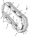
- the driven track system has a bed 1 of known form which supports an endless track 2 extending in a horizontal plane.
- the track 2 has two straight and parallel sections 3 and 4 joined by two curved end sections 5 and 6, but the track may be of any suitable configuration depending on the particular application.
- a number of carriages 10 are engaged with the track 2 in such a way as to be capable of smooth guided movement along the track.
- the underside of each carriage 10 is provided with opposing pairs of rotatable wheels 11 with V-shaped grooves engaged with V-shaped flanges 12 on opposite sides of the track 2, but again, any suitable form of engagement may be used.
- Adjacent carriages are interconnected by means of a length of belt 20 forming a flexible and non-extensible link between the adjacent carriages, such that the carriages 10 and links 20 form an endless loop.
- the lengths of belt 20 may be of the kind used in accurate timing applications, incorporating a number of longitudinally-extending metal strands encapsulated within a polymeric material.
- One face 21 of the links 20 facing towards the inside of the track 2 is smooth whilst the opposite outer face 22 is formed with alternating ribs and grooves forming a series of teeth extending transversely of the belt.
- the teeth assist in the attachment and accurate adjustment of the links 20 with respect to the carriages 10, as will be explained further below.
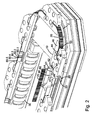
- each carriage has a pair of pick-up rollers 33, 34, which are suitably positioned and spaced such that they may both engage the screw 30 at the same time.
- the length of the screw 30 is such that the pick-up rollers of at least two adjacent carriages are always engaged with the screw to ensure that smooth continuous drive is obtained.
- the pick-up rollers 33 and 34 are mounted on an inner, downwardly inclined face 14 of the carriage, which enables the screw 30 to be positioned wholly below the top face 15 of the carriage so as not to restrict the space for mounting items on the carriage. It will however be appreciated that the number and positioning of the pick-up rollers may vary, depending on the application.
- opposite ends of the carriages 10 are provided with a pair of aligned vertical slots 44 to receive the links 20, positioned above the inner margin of the track 2.
- the ends of the carriages are provided with projecting noses 46 which provide a convex support face 47 leading from the respective slot 44 and curving inwards with a smooth profile.
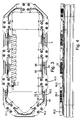
- the outside face of each slot 44 is provided with a recess 48 in which a gripper block 49 is received.
- the gripper blocks 49 can be adjusted longitudinally of the slots 44 by means of jacking screws 50, and the gripper blocks are engaged with the toothed external faces of the links 20 by means of corresponding transverse ribs and grooves.
- a compound leaf spring assembly 60 is also mounted within each slot 44 in contact with the smooth inner face 21 of the link 20.
- the leaf spring assembly may be located within the slot by means of a rolled end 61, or similar end projection, which is received in a corresponding enlargement 62 at the blind end of the slot.
- the compound leaf springs are of elongate shape, extending beyond the noses 46, and being of substantially the same transverse width as the links 20.
- Each leaf spring assembly 60 comprises a group of individual leaf springs, there being five such springs in this example.
- the spring 60.1 immediately adjacent to the link 20 is the longest of the group, having its free end 63 angled inwards away from the link to prevent wear due to contact between the end of the spring and the surface of the belt.
- the four remaining leaf springs, 60.2 to 60.5 are progressively shorter so that the stiffness of the compound spring increases from its free end towards its root. This is an important property of the spring assembly which materially assists in providing the system with the desired dynamic characteristics.
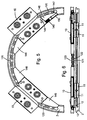
- the driven track system has an endless track 2 extending in a horizontal plane, only a curved portion of which is shown.
- a number of carriages 10 are engaged with the track 2 by means of opposing pairs of rotatable wheels 11 with V-shaped grooves, which are engaged with V-shaped flanges 12 on opposite sides of the track 2.
- the carriages are interconnected by lengths of chain 120 which are pivotally coupled to opposite ends of the carriages 10 above the track 2 such that the carriages 10 and links 120 form an endless loop.
- the chain 120 comprises spaced pairs of short rigid plates 121 which are joined by pivots 122, forming flexible and non-extensible links between the adjacent carriages.
- Other flexible but inextensible elements may be used for the connecting links such as flexible belts, metal bands, or wire ropes.
- the carriages are driven to move along the track, e.g. by a helical screw, hydraulic pushers, cam wheels or other suitable means, not shown.
- the opposite ends of the carriages 10 are provided with projecting tensioning arms 146 which each have a convex outer guide face 147 leading from the root of the link 120 adjacent to the respective carriage 10 and curving inwards with a smooth profile.
- Each of the arms is articulated to the respective carriage by a pivot 148 such that the arms can rotate inwards and outwards relative to the curvature of the track.
- One of the tensioning arms 146 has been shown cut away to reveal an internal coil spring 149, which acts between each arm 146 and the respective carriage 10 so that, on the curves, the arm is biased in an outward direction against the flexible link 120.
- the pre-compression of the springs 149 can be adjusted by means of respective pre-loading screws 150, thereby varying the outward force which the arms 146 exert on the links 120.
- the chain links 120 are substantially straight, and the arms 146 exert little or no lateral force on the chains 120.
- the leading carriage enters a curved section of the track the advancing spring-loaded arm 146 exerts an increasing outward tensioning force on the opposing portion of the chain 120 urging the adjacent end of the link towards the outer margin of the track.
- a third embodiment of the driven track system which is shown in Fig.s 7 , 8 and 9 , dynamic tensioning is achieved by oppositely-acting compression springs which allow the link attachment points to dynamically shift in a direction which is transverse to that in which the carriages travel around the track.
- the driven track system has a horizontal endless track 2 which includes the curved portion shown in Fig. 7 .
- Carriages 10 are engaged with the track 2 by means of wheels 11 with V-shaped grooves which engage V-shaped flanges on opposite sides of the track 2.
- the carriages are interconnected by lengths of chain 120 which are joined to opposite ends of the carriages 10 such that the carriages and links form an endless loop.
- the chain 120 comprises rigid plates joined by pivots to form flexible and non-extensible links between the adjacent carriages, but other forms of flexible inextensible element may be used, and in this embodiment even rigid links could be used satisfactorily.
- the carriages are driven to move along the track, e.g. by a helical screw, hydraulic pushers, cam wheels or other suitable means, not shown.
- the chain links 120 are joined to plungers 160 which are mounted at opposite ends of the carriages 10 to slide transversely of the track 2 without movement in the direction of travel around the track. As shown in the cut-away detail in Fig. 7 , the plungers 160 are biased between oppositely-acting compression springs 161 and 162 which are balanced to hold the plunger in a central position as the carriages move along straight portions of the track.
- the plungers 160 are slidably mounted within barrel housings 165 which are fixed with the opposite ends of the carriages 10.
- the barrels have openings 166 which allow the chains 120 to pass through with lateral clearance.
- the chains are inserted through holes 170 in the centre of the plunger 160 and may be secured by retaining pins 171 inserted axially through the plunger.
- the coil springs 161 and 162 are received in bores 176 and 177 in opposite ends of the plunger, acting against respective adjustable pre-loading screws 178 and 179.
- Additional means may be provided for adjusting the tension of the loop and the pitch of the carriages.
- the loop formed by the carriages 10 and links 120 is pre-tensioned so that on the curved regions of the track the link mounting points are caused to move inwards along the radius of curvature, compressing the inner spring 162 and allowing the opposing outer spring 161 to expand.
- the track can include both inward and outward curves and the tension in the loop will still be maintained.
Landscapes
- Engineering & Computer Science (AREA)
- Mechanical Engineering (AREA)
- Devices For Conveying Motion By Means Of Endless Flexible Members (AREA)
- Transmission Devices (AREA)
Applications Claiming Priority (2)
| Application Number | Priority Date | Filing Date | Title |
|---|---|---|---|
| GBGB0709483.2A GB0709483D0 (en) | 2007-05-17 | 2007-05-17 | Driven track system |
| GB0801251A GB2449325A (en) | 2007-05-17 | 2008-01-24 | Track conveyor system with tensioned flexible links |
Publications (2)
| Publication Number | Publication Date |
|---|---|
| EP1992578A2 true EP1992578A2 (de) | 2008-11-19 |
| EP1992578A3 EP1992578A3 (de) | 2009-08-12 |
Family
ID=38234610
Family Applications (1)
| Application Number | Title | Priority Date | Filing Date |
|---|---|---|---|
| EP08251669A Withdrawn EP1992578A3 (de) | 2007-05-17 | 2008-05-12 | Gesteuertes Zugsystem |
Country Status (2)
| Country | Link |
|---|---|
| EP (1) | EP1992578A3 (de) |
| GB (2) | GB0709483D0 (de) |
Cited By (3)
| Publication number | Priority date | Publication date | Assignee | Title |
|---|---|---|---|---|
| EP2460445A4 (de) * | 2009-07-31 | 2016-02-24 | Ishino Seisakusyo Co Ltd | Fördervorrichtung für speisen und getränke |
| CN109305526A (zh) * | 2017-07-27 | 2019-02-05 | 大族激光科技产业集团股份有限公司 | 一种同步轨道驱动系统、环形生产线 |
| CN113955388A (zh) * | 2021-02-03 | 2022-01-21 | 广州漂移方块智能科技有限公司 | 柔性生产线 |
Families Citing this family (2)
| Publication number | Priority date | Publication date | Assignee | Title |
|---|---|---|---|---|
| ES2395263B1 (es) * | 2011-05-12 | 2013-12-23 | Mespack, Sl | Carrusel para maquina envasadora automatica de tipo horizontal. |
| CN105151653A (zh) * | 2015-08-05 | 2015-12-16 | 滁州市昊宇滑动轴承有限公司 | 一种可自调高度的流水线式零件安装架 |
Family Cites Families (2)
| Publication number | Priority date | Publication date | Assignee | Title |
|---|---|---|---|---|
| DE2522299C3 (de) * | 1975-05-20 | 1979-10-25 | W + M Automation Karl Mueller, 6200 Wiesbaden | Transportvorrichtung zum umlaufenden horizontalen Transport von Trägern für die Förderung von Gegenständen |
| US6394260B1 (en) * | 2000-07-17 | 2002-05-28 | Pflow Industries, Inc. | Conveyor system including roller-guided carriage assemblies |
-
2007
- 2007-05-17 GB GBGB0709483.2A patent/GB0709483D0/en not_active Ceased
-
2008
- 2008-01-24 GB GB0801251A patent/GB2449325A/en not_active Withdrawn
- 2008-05-12 EP EP08251669A patent/EP1992578A3/de not_active Withdrawn
Cited By (3)
| Publication number | Priority date | Publication date | Assignee | Title |
|---|---|---|---|---|
| EP2460445A4 (de) * | 2009-07-31 | 2016-02-24 | Ishino Seisakusyo Co Ltd | Fördervorrichtung für speisen und getränke |
| CN109305526A (zh) * | 2017-07-27 | 2019-02-05 | 大族激光科技产业集团股份有限公司 | 一种同步轨道驱动系统、环形生产线 |
| CN113955388A (zh) * | 2021-02-03 | 2022-01-21 | 广州漂移方块智能科技有限公司 | 柔性生产线 |
Also Published As
| Publication number | Publication date |
|---|---|
| GB0709483D0 (en) | 2007-06-27 |
| GB0801251D0 (en) | 2008-02-27 |
| EP1992578A3 (de) | 2009-08-12 |
| GB2449325A (en) | 2008-11-19 |
Similar Documents
| Publication | Publication Date | Title |
|---|---|---|
| EP1992578A2 (de) | Gesteuertes Zugsystem | |
| EP1726848A2 (de) | Spanner zum simultanen Spannen mehrerer Stränge | |
| EP2496861B1 (de) | Mehrsträngige spannungsanordnung mit beweglichen armen | |
| EP0824489B1 (de) | Angetriebene Umlenkung für ein Transportband | |
| KR101791400B1 (ko) | 연속 벨트 또는 체인 구동 시스템을 위한 인장 기구 | |
| US8272503B2 (en) | Support device for a conveyor installation and method for operation of a conveyor installation | |
| EP2572120B1 (de) | Mechanischer spanner mit einweg-dämpfung | |
| EP1982093B1 (de) | Blattspanner mit entgegengesetzten spannen | |
| CN103836134B (zh) | 链张紧装置 | |
| EP2427396A1 (de) | Einrastbare trageführung | |
| EP1054825A1 (de) | Fördervorrichtung | |
| US6334528B1 (en) | Variable-width spacer | |
| US5992615A (en) | Curved conveyor section | |
| EP1258656B1 (de) | Spannvorrichtung mit Blattfeder und Kettenanordnung | |
| US7632200B2 (en) | Common link dual arm tensioning device | |
| JPH04211750A (ja) | チエーンベルト | |
| CA2062532C (en) | Chain belt | |
| US9162829B2 (en) | Conveyor | |
| CN1616190A (zh) | 机加工板件用的工作站 | |
| US6357580B1 (en) | Belt-type carrier system | |
| DE3908836A1 (de) | Kettenband fuer v-foermige kettenrollen | |
| CN212952596U (zh) | 一种物品输送机构及分拣机 | |
| CN103648929A (zh) | 用于物品分类装置的操作单元 | |
| EP1867893A2 (de) | Kraftübertragungskette und Kraftübertragungsvorrichtung damit | |
| JP7442440B2 (ja) | チェーン駆動ジョーシステム用の張力調整装置 |
Legal Events
| Date | Code | Title | Description |
|---|---|---|---|
| PUAI | Public reference made under article 153(3) epc to a published international application that has entered the european phase |
Free format text: ORIGINAL CODE: 0009012 |
|
| AK | Designated contracting states |
Kind code of ref document: A2 Designated state(s): AT BE BG CH CY CZ DE DK EE ES FI FR GB GR HR HU IE IS IT LI LT LU LV MC MT NL NO PL PT RO SE SI SK TR |
|
| AX | Request for extension of the european patent |
Extension state: AL BA MK RS |
|
| PUAL | Search report despatched |
Free format text: ORIGINAL CODE: 0009013 |
|
| AK | Designated contracting states |
Kind code of ref document: A3 Designated state(s): AT BE BG CH CY CZ DE DK EE ES FI FR GB GR HR HU IE IS IT LI LT LU LV MC MT NL NO PL PT RO SE SI SK TR |
|
| AX | Request for extension of the european patent |
Extension state: AL BA MK RS |
|
| AKX | Designation fees paid | ||
| REG | Reference to a national code |
Ref country code: DE Ref legal event code: 8566 |
|
| STAA | Information on the status of an ep patent application or granted ep patent |
Free format text: STATUS: THE APPLICATION IS DEEMED TO BE WITHDRAWN |
|
| 18D | Application deemed to be withdrawn |
Effective date: 20100213 |