EP1992583A2 - Commande de grue, grue et procédé - Google Patents
Commande de grue, grue et procédé Download PDFInfo
- Publication number
- EP1992583A2 EP1992583A2 EP08008276A EP08008276A EP1992583A2 EP 1992583 A2 EP1992583 A2 EP 1992583A2 EP 08008276 A EP08008276 A EP 08008276A EP 08008276 A EP08008276 A EP 08008276A EP 1992583 A2 EP1992583 A2 EP 1992583A2
- Authority
- EP
- European Patent Office
- Prior art keywords
- crane
- load
- cable
- rope
- control according
- Prior art date
- Legal status (The legal status is an assumption and is not a legal conclusion. Google has not performed a legal analysis and makes no representation as to the accuracy of the status listed.)
- Granted
Links
Images


Classifications
-
- B—PERFORMING OPERATIONS; TRANSPORTING
- B66—HOISTING; LIFTING; HAULING
- B66C—CRANES; LOAD-ENGAGING ELEMENTS OR DEVICES FOR CRANES, CAPSTANS, WINCHES, OR TACKLES
- B66C13/00—Other constructional features or details
- B66C13/18—Control systems or devices
- B66C13/46—Position indicators for suspended loads or for crane elements
-
- B—PERFORMING OPERATIONS; TRANSPORTING
- B66—HOISTING; LIFTING; HAULING
- B66C—CRANES; LOAD-ENGAGING ELEMENTS OR DEVICES FOR CRANES, CAPSTANS, WINCHES, OR TACKLES
- B66C13/00—Other constructional features or details
- B66C13/04—Auxiliary devices for controlling movements of suspended loads, or preventing cable slack
- B66C13/06—Auxiliary devices for controlling movements of suspended loads, or preventing cable slack for minimising or preventing longitudinal or transverse swinging of loads
- B66C13/063—Auxiliary devices for controlling movements of suspended loads, or preventing cable slack for minimising or preventing longitudinal or transverse swinging of loads electrical
-
- B—PERFORMING OPERATIONS; TRANSPORTING
- B66—HOISTING; LIFTING; HAULING
- B66C—CRANES; LOAD-ENGAGING ELEMENTS OR DEVICES FOR CRANES, CAPSTANS, WINCHES, OR TACKLES
- B66C13/00—Other constructional features or details
- B66C13/04—Auxiliary devices for controlling movements of suspended loads, or preventing cable slack
- B66C13/08—Auxiliary devices for controlling movements of suspended loads, or preventing cable slack for depositing loads in desired attitudes or positions
- B66C13/085—Auxiliary devices for controlling movements of suspended loads, or preventing cable slack for depositing loads in desired attitudes or positions electrical
Definitions
- the present invention relates to a crane control of a crane having at least one cable for lifting a load. Furthermore, in a further embodiment, the present invention relates to the crane control of a crane, which has at least a first and a second cable strand for lifting a load.
- the crane control controls the interlocking systems of the crane.
- the crane is a jib crane which has a boom which is pivotable about a horizontal axis and which is articulated on a tower rotatable about a vertical axis.
- a luffing mechanism and a slewing are provided as interlockings.
- the rope for lifting the load thereby runs over the tip of the jib, in particular via one or more deflection rollers arranged there, so that the load can be moved in the radial direction by rotating the tower in the tangential direction and by rocking the jib.
- a first and a second strand of rope run both strands of cable from the tip of the boom to a receiving element such as a hoes.
- the length of the rope is adjustable by a corresponding drive to move the load in the vertical direction.
- the crane control according to the invention generally relates to rotary cranes, as well as mobile harbor cranes, ship cranes, off-shore cranes, mobile cranes and crawler cranes.
- gyroscope units are used to determine the load oscillation, which are arranged in the crane hook and determine the angular speed of the cable.
- the rope angle is determined via an observer circuit, which integrates the movement of the rope.
- a freely oscillating pendulum whose rest position corresponds to a vertical rope angle.
- the crane operator must therefore continue to align the crane by hand and in sight before the stroke or at the beginning of the stroke so that the rope is aligned substantially vertically.
- this is often extremely difficult, so that deviations of the rope angle from the vertical result, which lead to unwanted vibrations when lifting the load.
- the same problem arises when, due to an imbalance of the load, the rope is vertically aligned before the stroke, but the rope angle is changed when lifting the load by the movement of the center of gravity of the load below the load receiving point.
- the yielding of the crane structure under the load when lifting the load can change the rope angle unintentionally.
- the additional problem arises that the rope angle can be changed by a relative movement of a ship carrying the load to the offshore crane.
- Object of the present invention is therefore to provide a crane control available through which enables easier and safe alignment of the crane, especially before and during the lifting of the load. It is another object of the present invention to provide an improved damping of the spherical pendulum vibrations of the load.
- this object is achieved by a crane control according to claim 1.
- This has according to the invention a sensor unit for determining a Rope angle relative to the direction of gravity force.
- the cable angle can be determined directly relative to the direction of gravitational force, so that the vertical alignment of the cable is considerably simplified. This also increases the security of the hub.
- the sensor unit usually have an element which aligns under the influence of the gravitational force and by which the angle of the rope relative to the direction of gravitational force can be determined.
- any type of electric dragonfly can be used.
- the sensor unit can only determine whether the rope is vertically aligned or not.
- the direction of the deviation from the vertical and in further embodiments the value of the deviation from the vertical can also be determined.
- the cable unit can determine the cable angle in at least one direction relative to the direction of gravity, for example by the sensor unit. in the radial or in the tangential direction, in order to be able to determine a deviation of the rope angle from the perpendicular in this direction and to be able to compensate if necessary.
- the cable angle is determined both in the tangential and in the radial direction, since only in this way is an actual vertical alignment of the cable possible.
- the sensor unit advantageously has at least two sensors which each serve to determine the radial or the tangential cable angle relative to the direction of gravitational force.
- the sensor unit By such a sensor unit, a precise alignment of the crane when lifting the load is possible, so that the rope is aligned vertically. Similarly, the sensor unit can be used for monitoring and security functions.
- At least one gyroscope unit for measuring a cable angular velocity is furthermore provided.
- this gyroscope unit can continue to be used for vibration damping oscillating load are used, for which the sensor unit for determining the rope angle relative to the gravitational force direction usually can not provide sufficiently accurate data.
- the orientation of the crane can then be carried out first based on the sensor unit for determining the cable angle relative to the direction of gravity force until the load hangs freely on the rope. Thereupon, the automatic cable oscillation damping, which operates on the basis of the gyroscope unit, can be switched on.
- the gyroscope unit measures the cable angular velocity in at least one direction, e.g. in the radial or in the tangential direction.
- both the tangential and the radial cable angular velocity are determined, for which purpose the gyroscope unit advantageously has at least two appropriately arranged gyroscopes.
- the crane control advantageously comprises at least two sensor units for determining the cable angles relative to the direction of gravitational force, which are assigned to different cable strands.
- a cable field rotation which corresponds to a rotation of the load, are taken into account. If only one sensor unit were used here with several cable strands, however, a cable field rotation would lead to corrupted measured values.
- the cable field rotation and thus the rotation of the load, can be determined by the at least two sensor units. This makes it possible, before the start of the stroke and the cable field twist z. B. offset by a rotation of the lifting device relative to the load.
- the crane has at least two cable strands for lifting the load, advantageously at least two gyroscope units are also provided for measuring the cable angular velocities, which are assigned to different cable strands. So the rope field twist z. B. also be taken into account in the vibration damping drive.
- the sensor unit and / or the gyroscope unit are arranged on a cable follower element, which is connected in particular via a gimbal connection with a jib of the crane and which is guided on the cable.
- the cable follower element is preferably connected by the gimbal connection with the boom head of the crane and follows the movements of the rope on which it is guided by rollers. By measuring the movement of the cable follower element so the movements of the rope can be determined.
- the crane has at least two cable strands for lifting the load, advantageously at least two cable follower elements are provided, which are assigned to different cable strands. Since the hook of the crane usually depends on several cable strands, so also rope field distortions can be considered.
- the crane control according to the invention comprises a display unit for displaying a deviation resulting from the measured cable angle, in particular for displaying a cable angle relative to the direction of gravitational force and / or a resulting horizontal deviation of the load.
- This display considerably facilitates the crane operator's alignment of the rope in a vertical position.
- the display shows a vertical cable position optically and / or acoustically. This makes it possible for the crane operator to align the rope accordingly.
- the display further indicates the direction in which the rope deviates from the perpendicular. Further advantageously, the display also indicates the absolute value of the deviation. It is conceivable z. Example, a graphical display in which the angle of the rope relative to the direction of gravitational force and further advantageously displayed the maximum permissible rope angle become. Alternatively or additionally, the horizontal deviation of the load from the position at which the load would be located in the vertical cable position can be displayed, advantageously together with the maximum permissible horizontal deviation. This allows the crane operator to work with well-known distance indications and to align the crane more easily.
- a warning device which warns the crane operator when exceeding an allowable value range for a resulting from the measured rope angle deviation, in particular for the rope angle relative to the gravitational force direction and / or for the horizontal deviation of the load, in particular by an optical and / or acoustic signal.
- the crane operator can react when exceeding the permissible value range and avoid damage to the crane structure or accidents.
- the crane operator can stop the movement of the crane when exceeding the permissible angle range, or, if it is an off-shore crane, in which the z. B. load on a ship is moved away by a relative movement of the ship relative to the crane from the off-shore crane, avoid by a partial release of the rope or the slewing gear of the crane overload.
- a safety device in particular an overload protection device, which automatically exceeds a permissible value range for a deviation resulting from the measured cable angle, in particular for the cable angle relative to the gravitational force direction and / or for the horizontal deviation of the load engages the crane, in particular to prevent overload of the crane.
- the rope angle relative to the gravitational force direction can thus be included in the automatic load moment limitation of the crane. This considerably increases the safety of the operation, since known load torque limitations could not take this parameter into account and the loads resulting from an excessive inclination of the cable had to be taken into account solely via the other transducers.
- the overload protection stops the movement of the crane automatically. This prevents overloading of the crane structure due to excessive skewing of the cable. Likewise, accidents can be avoided by the safety device in addition to the overload of the crane, e.g. if, when the permissible value range is exceeded, lifting of the load is automatically prevented in order to avoid excessive swinging when the load comes free.
- the crane has at least two cable strands for lifting the load, its cable field rotation is advantageously determined. Since in a pure rotation of the load, the outer cables are deflected in opposite directions, respectively, without the load would be deflected from the vertical, this Seilfeldvermosung advantageously taken into account in the determination of the actual cable angle.
- the rope angle which is used in the display, the warning device and / or the overload protection, thereby corresponds to the actual deflection of the load relative to the gravitational force direction, so that oscillation of the load can be effectively prevented and any Seilfeldverrectoder not lead to incorrect values.
- a safety device in particular an anti-rotation, provided which automatically engages in an excess of an allowable value range for the Seilfeldvermosung in the control of the crane. For example, a lifting of the load can be automatically prevented in case of excessive rotation of the rope field.
- the crane control according to the invention has an automatic load oscillation damping.
- the movement of the crane can be controlled so that during a movement of the crane, a swinging of the free-swinging load is prevented.
- the sensor unit for determining the cable angle relative to the direction of gravitational force can thereby at the beginning of the stroke be used for vertical alignment of the rope, while the load swing damping starts when the load is hanging freely on the rope.
- the correct orientation of the rope can prevent the load from swinging during lifting, while the load swing damping prevents the load from oscillating as it moves in the horizontal direction.
- the load oscillation damping is based on the data of at least one gyroscope unit. Since the cable angular velocity can be determined with a gyroscope, it is particularly well suited for use in load swing damping.
- the sensor unit is used for determining the cable angle relative to the direction of gravitational force for monitoring and / or calibration of the gyroscope unit.
- the load-swing damping which usually starts from a free-running load, would otherwise start with incorrect values.
- the sensor units or gyroscope units can also be used for mutual monitoring in order to detect malfunctions.
- a function for automatic alignment of the crane is further provided by which the rope is aligned perpendicular to the load.
- the crane operator no longer has to do this manually with the crane. B. based on the display, but this is done automatically with a corresponding request from the crane operator via an operating unit.
- a security function is provided which z. B. cooperates with a rope force sensor to prevent in case of malfunction of the sensor unit for determining the rope angle relative to the direction of gravity force an uncontrolled movement of the crane.
- a function for automatic alignment of the crane is provided, compensated by which a rope field twist becomes.
- This advantageously controls a rotor unit on the load receiving device, for example on the spreader, through which the connected to the ropes part of the load bearing device can be rotated relative to the load.
- the crane control according to the invention has a memory for storing load data on the basis of the rope angle, which the life calculation and / or documentation z. B. of improper use.
- Such a machine data acquisition of the cable position for load spectrum determination and documentation thus enables a more accurate life cycle calculation and thus increased safety at saved costs.
- the alignment of the crane before and when lifting the load is considerably simplified.
- the cable field rotation is determined when several cable strands are used to lift the load.
- the cable angles of at least two cable strands are determined relative to the direction of gravitational force. From this data can then be determined both the cable angle, which the deflection of the load, as well as the cable field rotation, which corresponds to the rotation of the load.
- the rope is brought into a vertical orientation before lifting the load.
- This can be prevented by an inclination of the rope when lifting the load this slips laterally, uncontrolled twisted by uneven resting on the surface or already performs a pendulum movement when lifting.
- the vertical orientation of the load can be z. B. by the crane operator based on the display of the cable angle according to the invention relative to the direction of gravitational force. It is also conceivable that this alignment is carried out automatically by the crane control as already described.
- the cable field twist is brought to zero to avoid rotation of the load during lifting. This is done z. B. by corresponding rotation of the load on the load receiving means by means of a rotor assembly.
- a deviation of the cable angle is compensated by the vertical even during the lifting of the load.
- this is determined during the lifting of the load of the rope angle relative to the direction of gravity force, so that any deviations occurring during the lifting process can be compensated.
- an imbalance of the load is determined when lifting the load by determining the occurring deviation of a rope angle of the vertical. If the load is unbalanced, ie if the center of gravity of the load is not below the load pick-up point, the load pick-up point initially moves above the center of gravity when lifting the load so that the rope angle changes. This change in the rope angle, the imbalance of the load can be determined and possibly compensated. Such an imbalance of the load can also be displayed, so that it can be compensated by the crane operator. It is also conceivable to automatically compensate for such an imbalance.
- the imbalance of the load is thereby compensated on the basis of the deviation of a cable angle from the vertical by a movement of the load on the load receiving means, in particular on the spreader.
- the spreader serves to receive containers and has a longitudinal adjustment, by which the load receiving point can be adjusted relative to the container.
- the crane operator can now z. B. based on the deviation of the rope angle of the perpendicular, which is formed when lifting the load by the imbalance and is displayed on the display according to the invention, move the load receiving point on the load receiving means and so compensate for the imbalance.
- the imbalance of the load is determined and displayed, this facilitates the work of the crane operator. It is also conceivable that an automatic compensation of the imbalance takes place.
- the inclination of the rope caused by the imbalance of the load when lifting the load can also be compensated by movement of the crane. This can either manually via the crane operator z. B. based on a display or automatically.
- the crane structure is protected by countermeasures.
- the movement of the crane can be stopped in order to avoid overload.
- the countermeasures advantageously comprise at least partial release of the crane movements and / or of the rope in order, for. B. in a hooking of the lifting device with a ship, which moves away from the off-shore crane, to prevent overloading of the crane.
- the countermeasures can either be initiated by the crane operator, which is advantageously warned by a warning function, or automatically by a corresponding automatic overload protection.
- the present invention comprises a crane, in particular a mobile harbor crane, a ship crane or an off-shore crane, which has a cable for lifting a load and is equipped with a crane control as described above.
- the invention comprises corresponding boom and / or slewing cranes, as well as mobile cranes and crawler cranes. Obviously arise for such a crane the same, already described in the crane control advantages.
- the crane control serves to control the interlockings of a crane, which has at least a first and a second cable strand for lifting a load, wherein the crane control has a load oscillation damping for damping spherical pendulum vibrations of the load.
- a first and a second sensor unit are now provided, which are assigned to the first and the second cable strand, in order to determine the respective cable angles and / or cable angular velocities of the first and second cable strands.
- the load oscillation damping has a control into which the cable angles and / or cable angular velocities determined by the first and the second sensor unit are received.
- the controlled by the crane control signal boxes are advantageously the slewing gear for rotating the crane and / or the luffing mechanism for luffing the boom.
- the first and the second sensor unit each comprise a gyroscope unit.
- the gyroscopes measure the rope angular velocity, advantageously two gyroscopes are provided to measure the rope angular velocity in both the radial and tangential directions. Gyroscopes are particularly well suited for the requirements of the control of the load oscillation damping.
- the first and second sensor units of the present invention are each arranged in a cable follower element.
- the cable follower element follows the movement of that cable strand to which it is assigned.
- the sensor unit in turn measures the movement of the cable follower element, from which the movement of the cable strand can be determined.
- the cable follower elements are each connected via a gimbal joint with the boom of the crane and follow the movement of the rope strand, which they are assigned.
- the connection of the cable follower elements via a gimbal joint advantageously serves only the mechanical connection and the guidance of the cable follower element, while the sensor units determine the movement of the cable follower elements via the gyroscope units according to the invention.
- a compensation of the data measured by the first and the second sensor unit takes place with respect to the installation angle of the sensor units and the angle of rotation of the crane.
- interference which are caused by incorrect installation, be compensated software technology.
- the sensors proportionally measure the rotational speed of the crane. This is taken into account by the compensation according to the invention.
- sensor errors are detected in the crane control according to the invention by comparing the data measured by the first and the second sensor unit. If one of the sensor units fails, the angular velocity is still detected by the other sensor unit. Thus, the basic function of the crane control can continue to be ensured. By subtraction of the angle signals of both sensor units in the respective directions can continue to detect a sensor error when a threshold value is exceeded. The crane can be brought to a safe condition immediately when a sensor fault occurs.
- control of the crane control according to the invention is non-linear.
- a non-linear control is of particular advantage, since in particular for jib cranes, the entire system of crane, interlockings such. As hydraulic cylinders and load is non-linear and thus considerable errors occur in a purely linear control.
- the entire control path of non-linear control and the non-linear behavior of the crane, in turn, according to the invention in turn results in a linear path, so that the control of the system is considerably simplified.
- control is based on the inversion of a physical model of the movement of the load as a function of the movements of the interlockings.
- this physical model is a nonlinear model, so that its inversion results in the inventive non-linear control.
- Input variables of the physical model are the state vector of the crane. Based on these inputs, the non-linear model then indicates the movement of the load as the output.
- the load-deflection device has a path planning module which predetermines the regulation of target trajectories. These desired trajectories specify the movements which the load is to carry out and are then used, in particular, when using an inverted model as as input variables of the control.
- the non-linear control results in a particularly simple implementation of the path planning module, since this only has to specify desired trajectories for the linear system of non-linear control and non-linear crane behavior. This makes it possible to achieve an extremely fast crane control with an outstanding response to the specifications entered by the crane operator by means of input elements.
- the current system state of the crane enters the path planning module as an input variable.
- the position of the cantilever is important because z. B. depends on the maximum achievable radial velocity of this.
- the cable angles and / or cable angular velocities determined by the first and second sensor units also enter from input variables into the path planning module. This additional control loop thus enables a more accurate path planning taking into account the actual cable angle and / or the actual cable angular velocity.
- restrictions of the system in the generation of the desired trajectories are taken into account. This prevents that calculated from the specifications of the crane operator guide variables, the manipulated variable limitations of the system such. B. violate the maximum speed.
- restrictions of the system that depend on this system state can also be taken into account. For example, the maximum possible radial speed depends on the position of the cantilever.
- the trajectory generation according to the invention is based on optimal control. According to the invention, such optimal control can be implemented particularly well in real time, since the nonlinear system according to the invention Regulation allows a particularly simple implementation of the path planning module.
- the path planning module according to the invention operates in the prediction within the time horizon with an increasing length of the calculation intervals.
- the position and the speed of the boom head is also involved in the regulation of the load oscillation damping. This results in the crane control according to the invention control loops both for the position and the speed of the boom head, as well as for the rope angle and / or rope angular velocity of the rope.
- the second embodiment of the present invention with the use of two sensor units, which are each assigned to different cable strands of the crane, has hitherto been described independently of the first embodiment with a sensor unit for determining a cable angle relative to the direction of gravitational force. According to the invention, protection is claimed independently for both embodiments.
- both embodiments of the present invention are combined.
- the system according to the invention with two sensor units in this case has one or more of the features which have been previously described with respect to the embodiment of the invention with a sensor unit for determining a cable angle relative to the direction of gravity force.
- the present invention further comprises a crane for lifting a load, with interlocking mechanisms for moving the crane and the load and with a crane control for controlling the interlockings, wherein the crane control has a load sway loss for damping spherical pendulum vibrations of the load and wherein the crane at least two cable strands for lifting the load.
- the crane control has a load sway loss for damping spherical pendulum vibrations of the load and wherein the crane at least two cable strands for lifting the load.
- two sensor units which are assigned to the two cable strands, are provided in order to determine the respective cable angles and / or cable angular velocities.
- the load oscillation damping in this case has a control, in which enter the determined by the two sensor units rope angle and / or rope angular velocities.
- the crane according to the invention has a crane control, as described above.
- the crane according to the invention as interlockings while a slewing gear for rotating the crane and / or a luffing mechanism for luffing a boom, which are controlled by the crane control.
- a slewing gear for rotating the crane and / or a luffing mechanism for luffing a boom which are controlled by the crane control.
- the present invention further comprises a method for driving the interlocking of a crane, which has at least a first and a second cable string for lifting the load, wherein spherical pendulum vibrations of the load are damped by a load oscillation damping.
- a compensation of the data measured by the first and the second sensor unit with respect to the installation angle of the sensor units and the rotation angle of the crane can be compensated by an exact radial or tangential alignment.
- sensor errors are detected by comparing the data measured by the first and second sensor units. It can be exploited by the inventive use of two sensor units, which are assigned to the respective cable strands, the redundancy gained thereby.
- the torsional vibration of the cable field is taken into account in the load oscillation damping by an averaging of the cable angles determined by the first and second sensor units and / or cable angular velocities. So load swing damping can be taken into account that also torsional vibrations of the rope field occur, which influence the data of the sensor units.
- the method according to the invention is carried out with a crane control, as described above.
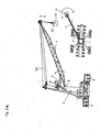
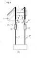
- FIG. 0a an embodiment of a jib crane according to the invention is shown, here a mobile harbor crane, as they are often used for handling cargo handling operations in ports.
- Such boom cranes can have load capacities of up to 140 t and a rope length of up to 80 m.
- the embodiment of the crane according to the invention in this case comprises a boom 1, which can be pivoted about a horizontal axis 2, with which it is hinged to the tower 3, up and down.
- the tower 3 can in turn be rotated about a vertical axis, whereby the boom 1 is rotated.
- the tower 3 is rotatably arranged for this purpose on an undercarriage 6, which is movable via wheels 7.
- interlockings are present, for rocking the boom 1, the actuator 4.
- the rope 20 for lifting the load 10 is guided over a pulley on the boom head, wherein the Length of the rope 20 can be adjusted via winches.
- a load receiving device is arranged at a load receiving point 25, for.
- the load receiving device additionally has a rotator device, via which the load 10 can be rotated on the load receiving device.
- the crane further comprises at least a first and a second cable strand for lifting the load, wherein all cable strands run from the jib tip to the load receiving device.
- the load can be moved by rotating the tower 3 in the tangential direction and by rocking the boom 1 in the radial direction. In the vertical direction you load 10 is thereby moved by the luffing of the boom 1 and the change in the length of the cable 20.
- the load 10 can be rotated by the rotator unit on the load receiving device.
- a first embodiment of the in Figure 0a shown mobile crane is now equipped with the crane control according to the invention, which has a sensor unit for determining the cable angle relative to the direction of gravity force.
- the sensor unit has two sensors, by means of which in each case the radial or the tangential cable angle relative to the direction of gravitational force can be determined.
- the crane control according to the invention can be used not only in the illustrated embodiment, ie a mobile harbor crane, but also advantageously in other cranes, such as. As in ship cranes, off-shore cranes, truck cranes and crawler cranes.
- the sensor unit according to the invention for determining the cable angle relative to the direction of gravitational force is particularly advantageous in the case of jib cranes, since in these known systems, as described, for example, in US Pat. B. in cranes with a movable only in the horizontal direction trolley are used and which work on Meßmicrosysteme not be used.
- such measuring camera systems would in fact move together with the jib and thus only determine the angle of the rope with respect to the jib, but not with respect to the vertical.
- such systems would always have to be located directly behind the cable fix point on the boom head, which is hardly possible with a guided over a pulley on the boom head movable rope.
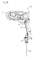
- the sensor unit according to the invention for determining the cable angle relative to the direction of gravitational force can be used without problems in a cable follower element 35, as is shown in FIG FIG. 0b is shown, and directly determines the rope angle relative to the gravitational force direction in the tangential and radial directions.
- the rope angle relative to the boom 1 can be completely dispensed with.
- this angle of the rope relative to the boom 1 of interest could also be arranged on the boom 1 another sensor unit for determining the angle of the boom relative to the gravitational force direction to the difference between the respective angle of rope and boom to the gravitational force direction, the angle between rope and to determine boom.
- FIG. 0b shown rope follower element 35, on which the sensor unit is arranged for determining the cable angle relative to the direction of gravity, is attached to the boom head 30 of the boom 1 by gimbals 32 and 33 under the main pulley 31.
- the cable follower element 35 has rollers 36 through which the cable 20 is guided, so that the cable follower 35 follows the movements of the cable 20.
- the gimbals 32 and 33 allow the cable follower element to freely move about a horizontal and a vertical axis, but prevent rotational movements.
- the orientation of the cable follower element 35 and thus of the rope 20 relative to the direction of gravity force can thus be determined via the arranged on the cable follower 35 sensor unit for determining the rope angle relative to the direction of gravity force.
- corresponding cable follower elements 35 are advantageously assigned to at least two of these cable strands in order to be able to take into account the cable field twist resulting from a rotation of the load-bearing element from the cable-bed level.
- the cable follower elements are arranged on the cable strands arranged in each case outside, so that a cable field rotation is expressed maximally in the difference between the cable angles.
- the actual cable angle relative to the gravitational force direction which corresponds to a deflection of the load from the vertical, can be determined by averaging the values from the sensor units at the respective cable follower elements, the rotation of the load from the difference of the values.
- the universal joint 32 and 33 serves only the mechanical connection of the cable follower element 35 with the boom head 30, the measurement of the cable angle takes place solely via the sensor units integrated in the cable follower elements 35, but not by determining the angle between the cable follower element 35 and the boom 30. As a result, only the relative orientation of the rope with respect to the boom 30 could be determined, but not the rope angle of the rope 20 relative to the direction of gravity force.
- first and a second strand of rope are provided, via which the load-receiving element is suspended on the boom, these are also associated with corresponding cable follower elements 35, which are equipped with gyroscope units and thus determine the rope speed of these cable strands.
- the determination of the cable speeds of the first and the second cable strand makes it possible to take into account the cable field distortion in the load swing damping for damping spherical pendulum oscillations of the load and to correct measuring errors.
- the sensor units for determining the cable angle relative to the direction of gravitational force can also be dispensed with and the cable follower elements 35 can only be equipped with gyroscope units.
- the crane control according to the invention is now provided with the sensor unit according to the invention for determining a rope angle relative to the direction of gravity force.
- FIG. 1a shows the basic problem with a non-perpendicular orientation of the rope 20.
- FIGS. 1a and 1b is exemplified the deflection ⁇ Sr shown in the radial direction.
- the same problem also arises for a deflection of the rope 20 in the tangential direction, which is caused by a faulty position of the tower 3.
- the embodiment of the crane control according to the invention therefore has a display which indicates the rope angle ⁇ of the rope 20 relative to the gravitational force direction, that is to the vertical.
- the display can be z. B. on the one hand a vertical rope position optically and / or acoustically indicate and also indicate the direction in which the cable 20 is deflected by the perpendicular.
- Such a display can thus z.
- the horizontal deviation of the load from a zero position which corresponds to a vertical orientation of the rope, can be displayed.
- a graphical display of the zero position and the deviation of the load is conceivable, so that the crane operator, the absolute deflection of the load is displayed directly.
- the crane operator can easily align the crane at the beginning of the stroke so that the cable 20 is arranged vertically above the load 10.
- the correct vertical rope position can then z. B. be acoustically displayed by a beep.
- a function for automatic alignment of the rope in the vertical direction is provided, optionally in addition to the display.
- the crane automatically aligns with the load after attaching the load handler so that the rope is in the vertical position.
- this automatic function is advantageously z. B. connected to a Seilkraftmeß worn, which switches off the automatic operation in case of errors.
- the embodiment of the crane control according to the invention in addition to the display on a warning device which the crane operator when exceeding permissible value range for a resulting from the measured rope angle deviation, in particular for the rope angle relative to the direction of gravitational force, for the horizontal deviation of the load and / or the rope field rotation by an optical and / or acoustic signal warns.
- the crane operator has the ability to prevent excessive deflection of the rope and so the crane z. B. to protect against overload. Likewise, too much oscillation of the load when lifting can be avoided.
- an automatic security device e.g. be provided in the form of an overload protection, which automatically engages in the control of the crane when the permissible value range is exceeded.
- the automatic overload protection stops the movement of the crane in order to prevent overloading.
- the overload protection can be integrated into the load torque limit of the crane, which protects the crane against loading by a too large rope angle.
- the deviation of the rope angle is determined by the vertical.
- the crane operator checks on the display the rope angle or the horizontal deviation and adjusts the crane during the stroke to compensate for the deviation of the rope angle from the vertical by the imbalance of the load again.
- the imbalance of the load from the deviation of the rope angle from the vertical is determined and displayed, so that the crane operator can respond better.
- the load-receiving means comprises a device for the particular linear movement of the load 10 relative to the load receiving point 25, via which the center of gravity 26 of the load can be arranged without tilting the load 10 below the load receiving point 25.
- the load handling device z. B. a spreader, z. B. a longitudinal displacement of the load receiving point 25 relative to the load, for.
- the crane operator can move the load-bearing point relative to the load until the cable is again aligned vertically.
- the imbalance of the load can be determined and displayed, so that the crane driver controlling the Longitudinal adjustment of the spreader can make use of this display.
- an automatic adjustment of the spreader is conceivable.
- Such an adjustment of the spreader on the basis of the deviation of the rope angle from the vertical is of particular advantage, since a tilting of the container, in particular when loading into a ship can lead to jamming of the container, through which the loading can be significantly impeded.
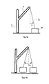
- FIGS. 3a to 3c Now, another effect can be seen, by which a deviation of the rope angle of the vertical can be caused when lifting the load.
- the rope 20 is still aligned vertically. Since the center of gravity 26 of the load is below the load receiving point 25, so the load has no imbalance, the load receiving point 25 does not move when lifting the load 10 in this case.
- the crane structure yields by the load-lifting load, in which case the tower 3 and boom 1 are slightly bent forward. As a result, the boom tip 30, over which the cable 20 runs, is moved relative to the load receiving point 25, so that there is a deviation of the cable angle from the vertical by the yielding of the crane structure.
- this deviation is compensated in a first embodiment of the method by the crane operator on the basis of the display of the rope angle when lifting the load.
- the deviation of the rope angle from the perpendicular can be determined by the yielding of the crane structure under the load, which can then be displayed to facilitate the work of the crane operator.
- an automatic tracking of the crane for vertical alignment based on the data of the sensor unit for determining a cable angle relative to the direction of gravity force is possible. If the rope angle is again aligned in the vertical direction, the load can, as in Figure 3c shown to be lifted without vibration.
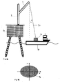
- FIG. 4a is a further embodiment of the crane according to the invention to see.
- This is an off-shore crane, which is arranged on an off-shore platform 50 and z. B. for loading a load 10 from a ship 60 on the platform 50 is used. Since the ship 60 can move relative to the platform 50, the rope angle of the rope 20 relative to the perpendicular can also be altered without movement of the crane by movement of the ship.
- an overload function is provided in one exemplary embodiment of the crane control according to the invention, which optionally can be used in addition to the warning and safety functions described above.
- countermeasures are initiated when the rope angle exceeds a maximum allowable range.
- the movement of the crane can be partially released, z. B. by the rope 20 is released or the rotational movement of the tower 3. This release is carried out in a controlled manner with a certain counterforce to avoid sudden power surges.
- an overload protection that is simple to perform can be realized, which can only be realized with difficulty by means of a cable force sensor.
- an overload protection which causes a partial release of the crane movement, also an uncontrolled grinding of the load 10 can be prevented via the ship 60.
- the permissible range 70 for the cable angle in the X and Y direction is, for example, in FIG. 4b hatched shown. If the cable angle exceeds this permissible range 70, either the warning function according to the invention or one of the overload functions according to the invention is triggered.
- FIG. 4b shows a display element for indicating a deviation from a vertical position of the rope, with an allowable range 70 for the rope angle or for the horizontal deviation in the X and Y direction, that is in the radial and tangential direction.
- the display of the rope angle is thereby graphically, for example by the rope angle in the in FIG. 4b shown diagram is shown as a dot.
- the rope angle and the horizontal deviation of the load from the zero position lying in the middle can be represented, that is, the distance of the load from the position in which it would be at the same crane position, but perpendicular rope.
- the crane driver can thus directly detect the absolute deflection of the load and thus estimate more easily how far the crane has to be moved for the correct alignment of the rope.
- the crane has at least a first and a second strand of rope, which connect the load-carrying means with the boom tip.
- an improved damping of the spherical vibrations of the load is provided by the crane control according to the invention.
- Control and automation concepts for cranes which prevent the pendulum movement of the load on the rope during a crane movement, depend on the exact measurement of the rope angles.
- the gyroscope signals are offset and also detect disturbances such as rope harmonics, observer circuits are used to integrate the velocities to the cable angles.
- the gyroscopes are attached to the rope under the cantilever tip by means of a mechanical construction. Necessary for the detection of the spherical load vibration are two gyroscopes, which are arranged in the tangential and radial directions.
- both the first and the second strand of rope a rope follower element as in Fig. 0b shown is assigned.
- the cable follower elements are equipped with gyroscope units which are better suited for load-swing damping. About this an angular velocity detection of the oscillating crane load.
- FIG. 0b shows a first cable follower element 35, on which in the embodiment shown here, the first cable strand associated with the first sensor unit is arranged.
- the first cable follower element is attached to the boom head 30 of the boom 1 by gimbal connections 32 and 33 under a first pulley 31, over which the first cable strand 20 is guided.
- the cable follower element 35 has rollers 36, through which the first cable strand 20 is guided, so that the cable follower 35 follows the movements of the cable strand 20.
- the gimbals 32 and 33 allow the cable follower element to freely move about a horizontal and a vertical axis, but prevent rotational movements.
- the radial and tangential angular velocity of the first cable follower element 35 and thus of the first cable strand 20 can thus be determined via the first sensor unit arranged on the cable follower element 35, which is designed as a gyroscope unit.
- a second cable follower element with a second sensor unit, which is assigned to a second cable strand, is constructed analogously to the first cable follower element and connected to the cantilever tip. The second cable follower element accordingly measures the angular velocity of the second cable strand.
- the gyroscope signals (angular velocities in the tangential and radial directions) of both cable follower elements are processed and processed using identical algorithms. First of all, interference caused by incorrect installation is compensated by software (see equation 0.1). If the sensitivity levels of the gyroscope sensors are not tilted exactly in the tangential and radial directions, but tilted by incorrect assembly, the sensors measure the rotational speed of the crane proportionally.
- ⁇ ⁇ t / R comp ⁇ ⁇ t / Rmeas - sin ⁇ installation ⁇ ⁇ ⁇ D
- the mounting or mounting angle for each gyroscopic sensor on both cable follower elements is ⁇ installed , ⁇ D is the crane's rotational speed, ⁇ t / rmess is the tangential or radial angular velocity, and ⁇ t / rkomp is the resulting compensated gyroscope signal .
- the compensated measuring signals are integrated offset-free to the cable angles with an observer circuit.
- the rope angles are now available for both cable follower elements in tangential and radial directions.
- the first advantage is the redundancy of the load swing measurement. If a sensor fails on one of the two cable follower elements, the angular velocity is still detected by the sensor of the other mount. Thus, the basic function of the crane control (the pendulum damping and Trajektorien laminate) can be ensured. By subtraction of the angular signals of both cable follower elements in the respective directions can continue when a threshold value is exceeded detect a sensor error. Thus, the crane can be immediately brought to a safe condition when a sensor error occurs.
- the second advantage is the possibility of compensating the torsional vibration of the load.
- Equation 0.2 the mean value of the angle signals of the two cable follower elements in the corresponding direction is calculated.
- ⁇ t ⁇ tbeobH ⁇ 1 + ⁇ tbeobH ⁇ 2 2
- ⁇ r ⁇ rbeobH ⁇ 1 + ⁇ rbeobH ⁇ 2 2
- the cable angle in the tangential direction ⁇ t is thus calculated from the mean value of the observed angle signals of the holder 41 ⁇ tbeobH 1 and holder 42 ⁇ tbeobH 2 .
- the gyroscopes on the cable follower elements 41 and 42 exactly measure an opposing disturbing oscillation in both the tangential and in the radial direction.
- the influence of the torsional vibration can be eliminated by averaging.
- the dynamics of boom movement is characterized by some predominant non-linear effects.
- the use of a linear controller would therefore cause large errors in trajectory tracking and inadequate damping of the load swing.
- the present invention utilizes a non-linear control approach based on the reversal of a simplified nonlinear model.
- This control procedure for the rocking movement of a jib crane allows a swing-free load movement in the radial direction.
- the resulting inventive Crane control a high accuracy Trajektoriennach entry and a good damping of load oscillation. Measurement results are presented to validate the good performance of the nonlinear trajectory tracking controller.
- Jib cranes like the LIEBHERR Mobile Harbor Crane LHM are used for the efficient handling of transshipment processes in ports.
- This type of jib crane is characterized by a load capacity of up to 140 tons, a maximum reach of 48 meters and a rope length of up to 80 meters.
- a spherical load oscillation is excited. This load oscillation must be avoided for safety and performance reasons.
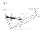
- a mobile harbor crane from a mobile platform 6, to which a tower 3 is attached.
- the tower 3 can be rotated about a vertical axis, its position being described by the angle ⁇ D.
- a boom 1 is pivotally mounted, which can be tilted by the actuator 4, wherein its position is described by the angle ⁇ A.
- the load 10 is suspended on a rope of length I S from the head of the boom 1 and can oscillate at the angle ⁇ Sr.
- the following embodiment of the present invention utilizes a flatness-based control approach for the radial direction of a boom crane.
- the approach is based on a simplified nonlinear model of the crane.
- the law of linearizing control can be formulated.
- the zero dynamics of the non-simplified non-linear control loop guarantees a sufficient damping characteristic.
- Fig. 8 shows a schematic representation of the rocking motion, where ⁇ Sr, the radial rope angle, ⁇ Sr, the radial angular acceleration, l s is the cable length, r ⁇ A is the acceleration of the boom end and g is the gravitational constant.
- the second part of the dynamic model describes the kinematics and dynamics of the actuator for the radial direction.
- T W is the time constant
- a zyl is the cross-sectional area of the cylinder
- u W is the input voltage of the servo valve
- K VW is the proportional constant of flow rate to u w .
- Fig. 9 shows a schematic representation of the kinematics of the actuator with the geometric constants d a , d b , ⁇ 1 , ⁇ 2 .
- FIG. 10 shows the resulting structure of the linearized and stabilized system.
- the problem of trajectory generation is formulated as a limited open-chain optimal control problem for the linearized state feedback system. Due to the relevant calculation time for the solution of the optimal control problem, the model predictive trajectory generation is performed with a non-negligible sampling time. Also, a discretization of the time axis is introduced by the numerical solution method itself. For the sake of simplicity, however, the optimal control problem is continuously represented in continuous time.
- the state variables x lin are the states of the integrator chain resulting from the linearized system consisting of flatness-based controller (equation (14)) and nonlinear system (equation (6)) and the states of the integrator chain for the reference trajectory. Additional states are introduced to get a smooth input ⁇ .
- the initial state x lin , 0 is derived from the states of these integrators, the current system output and its derivatives.
- the outputs y lin of the linear system (Equation (15)) are variables corresponding to the shallow output y * (Equation (12)) and its first and second derivatives. These variables are the position, velocity and acceleration of the load in the radial direction.
- the quality functional J c 1 2 ⁇ t 0 t f y lin - w T ⁇ Q ⁇ y lin - w + r ⁇ u ⁇ lin 2 ⁇ dt considers on the one hand the quadratic deviation of the predicted outputs y lin from their reference prediction w ( t ) and on the other hand the quadratic change of the input quantity u lin .
- the optimization horizon t f -t 0 , the symmetric, positive semi-definite weighting matrix Q and the weighting coefficient r > 0 are essential setting parameters for the model predictive trajectory generation.
- the optimization horizon t f - t 0 should capture the essential dynamic behavior of the process / system. This is defined by the period of the load donation (up to 18 seconds for the considered crane). Experiments show that 10 seconds are sufficient for the optimization horizon.
- the reference prognosis w ( t ) for the load position, speed and acceleration is generated from the hand lever signals of the crane operator (set speeds).
- the prediction takes into account speed reductions as the load approaches the limits of the work area.
- the model predictive trajectory generation considers restrictions on the process variables as limitations of the optimal control problem. u lin . min ⁇ y lin ⁇ u lin . Max y lin . min ⁇ y lin ⁇ u lin . Max
- Equation (19) Limitations of this type (Equation (19)) are likely to cause unsolvable optimal control problems under non-nominal conditions, such as model uncertainties or measurement noise, especially for short optimization horizons.
- x lin k . u k and y lin k denote the values of the corresponding variables in the discretization points t k .
- the matrices and vectors A k , b k and C k are obtained by solving the transition equation in [ t k , t k + 1 ] from A, b and C.
- the quality functional (Equation (20)) and the constraints (Equations (17) (18)) are also correspondingly discretized.
- the continuous-time optimal control problem becomes a task of quadratic programming for the state variables and manipulated variables x lin k ⁇ u lin k
- the discrete problem approximates and can be solved with a standard "Interior Point" algorithm.
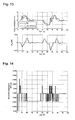
- the illustration shows that the initial step size is determined by the timing of the trajectory generation and then increases linearly within the prediction horizon.
- FIG. 11 shows the speed of the load, once as it is specified by the crane operator by means of an input element, and once as it is specified via the inventive path planning module by means of optimal control as a target trajectory.
- the limitations of the system are taken into account, so that the upper limit for the speed of the load depends on the radial load position, since the geometry of the boom and the luffing cylinder allow different maximum speeds at different boom positions. For the maximum acceleration, however, a constant restriction is given.
- FIG. 12a now compares this desired trajectory with the measured speed of the load.
- the regulation according to the invention follows the desired trajectory, the path planning module compensating for uncertainties in the model by model-based path planning. This results in a fast and subdued movement the load without significant overshoots.
- FIG. 12b then shows the corresponding trajectory of the load position.
- the control according to the invention damps the spherical oscillations of the load by corresponding compensating movements of the boom during and at the end of each maneuver. This is in FIG. 13 shown, from which the counter-movements carried out by the cantilever tip arise, which counteract the vibration of the load. This allows the rope angle to be limited to less than 3 °.
- the computing time required for the online calculation of the optimal solution problem in the path planning module is in FIG. 14 shown. This results in computing times between 54 msec and 66 msec. Decisive for this extremely short response of the path planning to specifications of the crane operator is on the one hand the fast solvability by the downstream linear distance of non-linear control and non-linear crane system, and within the prediction horizon increasing length of the intervals between the bases of the prediction.
Landscapes
- Engineering & Computer Science (AREA)
- Mechanical Engineering (AREA)
- Automation & Control Theory (AREA)
- Control And Safety Of Cranes (AREA)
Priority Applications (1)
| Application Number | Priority Date | Filing Date | Title |
|---|---|---|---|
| EP12004726.1A EP2502871B1 (fr) | 2007-05-16 | 2008-04-30 | Commande de grue, grue et procédé |
Applications Claiming Priority (2)
| Application Number | Priority Date | Filing Date | Title |
|---|---|---|---|
| DE102007023027 | 2007-05-16 | ||
| DE102007039408A DE102007039408A1 (de) | 2007-05-16 | 2007-08-21 | Kransteuerung, Kran und Verfahren |
Related Child Applications (2)
| Application Number | Title | Priority Date | Filing Date |
|---|---|---|---|
| EP12004726.1A Division-Into EP2502871B1 (fr) | 2007-05-16 | 2008-04-30 | Commande de grue, grue et procédé |
| EP12004726.1A Division EP2502871B1 (fr) | 2007-05-16 | 2008-04-30 | Commande de grue, grue et procédé |
Publications (4)
| Publication Number | Publication Date |
|---|---|
| EP1992583A2 true EP1992583A2 (fr) | 2008-11-19 |
| EP1992583A3 EP1992583A3 (fr) | 2012-07-18 |
| EP1992583B1 EP1992583B1 (fr) | 2015-01-28 |
| EP1992583B2 EP1992583B2 (fr) | 2023-11-22 |
Family
ID=39577835
Family Applications (1)
| Application Number | Title | Priority Date | Filing Date |
|---|---|---|---|
| EP08008276.1A Active EP1992583B2 (fr) | 2007-05-16 | 2008-04-30 | Commande de grue, grue et procédé |
Country Status (1)
| Country | Link |
|---|---|
| EP (1) | EP1992583B2 (fr) |
Cited By (10)
| Publication number | Priority date | Publication date | Assignee | Title |
|---|---|---|---|---|
| CN101898727B (zh) * | 2009-05-27 | 2012-10-10 | 无锡港盛港口机械有限公司 | 起重机的超负荷装置 |
| CN106006417A (zh) * | 2016-08-17 | 2016-10-12 | 徐州重型机械有限公司 | 一种起重机吊钩摆动的监控系统及方法 |
| CN113753752A (zh) * | 2021-08-20 | 2021-12-07 | 天津港太平洋国际集装箱码头有限公司 | 一种吊具的防摇方法、装置、系统以及起重设备 |
| US20210387833A1 (en) * | 2018-10-12 | 2021-12-16 | Indexator Rotator Systems Ab | Arrangement for controlling a rotator by image sensing means |
| CN113950458A (zh) * | 2019-04-12 | 2022-01-18 | 建筑机器人股份有限公司 | 用于控制悬挂在缆索上的载荷的设备 |
| CN114408755A (zh) * | 2022-01-21 | 2022-04-29 | 上海振华重工(集团)股份有限公司 | 一种吊具位姿控制方法、系统、设备及程序产品 |
| CN115057355A (zh) * | 2022-07-15 | 2022-09-16 | 河北工业大学 | 变绳长双摆桥式吊车自抗扰控制方法及系统 |
| CN115072564A (zh) * | 2022-06-24 | 2022-09-20 | 大连美恒时代科技有限公司 | 一种自动跟踪起重机吊载位置的装置及方法 |
| CN115784030A (zh) * | 2022-12-01 | 2023-03-14 | 郑州凯雪冷链股份有限公司 | 一种智能冷库库板现场吊装装置 |
| WO2024217734A1 (fr) * | 2023-04-18 | 2024-10-24 | Liebherr-Werk Nenzing Gmbh | Procédé, système et programme informatique pour déplacer une charge au moyen d'une pluralité de grues |
Families Citing this family (1)
| Publication number | Priority date | Publication date | Assignee | Title |
|---|---|---|---|---|
| DE102020120699A1 (de) | 2020-08-05 | 2022-02-10 | Konecranes Global Corporation | Auslegerdrehkran mit einer Kamera sowie Verfahren zur Reduzierung von Lastpendelungen im Kranbetrieb |
Citations (6)
| Publication number | Priority date | Publication date | Assignee | Title |
|---|---|---|---|---|
| JPH04223993A (ja) | 1990-09-21 | 1992-08-13 | Kobe Steel Ltd | クレーンにおけるロープの振れ角検出装置 |
| DE10029579A1 (de) | 2000-06-15 | 2002-01-03 | Hofer Eberhard | Verfahren zur Orientierung der Last in Krananlagen |
| DE10064182A1 (de) | 2000-10-19 | 2002-05-08 | Liebherr Werk Nenzing | Kran oder Bagger zum Umschlagen von einer an einem Lastseil hängenden Last mit Lastpendelungsdämpfung |
| DE10324692A1 (de) | 2003-05-30 | 2005-01-05 | Liebherr-Werk Nenzing Gmbh, Nenzing | Kran oder Bagger zum Umschlagen von einer an einem Lastseil hängenden Last mit optimierter Bewegungsführung |
| DE102006033277A1 (de) | 2006-07-18 | 2008-02-07 | Liebherr-Werk Nenzing Gmbh, Nenzing | Verfahren zum Steuern der Orientierung einer Kranlast |
| DE102006048988A1 (de) | 2006-10-17 | 2008-04-24 | Liebherr-Werk Nenzing Gmbh, Nenzing | Steuerungssystem für einen Auslegerkran |
Family Cites Families (3)
| Publication number | Priority date | Publication date | Assignee | Title |
|---|---|---|---|---|
| FR2445291A1 (fr) * | 1978-12-28 | 1980-07-25 | Casteran Jean | Systeme de suspension d'un fardeau, notamment pour grue |
| US5730305A (en) * | 1988-12-27 | 1998-03-24 | Kato Works Co., Ltd. | Crane safety apparatus |
| FI117969B (fi) * | 2004-09-01 | 2007-05-15 | Kalmar Ind Oy Ab | Laitteisto ja menetelmä kontin kiertoheilahdusliikkeen pysäyttämiseksi |
-
2008
- 2008-04-30 EP EP08008276.1A patent/EP1992583B2/fr active Active
Patent Citations (6)
| Publication number | Priority date | Publication date | Assignee | Title |
|---|---|---|---|---|
| JPH04223993A (ja) | 1990-09-21 | 1992-08-13 | Kobe Steel Ltd | クレーンにおけるロープの振れ角検出装置 |
| DE10029579A1 (de) | 2000-06-15 | 2002-01-03 | Hofer Eberhard | Verfahren zur Orientierung der Last in Krananlagen |
| DE10064182A1 (de) | 2000-10-19 | 2002-05-08 | Liebherr Werk Nenzing | Kran oder Bagger zum Umschlagen von einer an einem Lastseil hängenden Last mit Lastpendelungsdämpfung |
| DE10324692A1 (de) | 2003-05-30 | 2005-01-05 | Liebherr-Werk Nenzing Gmbh, Nenzing | Kran oder Bagger zum Umschlagen von einer an einem Lastseil hängenden Last mit optimierter Bewegungsführung |
| DE102006033277A1 (de) | 2006-07-18 | 2008-02-07 | Liebherr-Werk Nenzing Gmbh, Nenzing | Verfahren zum Steuern der Orientierung einer Kranlast |
| DE102006048988A1 (de) | 2006-10-17 | 2008-04-24 | Liebherr-Werk Nenzing Gmbh, Nenzing | Steuerungssystem für einen Auslegerkran |
Cited By (12)
| Publication number | Priority date | Publication date | Assignee | Title |
|---|---|---|---|---|
| CN101898727B (zh) * | 2009-05-27 | 2012-10-10 | 无锡港盛港口机械有限公司 | 起重机的超负荷装置 |
| CN106006417A (zh) * | 2016-08-17 | 2016-10-12 | 徐州重型机械有限公司 | 一种起重机吊钩摆动的监控系统及方法 |
| US20210387833A1 (en) * | 2018-10-12 | 2021-12-16 | Indexator Rotator Systems Ab | Arrangement for controlling a rotator by image sensing means |
| CN113950458A (zh) * | 2019-04-12 | 2022-01-18 | 建筑机器人股份有限公司 | 用于控制悬挂在缆索上的载荷的设备 |
| CN113950458B (zh) * | 2019-04-12 | 2024-06-07 | 建筑机器人股份有限公司 | 用于控制悬挂在缆索上的载荷的设备 |
| CN113753752A (zh) * | 2021-08-20 | 2021-12-07 | 天津港太平洋国际集装箱码头有限公司 | 一种吊具的防摇方法、装置、系统以及起重设备 |
| CN114408755A (zh) * | 2022-01-21 | 2022-04-29 | 上海振华重工(集团)股份有限公司 | 一种吊具位姿控制方法、系统、设备及程序产品 |
| CN115072564A (zh) * | 2022-06-24 | 2022-09-20 | 大连美恒时代科技有限公司 | 一种自动跟踪起重机吊载位置的装置及方法 |
| CN115057355A (zh) * | 2022-07-15 | 2022-09-16 | 河北工业大学 | 变绳长双摆桥式吊车自抗扰控制方法及系统 |
| CN115057355B (zh) * | 2022-07-15 | 2024-05-24 | 河北工业大学 | 变绳长双摆桥式吊车自抗扰控制方法及系统 |
| CN115784030A (zh) * | 2022-12-01 | 2023-03-14 | 郑州凯雪冷链股份有限公司 | 一种智能冷库库板现场吊装装置 |
| WO2024217734A1 (fr) * | 2023-04-18 | 2024-10-24 | Liebherr-Werk Nenzing Gmbh | Procédé, système et programme informatique pour déplacer une charge au moyen d'une pluralité de grues |
Also Published As
| Publication number | Publication date |
|---|---|
| EP1992583B1 (fr) | 2015-01-28 |
| EP1992583A3 (fr) | 2012-07-18 |
| EP1992583B2 (fr) | 2023-11-22 |
Similar Documents
| Publication | Publication Date | Title |
|---|---|---|
| EP2502871B1 (fr) | Commande de grue, grue et procédé | |
| EP1992583B1 (fr) | Grue avec commande de grue | |
| EP3784616B1 (fr) | Grue et procédé pour commander une grue de ce type | |
| EP3649072B1 (fr) | Grue et procédé de commande d'une telle grue | |
| EP4013713B1 (fr) | Grue et procédé de commande d'une telle grue | |
| EP2272784B1 (fr) | Grue pour envelopper une charge suspendue à un câble porteur | |
| EP2298687B1 (fr) | Système de détection de la masse de charge d'une charge suspendue à une corde de levage de grue | |
| EP2272785B1 (fr) | Procédé de commande d'un entraînement de grue | |
| DE69606974T2 (de) | Verfahren und vorrichtung zum steuern des lasttragelementes und last von einem kran | |
| EP3408208B1 (fr) | Grue et procédé de commande de ladite grue | |
| DE102014008094A1 (de) | Verfahren zum Steuern der Ausrichtung einer Kranlast und Auslegekran | |
| AT520008B1 (de) | Verfahren zum Dämpfen von Drehschwingungen eines Lastaufnahmeelements einer Hebeeinrichtung | |
| DE102006048988A1 (de) | Steuerungssystem für einen Auslegerkran | |
| EP2878566B1 (fr) | Procédé d'influence d'un mouvement d'une charge logée au niveau d'une grue | |
| WO2009030586A1 (fr) | Dispositif de régulation destiné à atténuer les mouvements pendulaires d'une charge suspendue à un câble | |
| DE102015100669A1 (de) | Anti-pendel-steuerverfahren mit einstellbarer unterstützung für den transport einer schwebenden last | |
| EP3428112A1 (fr) | Palan, en particulier une grue mobile ou une pelleteuse à câbles, doté d'un dispositif de surveillance du processus de dressage et d'enlèvement d'un système de rampe et procédé correspondant | |
| DE10029579B4 (de) | Verfahren zur Orientierung der Last in Krananlagen | |
| DE202022003151U1 (de) | Turmdrehkran und Steuerungseinheit zum Betreiben eines Turmdrehkrans, Laufkatze und Katzfahrwerk | |
| EP2878567A1 (fr) | Procédé de détermination d'au moins un angle d'oscillation d'une charge absorbée par un dispositif de transport de charges et procédé d'amortissement de mouvements d'oscillation de la charge |
Legal Events
| Date | Code | Title | Description |
|---|---|---|---|
| PUAI | Public reference made under article 153(3) epc to a published international application that has entered the european phase |
Free format text: ORIGINAL CODE: 0009012 |
|
| AK | Designated contracting states |
Kind code of ref document: A2 Designated state(s): AT BE BG CH CY CZ DE DK EE ES FI FR GB GR HR HU IE IS IT LI LT LU LV MC MT NL NO PL PT RO SE SI SK TR |
|
| AX | Request for extension of the european patent |
Extension state: AL BA MK RS |
|
| PUAL | Search report despatched |
Free format text: ORIGINAL CODE: 0009013 |
|
| AK | Designated contracting states |
Kind code of ref document: A3 Designated state(s): AT BE BG CH CY CZ DE DK EE ES FI FR GB GR HR HU IE IS IT LI LT LU LV MC MT NL NO PL PT RO SE SI SK TR |
|
| AX | Request for extension of the european patent |
Extension state: AL BA MK RS |
|
| RIC1 | Information provided on ipc code assigned before grant |
Ipc: B66C 13/46 20060101ALI20120613BHEP Ipc: B66C 13/06 20060101ALI20120613BHEP Ipc: B66C 13/08 20060101AFI20120613BHEP |
|
| 17P | Request for examination filed |
Effective date: 20130117 |
|
| AKX | Designation fees paid |
Designated state(s): AT BE BG CH CY CZ DE DK EE ES FI FR GB GR HR HU IE IS IT LI LT LU LV MC MT NL NO PL PT RO SE SI SK TR |
|
| 17Q | First examination report despatched |
Effective date: 20130717 |
|
| TPAC | Observations filed by third parties |
Free format text: ORIGINAL CODE: EPIDOSNTIPA |
|
| GRAP | Despatch of communication of intention to grant a patent |
Free format text: ORIGINAL CODE: EPIDOSNIGR1 |
|
| INTG | Intention to grant announced |
Effective date: 20141014 |
|
| GRAS | Grant fee paid |
Free format text: ORIGINAL CODE: EPIDOSNIGR3 |
|
| GRAA | (expected) grant |
Free format text: ORIGINAL CODE: 0009210 |
|
| AK | Designated contracting states |
Kind code of ref document: B1 Designated state(s): AT BE BG CH CY CZ DE DK EE ES FI FR GB GR HR HU IE IS IT LI LT LU LV MC MT NL NO PL PT RO SE SI SK TR |
|
| REG | Reference to a national code |
Ref country code: GB Ref legal event code: FG4D Free format text: NOT ENGLISH |
|
| REG | Reference to a national code |
Ref country code: CH Ref legal event code: EP |
|
| REG | Reference to a national code |
Ref country code: IE Ref legal event code: FG4D Free format text: LANGUAGE OF EP DOCUMENT: GERMAN |
|
| REG | Reference to a national code |
Ref country code: ES Ref legal event code: FG2A Ref document number: 2531374 Country of ref document: ES Kind code of ref document: T3 Effective date: 20150313 |
|
| REG | Reference to a national code |
Ref country code: AT Ref legal event code: REF Ref document number: 708150 Country of ref document: AT Kind code of ref document: T Effective date: 20150315 |
|
| REG | Reference to a national code |
Ref country code: DE Ref legal event code: R096 Ref document number: 502008012640 Country of ref document: DE Effective date: 20150319 |
|
| REG | Reference to a national code |
Ref country code: FR Ref legal event code: PLFP Year of fee payment: 8 |
|
| REG | Reference to a national code |
Ref country code: NL Ref legal event code: T3 |
|
| REG | Reference to a national code |
Ref country code: LT Ref legal event code: MG4D |
|
| PG25 | Lapsed in a contracting state [announced via postgrant information from national office to epo] |
Ref country code: FI Free format text: LAPSE BECAUSE OF FAILURE TO SUBMIT A TRANSLATION OF THE DESCRIPTION OR TO PAY THE FEE WITHIN THE PRESCRIBED TIME-LIMIT Effective date: 20150128 Ref country code: NO Free format text: LAPSE BECAUSE OF FAILURE TO SUBMIT A TRANSLATION OF THE DESCRIPTION OR TO PAY THE FEE WITHIN THE PRESCRIBED TIME-LIMIT Effective date: 20150428 Ref country code: LT Free format text: LAPSE BECAUSE OF FAILURE TO SUBMIT A TRANSLATION OF THE DESCRIPTION OR TO PAY THE FEE WITHIN THE PRESCRIBED TIME-LIMIT Effective date: 20150128 Ref country code: SE Free format text: LAPSE BECAUSE OF FAILURE TO SUBMIT A TRANSLATION OF THE DESCRIPTION OR TO PAY THE FEE WITHIN THE PRESCRIBED TIME-LIMIT Effective date: 20150128 Ref country code: HR Free format text: LAPSE BECAUSE OF FAILURE TO SUBMIT A TRANSLATION OF THE DESCRIPTION OR TO PAY THE FEE WITHIN THE PRESCRIBED TIME-LIMIT Effective date: 20150128 Ref country code: BG Free format text: LAPSE BECAUSE OF FAILURE TO SUBMIT A TRANSLATION OF THE DESCRIPTION OR TO PAY THE FEE WITHIN THE PRESCRIBED TIME-LIMIT Effective date: 20150428 |
|
| PG25 | Lapsed in a contracting state [announced via postgrant information from national office to epo] |
Ref country code: LV Free format text: LAPSE BECAUSE OF FAILURE TO SUBMIT A TRANSLATION OF THE DESCRIPTION OR TO PAY THE FEE WITHIN THE PRESCRIBED TIME-LIMIT Effective date: 20150128 Ref country code: IS Free format text: LAPSE BECAUSE OF FAILURE TO SUBMIT A TRANSLATION OF THE DESCRIPTION OR TO PAY THE FEE WITHIN THE PRESCRIBED TIME-LIMIT Effective date: 20150528 Ref country code: PL Free format text: LAPSE BECAUSE OF FAILURE TO SUBMIT A TRANSLATION OF THE DESCRIPTION OR TO PAY THE FEE WITHIN THE PRESCRIBED TIME-LIMIT Effective date: 20150128 Ref country code: GR Free format text: LAPSE BECAUSE OF FAILURE TO SUBMIT A TRANSLATION OF THE DESCRIPTION OR TO PAY THE FEE WITHIN THE PRESCRIBED TIME-LIMIT Effective date: 20150429 |
|
| REG | Reference to a national code |
Ref country code: DE Ref legal event code: R026 Ref document number: 502008012640 Country of ref document: DE |
|
| PG25 | Lapsed in a contracting state [announced via postgrant information from national office to epo] |
Ref country code: RO Free format text: LAPSE BECAUSE OF FAILURE TO SUBMIT A TRANSLATION OF THE DESCRIPTION OR TO PAY THE FEE WITHIN THE PRESCRIBED TIME-LIMIT Effective date: 20150128 Ref country code: CZ Free format text: LAPSE BECAUSE OF FAILURE TO SUBMIT A TRANSLATION OF THE DESCRIPTION OR TO PAY THE FEE WITHIN THE PRESCRIBED TIME-LIMIT Effective date: 20150128 Ref country code: EE Free format text: LAPSE BECAUSE OF FAILURE TO SUBMIT A TRANSLATION OF THE DESCRIPTION OR TO PAY THE FEE WITHIN THE PRESCRIBED TIME-LIMIT Effective date: 20150128 Ref country code: SK Free format text: LAPSE BECAUSE OF FAILURE TO SUBMIT A TRANSLATION OF THE DESCRIPTION OR TO PAY THE FEE WITHIN THE PRESCRIBED TIME-LIMIT Effective date: 20150128 Ref country code: DK Free format text: LAPSE BECAUSE OF FAILURE TO SUBMIT A TRANSLATION OF THE DESCRIPTION OR TO PAY THE FEE WITHIN THE PRESCRIBED TIME-LIMIT Effective date: 20150128 |
|
| PLBI | Opposition filed |
Free format text: ORIGINAL CODE: 0009260 |
|
| PG25 | Lapsed in a contracting state [announced via postgrant information from national office to epo] |
Ref country code: LU Free format text: LAPSE BECAUSE OF FAILURE TO SUBMIT A TRANSLATION OF THE DESCRIPTION OR TO PAY THE FEE WITHIN THE PRESCRIBED TIME-LIMIT Effective date: 20150430 Ref country code: MC Free format text: LAPSE BECAUSE OF FAILURE TO SUBMIT A TRANSLATION OF THE DESCRIPTION OR TO PAY THE FEE WITHIN THE PRESCRIBED TIME-LIMIT Effective date: 20150128 |
|
| REG | Reference to a national code |
Ref country code: CH Ref legal event code: PL |
|
| 26 | Opposition filed |
Opponent name: TEREX MHPS GMBH Effective date: 20151026 |
|
| PLAX | Notice of opposition and request to file observation + time limit sent |
Free format text: ORIGINAL CODE: EPIDOSNOBS2 |
|
| GBPC | Gb: european patent ceased through non-payment of renewal fee |
Effective date: 20150430 |
|
| REG | Reference to a national code |
Ref country code: IE Ref legal event code: MM4A |
|
| PG25 | Lapsed in a contracting state [announced via postgrant information from national office to epo] |
Ref country code: CH Free format text: LAPSE BECAUSE OF NON-PAYMENT OF DUE FEES Effective date: 20150430 Ref country code: GB Free format text: LAPSE BECAUSE OF NON-PAYMENT OF DUE FEES Effective date: 20150430 Ref country code: LI Free format text: LAPSE BECAUSE OF NON-PAYMENT OF DUE FEES Effective date: 20150430 |
|
| PG25 | Lapsed in a contracting state [announced via postgrant information from national office to epo] |
Ref country code: SI Free format text: LAPSE BECAUSE OF FAILURE TO SUBMIT A TRANSLATION OF THE DESCRIPTION OR TO PAY THE FEE WITHIN THE PRESCRIBED TIME-LIMIT Effective date: 20150128 |
|
| PLAF | Information modified related to communication of a notice of opposition and request to file observations + time limit |
Free format text: ORIGINAL CODE: EPIDOSCOBS2 |
|
| REG | Reference to a national code |
Ref country code: FR Ref legal event code: PLFP Year of fee payment: 9 |
|
| PG25 | Lapsed in a contracting state [announced via postgrant information from national office to epo] |
Ref country code: IE Free format text: LAPSE BECAUSE OF NON-PAYMENT OF DUE FEES Effective date: 20150430 |
|
| PLBB | Reply of patent proprietor to notice(s) of opposition received |
Free format text: ORIGINAL CODE: EPIDOSNOBS3 |
|
| REG | Reference to a national code |
Ref country code: AT Ref legal event code: MM01 Ref document number: 708150 Country of ref document: AT Kind code of ref document: T Effective date: 20150430 |
|
| PG25 | Lapsed in a contracting state [announced via postgrant information from national office to epo] |
Ref country code: AT Free format text: LAPSE BECAUSE OF NON-PAYMENT OF DUE FEES Effective date: 20150430 |
|
| PG25 | Lapsed in a contracting state [announced via postgrant information from national office to epo] |
Ref country code: MT Free format text: LAPSE BECAUSE OF FAILURE TO SUBMIT A TRANSLATION OF THE DESCRIPTION OR TO PAY THE FEE WITHIN THE PRESCRIBED TIME-LIMIT Effective date: 20150128 |
|
| REG | Reference to a national code |
Ref country code: FR Ref legal event code: PLFP Year of fee payment: 10 |
|
| PG25 | Lapsed in a contracting state [announced via postgrant information from national office to epo] |
Ref country code: HU Free format text: LAPSE BECAUSE OF FAILURE TO SUBMIT A TRANSLATION OF THE DESCRIPTION OR TO PAY THE FEE WITHIN THE PRESCRIBED TIME-LIMIT; INVALID AB INITIO Effective date: 20080430 |
|
| PG25 | Lapsed in a contracting state [announced via postgrant information from national office to epo] |
Ref country code: CY Free format text: LAPSE BECAUSE OF FAILURE TO SUBMIT A TRANSLATION OF THE DESCRIPTION OR TO PAY THE FEE WITHIN THE PRESCRIBED TIME-LIMIT Effective date: 20150128 |
|
| PG25 | Lapsed in a contracting state [announced via postgrant information from national office to epo] |
Ref country code: PT Free format text: LAPSE BECAUSE OF FAILURE TO SUBMIT A TRANSLATION OF THE DESCRIPTION OR TO PAY THE FEE WITHIN THE PRESCRIBED TIME-LIMIT Effective date: 20150528 |
|
| PG25 | Lapsed in a contracting state [announced via postgrant information from national office to epo] |
Ref country code: TR Free format text: LAPSE BECAUSE OF FAILURE TO SUBMIT A TRANSLATION OF THE DESCRIPTION OR TO PAY THE FEE WITHIN THE PRESCRIBED TIME-LIMIT Effective date: 20150128 |
|
| PLAB | Opposition data, opponent's data or that of the opponent's representative modified |
Free format text: ORIGINAL CODE: 0009299OPPO |
|
| PLAB | Opposition data, opponent's data or that of the opponent's representative modified |
Free format text: ORIGINAL CODE: 0009299OPPO |
|
| R26 | Opposition filed (corrected) |
Opponent name: DEMAG CRANES & COMPONENTS GMBH Effective date: 20151026 |
|
| R26 | Opposition filed (corrected) |
Opponent name: DEMAG CRANES & COMPONENTS GMBH Effective date: 20151026 |
|
| REG | Reference to a national code |
Ref country code: FR Ref legal event code: PLFP Year of fee payment: 11 |
|
| APBM | Appeal reference recorded |
Free format text: ORIGINAL CODE: EPIDOSNREFNO |
|
| APBP | Date of receipt of notice of appeal recorded |
Free format text: ORIGINAL CODE: EPIDOSNNOA2O |
|
| APAH | Appeal reference modified |
Free format text: ORIGINAL CODE: EPIDOSCREFNO |
|
| APBQ | Date of receipt of statement of grounds of appeal recorded |
Free format text: ORIGINAL CODE: EPIDOSNNOA3O |
|
| PGFP | Annual fee paid to national office [announced via postgrant information from national office to epo] |
Ref country code: NL Payment date: 20200424 Year of fee payment: 13 |
|
| PGFP | Annual fee paid to national office [announced via postgrant information from national office to epo] |
Ref country code: IT Payment date: 20200430 Year of fee payment: 13 |
|
| APBU | Appeal procedure closed |
Free format text: ORIGINAL CODE: EPIDOSNNOA9O |
|
| REG | Reference to a national code |
Ref country code: NL Ref legal event code: MM Effective date: 20210501 |
|
| PLAY | Examination report in opposition despatched + time limit |
Free format text: ORIGINAL CODE: EPIDOSNORE2 |
|
| PG25 | Lapsed in a contracting state [announced via postgrant information from national office to epo] |
Ref country code: NL Free format text: LAPSE BECAUSE OF NON-PAYMENT OF DUE FEES Effective date: 20210501 |
|
| PLBC | Reply to examination report in opposition received |
Free format text: ORIGINAL CODE: EPIDOSNORE3 |
|
| PLAY | Examination report in opposition despatched + time limit |
Free format text: ORIGINAL CODE: EPIDOSNORE2 |
|
| PG25 | Lapsed in a contracting state [announced via postgrant information from national office to epo] |
Ref country code: IT Free format text: LAPSE BECAUSE OF NON-PAYMENT OF DUE FEES Effective date: 20200430 |
|
| P01 | Opt-out of the competence of the unified patent court (upc) registered |
Effective date: 20230630 |
|
| PUAH | Patent maintained in amended form |
Free format text: ORIGINAL CODE: 0009272 |
|
| STAA | Information on the status of an ep patent application or granted ep patent |
Free format text: STATUS: PATENT MAINTAINED AS AMENDED |
|
| 27A | Patent maintained in amended form |
Effective date: 20231122 |
|
| AK | Designated contracting states |
Kind code of ref document: B2 Designated state(s): AT BE BG CH CY CZ DE DK EE ES FI FR GB GR HR HU IE IS IT LI LT LU LV MC MT NL NO PL PT RO SE SI SK TR |
|
| REG | Reference to a national code |
Ref country code: DE Ref legal event code: R102 Ref document number: 502008012640 Country of ref document: DE |
|
| REG | Reference to a national code |
Ref country code: ES Ref legal event code: DC2A Ref document number: 2531374 Country of ref document: ES Kind code of ref document: T5 Effective date: 20240613 |
|
| PGFP | Annual fee paid to national office [announced via postgrant information from national office to epo] |
Ref country code: DE Payment date: 20250430 Year of fee payment: 18 |
|
| PGFP | Annual fee paid to national office [announced via postgrant information from national office to epo] |
Ref country code: ES Payment date: 20250505 Year of fee payment: 18 |
|
| PGFP | Annual fee paid to national office [announced via postgrant information from national office to epo] |
Ref country code: BE Payment date: 20250426 Year of fee payment: 18 |
|
| PGFP | Annual fee paid to national office [announced via postgrant information from national office to epo] |
Ref country code: FR Payment date: 20250426 Year of fee payment: 18 |