EP1992726A1 - Machine à coudre - Google Patents
Machine à coudre Download PDFInfo
- Publication number
- EP1992726A1 EP1992726A1 EP08007802A EP08007802A EP1992726A1 EP 1992726 A1 EP1992726 A1 EP 1992726A1 EP 08007802 A EP08007802 A EP 08007802A EP 08007802 A EP08007802 A EP 08007802A EP 1992726 A1 EP1992726 A1 EP 1992726A1
- Authority
- EP
- European Patent Office
- Prior art keywords
- counter
- knife
- blade
- sewing machine
- counter knife
- Prior art date
- Legal status (The legal status is an assumption and is not a legal conclusion. Google has not performed a legal analysis and makes no representation as to the accuracy of the status listed.)
- Withdrawn
Links
- 238000009958 sewing Methods 0.000 title claims abstract description 30
- 239000000463 material Substances 0.000 claims abstract description 8
- 239000011343 solid material Substances 0.000 claims abstract description 4
- 229920000742 Cotton Polymers 0.000 abstract 1
- 230000015572 biosynthetic process Effects 0.000 description 6
- 239000004744 fabric Substances 0.000 description 6
- 229910000997 High-speed steel Inorganic materials 0.000 description 1
- 230000000295 complement effect Effects 0.000 description 1
- 238000001514 detection method Methods 0.000 description 1
- 238000009966 trimming Methods 0.000 description 1
Images



Classifications
-
- D—TEXTILES; PAPER
- D05—SEWING; EMBROIDERING; TUFTING
- D05B—SEWING
- D05B37/00—Devices incorporated in sewing machines for slitting, grooving, or cutting
- D05B37/04—Cutting devices
-
- D—TEXTILES; PAPER
- D05—SEWING; EMBROIDERING; TUFTING
- D05B—SEWING
- D05B37/00—Devices incorporated in sewing machines for slitting, grooving, or cutting
-
- D—TEXTILES; PAPER
- D05—SEWING; EMBROIDERING; TUFTING
- D05B—SEWING
- D05B65/00—Devices for severing the needle or lower thread
Definitions
- the invention relates to a sewing machine with a knife according to the preamble of claim 1. Furthermore, the invention relates to a counter knife for such a sewing machine.
- counter knives can be made so symmetrical that a counter knife can be equipped with a plurality of counter knife cutting edges which successively, each time a cutting edge is worn, by changing the orientation of Counter knife can be used.
- the life and thus the cutting performance of the counter knife thus increases by a factor corresponding to the number of counter knife cutting edges provided. With a counter knife given quality thus increases its cutting performance accordingly.
- the counter-blade can be made of less wear-resistant material.
- the execution of the counter knife from für the counter knife receives the complete Integretusch the counter knife, which also has a life-increasing.
- a counter knife according to claim 2 has a cutting power which is at least four times higher than that of known counter knife material.
- Such a counter knife can be designed in particular as a rectangular blade plate.
- a counter knife according to claim 3 may be designed as a square blade plate, wherein all eight edges of this blade plate can be used as cutting edges.
- a counter knife holder according to claim 4 represents a structurally simple counter knife holder. A projection of the counter knife on the counter knife holder can be omitted.
- a clamping body according to claim 5 leads to a secure mounting of the counter knife.
- the clamping body may have recesses in order to keep free the sections involved counter knife surface sections.
- the counter knife may be clamped so that it cuts at a free, unclamped end.
- counter knife different thicknesses can be used, which can be used to shift the cutting position.
- a Nähgutschneide counter knife can be varied in particular by the thickness of the counter knife, the distance of the cut in the fabric from a seam sewn parallel to the cut.
- a sewing machine 1 has a base plate 2 with an upwardly extending therefrom stand 3 and an angled arm 4. The latter ends in a head 5.
- the base plate 2, the stator 3, the arm 4 and the head 5 are of a housing 6 of the sewing machine 1 surrounded.
- shaft is rotatably mounted. This drives in the head 5 via a crank mechanism in the head 5 axially slidably mounted needle bar 7 at.
- the needle bar 7 has at its lower end a needle 8. The latter can be moved up and down by the crank mechanism on a vertical axis.
- the needle 8 leads in an eye of a not shown coil supplied and also not shown needle thread.
- the base plate 2 carries a support plate 9, can be placed on the fabric for sewing with the sewing machine 1.
- the support plate 9 is in several parts. Part of the support plate 9 is a throat plate 10, with the Base plate 2 is screwed. The latter has a tap hole 11 for the passage of the needle 8. Furthermore, the throat plate 10 has a rectangular passage opening 12 through which an upper run of a lower feed wheel 13 passes.
- the lower Stoffschieberrad 13 is in a known manner in drive connection with a arranged below the base plate 2 drive shaft. To feed the material, the lower Stoffschieberrad 13 cooperates with an upper Stoffschieberrad 14.
- the throat plate 10 On the passage opening 12 horizontally opposite side of the needle hole 11, the throat plate 10 has a counter blade receptacle 15 for supporting a housing-fixed Nähgutschneid counter knife 16 of a Nähgutabschneiders 17.
- the counter blade 16 is made of high-speed steel.
- the counter-blade 15 is made of solid material without breakage, and therefore has no through-holes for the passage of fastening elements.
- a clamping body 18 For holding the counter blade 16, this is clamped by a clamping body 18 against the needle plate 10 as a base body in the counter blade holder 15.
- the clamping body 18 clamps the counter blade 16 in regions, so that a counter blade surface 19 of the counter blade 16 remains free on the side remote from the base body, ie the throat plate 10 side.
- the clamping body 18 is pressed against the counter blade 16 by two horizontally adjacent screws 20.
- the screws 20 pass through the needle plate 10 and are accessible via access holes 21 from the outside of the needle plate 10 ago.
- the counter-blade surface 19 includes a counter-blade cutting edge 23 with an upper-side end face 22.
- the edge angle is exactly 90 °.
- the counter knife 16 is formed as a square blade plate. Altogether there are eight similar counter knife cutting edges 23 in the counter knife 16, as in the Fig. 9 indicated.
- the counter-blade 16 can be supported in eight different orientations in the counter-blade holder 15, wherein in each of these eight orientations in each case a different one of the counter-blade cutting edges 23 is used.
- a knife 24 of the Nähgutabschneiders 17 cooperates.
- the knife 24 is moved up and down synchronously with the stitch formation via a screw jack.
- When cutting a knife surface 25 cooperates with the counter blade surface 19.
- the knife 24 is beveled towards the inlet side of the fabric, wherein the slope is complementary to an inclined portion 26 of the clamping body 18, which releases the counter blade surface 19.
- the counter knife holder 15 can support counter knife 16 different plate thickness. Depending on the thickness of the counter blade 16, the cutting plane of the knife 24 can be readjusted. The larger the plate thickness of the counter blade 16, the further, for example, the cut formed by the Nähgutabschneider 17 in the fabric spaced from the sewing machine parallel stitched seam.
- a displaceable plate member 27 of the support plate 9 is removed so that the screws 20 are accessible via the access holes 21.
- the clamp body 18 loosely screwed and the counter-blade 16 can be removed from the counter-knife holder 15 and used in another orientation again in this.
- the screws 20 are tightened again. Accordingly, a replacement of the counter blade 16 is moved against a new counter-blade of the same or different strength.
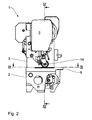
- a gripper 28 which is rotatable about a vertical gripper axis.
- a cup-shaped coil housing for receiving a Greiferfadenvorrates is stored.
- the latter is between a basic position shown in the drawing and a thread detection position about a pivot axis parallel to the gripper axis (see 31 in the Fig. 3 ) pivotable.
- the thread-pulling knife 30 has one in the view Fig. 3 reminiscent of a sickle basic shape, the free end extends in the basic position to the bobbin case of the gripper 28 around.
- a knife surface 32 of the thread-pulling knife 30 cooperates for thread trimming with a counter-knife surface 33 of a thread-cutting counter knife 34 fixed to the housing.
- the counter knife 34 has the shape of a rectangular plate, as in Fig. 10 shown.
- a counter knife cutting edge 35 is formed between the counter knife surface 33 and an end face 36 of the counter knife 34.
- the counter knife 34 has a total of four similar such counter knife cutting edges 35, as in the Fig. 10 indicated, depending on the orientation of the counter knife 34 in a counter knife holder 37 used comes.
- the counter knife holder 37 has a curved base body 38 which clamps the counter knife 34 against a housing-fixed clamping body 39.
- the position of the main body 38 relative to the frame or to the housing of the sewing machine 1 can be finely specified by means of adjusting screws 41.
- the clamping body 39 is fixed by a screw 40 which can be screwed into a thread fixed to the housing.
- the clamping with the housing-fixed body 38 and the clamping body 39 makes it possible to obtain a relative positioning of the blade surfaces 32, 33 to each other in the clamping of counter knives 34 of different thickness.
- the screw 41 is released and the clamping body 38 is moved away from the base body 39, so that the counter blade 34 is released.
- the counter knife 34 can then be removed and replaced in a new orientation or replaced with a new counter knife 34, so that a new counter knife cutting edge 35 can cooperate with the blade surface 32 of the thread trimmer.
Landscapes
- Engineering & Computer Science (AREA)
- Textile Engineering (AREA)
- Sewing Machines And Sewing (AREA)
Applications Claiming Priority (1)
| Application Number | Priority Date | Filing Date | Title |
|---|---|---|---|
| DE102007022818A DE102007022818A1 (de) | 2007-05-15 | 2007-05-15 | Nähmaschine |
Publications (1)
| Publication Number | Publication Date |
|---|---|
| EP1992726A1 true EP1992726A1 (fr) | 2008-11-19 |
Family
ID=39713924
Family Applications (1)
| Application Number | Title | Priority Date | Filing Date |
|---|---|---|---|
| EP08007802A Withdrawn EP1992726A1 (fr) | 2007-05-15 | 2008-04-23 | Machine à coudre |
Country Status (5)
| Country | Link |
|---|---|
| EP (1) | EP1992726A1 (fr) |
| JP (1) | JP2008284357A (fr) |
| KR (1) | KR20080101706A (fr) |
| CN (1) | CN101307534A (fr) |
| DE (1) | DE102007022818A1 (fr) |
Cited By (5)
| Publication number | Priority date | Publication date | Assignee | Title |
|---|---|---|---|---|
| JP2010119818A (ja) * | 2008-11-20 | 2010-06-03 | Yamato Sewing Mach Co Ltd | ミシンの生地切断装置 |
| CN102797121A (zh) * | 2012-08-24 | 2012-11-28 | 新杰克缝纫机股份有限公司 | 双针缝纫机之剪线刀具 |
| CN103510292A (zh) * | 2012-06-28 | 2014-01-15 | 星锐缝纫机(嘉兴)有限公司 | 具有电磁自动裁切装置的缝纫机 |
| CN105155144A (zh) * | 2015-09-28 | 2015-12-16 | 南京际华三五0三服装有限公司 | 双止口切割器 |
| EP3736369A1 (fr) | 2019-05-08 | 2020-11-11 | Dürkopp Adler AG | Machine à coudre ainsi que module de contre-lame pour une machine |
Families Citing this family (1)
| Publication number | Priority date | Publication date | Assignee | Title |
|---|---|---|---|---|
| TWI615522B (zh) * | 2016-11-29 | 2018-02-21 | 縫紉機之閘刀式切斷裝置 |
Citations (8)
| Publication number | Priority date | Publication date | Assignee | Title |
|---|---|---|---|---|
| DE3303034A1 (de) | 1983-01-29 | 1984-08-02 | Kochs Adler Ag, 4800 Bielefeld | Fadenabschneidvorrichtung fuer eine naehmaschine |
| DE8630911U1 (de) | 1986-11-18 | 1987-01-15 | Dürkoppwerke GmbH, 4800 Bielefeld | Fadenschneidvorrichtung an einer Doppelsteppstichnähmaschine mit einem in einer horizontalen Ebene umlaufenden Greifer |
| DE3621785A1 (de) * | 1986-06-28 | 1988-01-14 | Duerkoppwerke | Naehmaschine mit einer naehgut-beschneidvorrichtung |
| WO1995019245A1 (fr) * | 1994-01-13 | 1995-07-20 | Ralph's Industrial Sewing Machine Company | Bloc de coupe et support de lame de coupe fixe |
| EP0933461A2 (fr) | 1998-02-02 | 1999-08-04 | Johannes Sahl | Appareil auxiliaire pour machines à coudre pour couper l'ouvrage |
| DE19835500C1 (de) * | 1998-08-06 | 2000-03-16 | Duerkopp Adler Ag | Schneidvorrichtung zur Erzeugung einer Schlitzöffnung für ein Knopfloch |
| DE102004015813B3 (de) | 2004-03-31 | 2005-05-19 | Dürkopp Adler AG | Augen-Knopfloch-Nähmaschine |
| AT414129B (de) | 2002-06-07 | 2006-09-15 | Sahl Johannes | Nähmaschine zum verbinden zweier stofflagen durch eine flachnaht |
-
2007
- 2007-05-15 DE DE102007022818A patent/DE102007022818A1/de not_active Ceased
-
2008
- 2008-04-23 EP EP08007802A patent/EP1992726A1/fr not_active Withdrawn
- 2008-05-14 KR KR1020080044542A patent/KR20080101706A/ko not_active Withdrawn
- 2008-05-14 JP JP2008127063A patent/JP2008284357A/ja active Pending
- 2008-05-15 CN CNA2008100990383A patent/CN101307534A/zh active Pending
Patent Citations (8)
| Publication number | Priority date | Publication date | Assignee | Title |
|---|---|---|---|---|
| DE3303034A1 (de) | 1983-01-29 | 1984-08-02 | Kochs Adler Ag, 4800 Bielefeld | Fadenabschneidvorrichtung fuer eine naehmaschine |
| DE3621785A1 (de) * | 1986-06-28 | 1988-01-14 | Duerkoppwerke | Naehmaschine mit einer naehgut-beschneidvorrichtung |
| DE8630911U1 (de) | 1986-11-18 | 1987-01-15 | Dürkoppwerke GmbH, 4800 Bielefeld | Fadenschneidvorrichtung an einer Doppelsteppstichnähmaschine mit einem in einer horizontalen Ebene umlaufenden Greifer |
| WO1995019245A1 (fr) * | 1994-01-13 | 1995-07-20 | Ralph's Industrial Sewing Machine Company | Bloc de coupe et support de lame de coupe fixe |
| EP0933461A2 (fr) | 1998-02-02 | 1999-08-04 | Johannes Sahl | Appareil auxiliaire pour machines à coudre pour couper l'ouvrage |
| DE19835500C1 (de) * | 1998-08-06 | 2000-03-16 | Duerkopp Adler Ag | Schneidvorrichtung zur Erzeugung einer Schlitzöffnung für ein Knopfloch |
| AT414129B (de) | 2002-06-07 | 2006-09-15 | Sahl Johannes | Nähmaschine zum verbinden zweier stofflagen durch eine flachnaht |
| DE102004015813B3 (de) | 2004-03-31 | 2005-05-19 | Dürkopp Adler AG | Augen-Knopfloch-Nähmaschine |
Cited By (6)
| Publication number | Priority date | Publication date | Assignee | Title |
|---|---|---|---|---|
| JP2010119818A (ja) * | 2008-11-20 | 2010-06-03 | Yamato Sewing Mach Co Ltd | ミシンの生地切断装置 |
| CN103510292A (zh) * | 2012-06-28 | 2014-01-15 | 星锐缝纫机(嘉兴)有限公司 | 具有电磁自动裁切装置的缝纫机 |
| CN103510292B (zh) * | 2012-06-28 | 2015-06-17 | 星锐缝纫机(嘉兴)有限公司 | 具有电磁自动裁切装置的缝纫机 |
| CN102797121A (zh) * | 2012-08-24 | 2012-11-28 | 新杰克缝纫机股份有限公司 | 双针缝纫机之剪线刀具 |
| CN105155144A (zh) * | 2015-09-28 | 2015-12-16 | 南京际华三五0三服装有限公司 | 双止口切割器 |
| EP3736369A1 (fr) | 2019-05-08 | 2020-11-11 | Dürkopp Adler AG | Machine à coudre ainsi que module de contre-lame pour une machine |
Also Published As
| Publication number | Publication date |
|---|---|
| CN101307534A (zh) | 2008-11-19 |
| DE102007022818A1 (de) | 2008-11-20 |
| JP2008284357A (ja) | 2008-11-27 |
| KR20080101706A (ko) | 2008-11-21 |
Similar Documents
| Publication | Publication Date | Title |
|---|---|---|
| EP2593233B1 (fr) | Porte-couteau pour dispositifs de broyage | |
| DE102007022818A1 (de) | Nähmaschine | |
| DE2313717A1 (de) | Einrichtung zur herstellung von paspeloeffnungen in zuschnitteilen von bekleidungsstuecken | |
| EP2692925B1 (fr) | Couteau à tirer le fil pour une machine à coudre, module de coupe de fil et machine à coudre dotée d'un tel couteau à tirer le fil | |
| DE10123075C1 (de) | Doppelsteppstichnähmaschine mit einer Fadenabschneidvorrichtung | |
| DE822643C (de) | Naehmaschine, insbesondere zum Saeumen von Strumpfwaren | |
| DE3621785C2 (fr) | ||
| EP3736369B1 (fr) | Machine à coudre ainsi que module de contre-lame pour une machine | |
| DE19531727A1 (de) | Fadenabschneidvorrichtung für eine Nähmaschine | |
| DE102010014246B3 (de) | Drahtbearbeitungsmaschine | |
| DE1143695B (de) | Naehmaschine zum Herstellen einer UEberwendlichnaht und einer Befestigungsnaht | |
| EP2057309B1 (fr) | Convertisseur à buse rotative | |
| DE202008016612U1 (de) | Längsschneidemaschine mit variabler Einstellung der Messer-Schneidpunkte | |
| EP0670203B1 (fr) | Procede et dispositif de coupe de feuilles de papier assemblees dans une rame | |
| DE10351889B4 (de) | Fadenabschneider | |
| DE3612837C2 (fr) | ||
| EP2360305B1 (fr) | Procédé de commande d'une machine à coudre et machine à coudre | |
| DE2930415C2 (de) | Vorrichtung zum Andrücken des beweglichen Messers in einer Scheidvorrichtung für Erntemaschinen | |
| EP2529834A2 (fr) | Machine de coupe à tambour et boîte à couteaux pour une machine de ce type | |
| EP3321409B1 (fr) | Machine à coudre à deux aiguilles pourvue d'un ensemble de coupe de fil supérieur, et ensemble de couture de passepoil comprenant cette machine | |
| AT165608B (de) | Blindstich- und Pikiermaschine | |
| DE499500C (de) | Garnreiniger | |
| DE642612C (de) | Hilfsapparat fuer Naehmaschinen zur Herstellung von Teppichen | |
| DE665842C (de) | Maschine zum Beschneiden von Schuhteilen | |
| AT68267B (de) | Schiffchenstickmaschine. |
Legal Events
| Date | Code | Title | Description |
|---|---|---|---|
| PUAI | Public reference made under article 153(3) epc to a published international application that has entered the european phase |
Free format text: ORIGINAL CODE: 0009012 |
|
| AK | Designated contracting states |
Kind code of ref document: A1 Designated state(s): AT BE BG CH CY CZ DE DK EE ES FI FR GB GR HR HU IE IS IT LI LT LU LV MC MT NL NO PL PT RO SE SI SK TR |
|
| AX | Request for extension of the european patent |
Extension state: AL BA MK RS |
|
| AKX | Designation fees paid | ||
| STAA | Information on the status of an ep patent application or granted ep patent |
Free format text: STATUS: THE APPLICATION IS DEEMED TO BE WITHDRAWN |
|
| 18D | Application deemed to be withdrawn |
Effective date: 20090520 |
|
| REG | Reference to a national code |
Ref country code: DE Ref legal event code: 8566 |