EP1992744A2 - Vorrichtung zur Anbringung hydraulischer Ventile zur Steuerung von Arbeitsmaschinen - Google Patents
Vorrichtung zur Anbringung hydraulischer Ventile zur Steuerung von Arbeitsmaschinen Download PDFInfo
- Publication number
- EP1992744A2 EP1992744A2 EP08008705A EP08008705A EP1992744A2 EP 1992744 A2 EP1992744 A2 EP 1992744A2 EP 08008705 A EP08008705 A EP 08008705A EP 08008705 A EP08008705 A EP 08008705A EP 1992744 A2 EP1992744 A2 EP 1992744A2
- Authority
- EP
- European Patent Office
- Prior art keywords
- hydraulic
- valve
- upper swing
- sub
- main control
- Prior art date
- Legal status (The legal status is an assumption and is not a legal conclusion. Google has not performed a legal analysis and makes no representation as to the accuracy of the status listed.)
- Withdrawn
Links
- 238000010276 construction Methods 0.000 title description 2
- 239000012530 fluid Substances 0.000 claims abstract description 13
- 238000000034 method Methods 0.000 description 13
- 238000004519 manufacturing process Methods 0.000 description 5
- 238000007792 addition Methods 0.000 description 1
- 238000012986 modification Methods 0.000 description 1
- 230000004048 modification Effects 0.000 description 1
- 238000004904 shortening Methods 0.000 description 1
- 238000006467 substitution reaction Methods 0.000 description 1
Images


Classifications
-
- E—FIXED CONSTRUCTIONS
- E02—HYDRAULIC ENGINEERING; FOUNDATIONS; SOIL SHIFTING
- E02F—DREDGING; SOIL-SHIFTING
- E02F9/00—Component parts of dredgers or soil-shifting machines, not restricted to one of the kinds covered by groups E02F3/00 - E02F7/00
- E02F9/08—Superstructures; Supports for superstructures
- E02F9/0858—Arrangement of component parts installed on superstructures not otherwise provided for, e.g. electric components, fenders, air-conditioning units
- E02F9/0875—Arrangement of valve arrangements on superstructures
-
- E—FIXED CONSTRUCTIONS
- E02—HYDRAULIC ENGINEERING; FOUNDATIONS; SOIL SHIFTING
- E02F—DREDGING; SOIL-SHIFTING
- E02F9/00—Component parts of dredgers or soil-shifting machines, not restricted to one of the kinds covered by groups E02F3/00 - E02F7/00
-
- E—FIXED CONSTRUCTIONS
- E02—HYDRAULIC ENGINEERING; FOUNDATIONS; SOIL SHIFTING
- E02F—DREDGING; SOIL-SHIFTING
- E02F9/00—Component parts of dredgers or soil-shifting machines, not restricted to one of the kinds covered by groups E02F3/00 - E02F7/00
- E02F9/08—Superstructures; Supports for superstructures
-
- E—FIXED CONSTRUCTIONS
- E02—HYDRAULIC ENGINEERING; FOUNDATIONS; SOIL SHIFTING
- E02F—DREDGING; SOIL-SHIFTING
- E02F9/00—Component parts of dredgers or soil-shifting machines, not restricted to one of the kinds covered by groups E02F3/00 - E02F7/00
- E02F9/20—Drives; Control devices
- E02F9/22—Hydraulic or pneumatic drives
- E02F9/2264—Arrangements or adaptations of elements for hydraulic drives
- E02F9/2267—Valves or distributors
-
- E—FIXED CONSTRUCTIONS
- E02—HYDRAULIC ENGINEERING; FOUNDATIONS; SOIL SHIFTING
- E02F—DREDGING; SOIL-SHIFTING
- E02F9/00—Component parts of dredgers or soil-shifting machines, not restricted to one of the kinds covered by groups E02F3/00 - E02F7/00
- E02F9/20—Drives; Control devices
- E02F9/22—Hydraulic or pneumatic drives
- E02F9/2264—Arrangements or adaptations of elements for hydraulic drives
- E02F9/2275—Hoses and supports therefor and protection therefor
-
- Y—GENERAL TAGGING OF NEW TECHNOLOGICAL DEVELOPMENTS; GENERAL TAGGING OF CROSS-SECTIONAL TECHNOLOGIES SPANNING OVER SEVERAL SECTIONS OF THE IPC; TECHNICAL SUBJECTS COVERED BY FORMER USPC CROSS-REFERENCE ART COLLECTIONS [XRACs] AND DIGESTS
- Y10—TECHNICAL SUBJECTS COVERED BY FORMER USPC
- Y10T—TECHNICAL SUBJECTS COVERED BY FORMER US CLASSIFICATION
- Y10T29/00—Metal working
- Y10T29/53—Means to assemble or disassemble
- Y10T29/534—Multiple station assembly or disassembly apparatus
- Y10T29/53417—Means to fasten work parts together
Definitions
- the present invention relates to an apparatus for attachment of hydraulic valves for controlling working devices of heavy equipment, which can reduce a lead time for attaching and assembling a main control valve for controlling hydraulic fluid being fed from a hydraulic pump to drive the working devices such as a boom and so on, an accessory valve, and various kinds of valve blocks (hereinafter referred to as "hydraulic valves") for jointly connecting the respective valves with hydraulic piping (hydraulic hoses or hydraulic pipes), to an upper swing structure.
- hydraulic valves for jointly connecting the respective valves with hydraulic piping (hydraulic hoses or hydraulic pipes), to an upper swing structure.
- the present invention relates to an apparatus for attachment of hydraulic valves for controlling working devices of heavy equipment, which can reduce a lead time for assembly by improving assemblage and workability of the hydraulic valves through attachment of a sub-plate to an upper swing structure after the hydraulic valves are attached and assembled to the sub-plate.
- a general excavator includes a lower driving structure 1; an upper swing structure 2 mounted on the lower driving structure 1 and being swiveled in left and right directions; a cabin 3 and an engine room 4 mounted in front and in the rear of the upper swing structure 2; working devices 11 fixed to the upper swing structure 2, and including a boom 6 driven by a boom cylinder 5, an arm 8 driven by an arm cylinder 7, and a bucket 10 driven by a bucket cylinder 9; a main control valve 12 shifted in accordance with a user operation signal from an operation lever RCV, and including spools for controlling a supply amount and a flow direction of hydraulic fluid fed to the corresponding working devices 11 during the shifting of the main control valve; and a counterweight 13 attached to the rear of the upper swing structure 2 to valance the equipment.
- the main control valve 12 including spools for controlling hydraulic fluid being supplied to the working devices is installed in the center of the rear side of the upper swing structure 2, and an accessory valve including solenoid valves and so on are installed in a space adjacent to the main control valve 12.
- the main control valve 12 and the accessory valve 15 are jointly connected with each other through hydraulic hoses s or hydraulic pipes.
- the option valves 15 include a selector valve, a solenoid valve, a shuttle valve, valve blocks 16 (e.g. a confluence block, a drain block, and the like), an electric proportional control valve, and the like.
- the main control valve 12 and the accessory valve 15 are mounted in specified positions of the upper swing structure 2 that is put on an assembly line of the equipment, and then the valves are jointly connected with each other through the hydraulic hoses s.
- the length of the upper swing structure 2 is set to be shorter than that in general equipment in order to reduce the radius of swing.
- the main control valve 12 may be installed on the right side of a boom, and the accessory valve 15 may be installed in the neighborhood of the main control valve 12.
- the accessory valve 15 may be installed in the upper swing structure 2, and the valves are jointly connected with hydraulic hoses and so on.
- an object of the present invention is to provide an apparatus for attachment of hydraulic valves for controlling working devices of heavy equipment, which can reduce a manufacturing cost of the equipment by shortening a lead time for attaching and assembling the hydraulic valves to an upper swing structure through attachment of a sub-plate to the upper swing structure after the hydraulic valves are attached and assembled to the sub-plate, and improve the assemblage and workability of the hydraulic valves by facilitating the attachment and assembly work.
- an apparatus for attachment of hydraulic valves for controlling working devices of heavy equipment which includes a lower driving structure and an upper swing structure mounted on the lower driving structure and being swiveled in left and right directions; a cabin and an engine room mounted on the upper swing structure; working devices fixed to the upper swing structure, and including a boom, an arm, and a bucket driven by hydraulic cylinders; a main control valve shifted in accordance with an operation signal from an operation lever, and including spools for controlling a supply amount and a flow direction of hydraulic fluid fed to the corresponding working devices during the shifting of the main control valve; a sub-plate attached to a specified position of the upper swing structure; an accessory valve installed on the sub-plate and controlling hydraulic fluid fed to the main control valve; and valve blocks installed on the sub-plate and jointly connecting the main control valve and the accessory valve with hydraulic pipes; wherein the main control valve, the accessory valve, and the valve blocks are installed on the sub-plate, the respective valves are connected with the hydraulic pipes;
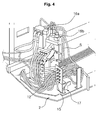
- an apparatus for attachment of hydraulic valves for controlling working devices of heavy equipment includes a lower driving structure 1, an upper swing structure 2 mounted on the lower driving structure 1 and being swiveled in left and right directions; a cabin 3 and an engine room 4 mounted on the upper swing structure 2; working devices 11 fixed to the upper swing structure 2, and including a boom 6, an arm 8, and a bucket 10 driven by hydraulic cylinders 5, 7, and 9; a main control valve (MCV) 12 shifted in accordance with an operation signal from an operation lever (RCV), and including spools for controlling a supply amount and a flow direction of hydraulic fluid fed to the corresponding working devices during the shifting of the main control valve; a sub-plate 17 attached to a specified position of the upper swing structure 2; an accessory valve 15 installed on the sub-plate 17 and controlling hydraulic fluid fed from a hydraulic pump (not illustrated) to the main control valve 12; and valve blocks 16a and 16b installed on the sub-plate 17 and jointly connecting the main control valve 12 and the accessory
- the hydraulic valves e.g. the main control valve 12, the accessory valve 15, and the valve blocks 16a and 16b
- the main control valve 12 for supplying the hydraulic fluid from the hydraulic pump to the working devices 11 or returning the hydraulic fluid to the hydraulic pump are installed on the sub-plate 17, the main control valve 12, the accessory valve 15, and the valve blocks 16a and 16b are jointly connected with the hydraulic hoses s. That is, a work process of installing the hydraulic valves 12, 15, 16a, and 16b on the sub-plate 17 and a work process of jointly connecting the hydraulic valves with the hydraulic hoses s are simultaneously performed as a single work process.
- the sub-plate As described above, after the attachment of the hydraulic valves to a specified position of the sub-plate 17 and the connection of the hydraulic valves with the hydraulic hoses s are performed, the sub-plate, to which the hydraulic valves are attached, is attached to a specified position of the upper swing structure 2 to complete the attachment and the assembly of the hydraulic valves to the upper swing structure 2.
- the corresponding work can be easily performed without being restricted in space, and thus the working efficiency can be improved.
- an operator gets on the upper swing structure 2, installs the valves 12 and 15 in a specified position of the upper swing structure 2, and jointly connects the valves with the hydraulic to cause the workability to be lowered.
- valves 12, 15, 16a, and 16b are installed in the upper swing structure 2, and then the valves 12 and 15 are jointly connected with the hydraulic hoses s, as separate first and last work processes.
- the apparatus for attachment of hydraulic valves for controlling working devices of heavy equipment has the following advantages.
- a sub-plate is attached to an upper swing structure after hydraulic valves are attached and assembled to the sub-plate, and thus a lead time for attaching and assembling the hydraulic valves to the upper swing structure is shortened to reduce a manufacturing cost of the equipment. Also, the sub-plate can be easily attached to the upper swing structure in a narrow space, and thus the assemblage and workability of the hydraulic valves can be improved.
Landscapes
- Engineering & Computer Science (AREA)
- Mining & Mineral Resources (AREA)
- Civil Engineering (AREA)
- General Engineering & Computer Science (AREA)
- Structural Engineering (AREA)
- Component Parts Of Construction Machinery (AREA)
Applications Claiming Priority (1)
| Application Number | Priority Date | Filing Date | Title |
|---|---|---|---|
| KR1020070048176A KR20080101970A (ko) | 2007-05-17 | 2007-05-17 | 중장비의 작업장치 제어용 유압부품 장착구조 |
Publications (1)
| Publication Number | Publication Date |
|---|---|
| EP1992744A2 true EP1992744A2 (de) | 2008-11-19 |
Family
ID=39671506
Family Applications (1)
| Application Number | Title | Priority Date | Filing Date |
|---|---|---|---|
| EP08008705A Withdrawn EP1992744A2 (de) | 2007-05-17 | 2008-05-09 | Vorrichtung zur Anbringung hydraulischer Ventile zur Steuerung von Arbeitsmaschinen |
Country Status (5)
| Country | Link |
|---|---|
| US (1) | US20080282534A1 (de) |
| EP (1) | EP1992744A2 (de) |
| JP (1) | JP2008285991A (de) |
| KR (1) | KR20080101970A (de) |
| CN (1) | CN101307786A (de) |
Cited By (2)
| Publication number | Priority date | Publication date | Assignee | Title |
|---|---|---|---|---|
| EP2679728A4 (de) * | 2011-02-23 | 2015-08-12 | Hitachi Construction Machinery | Steuerventil-befestigungsstruktur für eine baumaschine |
| CN107142989A (zh) * | 2016-03-01 | 2017-09-08 | 神钢建机株式会社 | 工程机械的阀配置结构 |
Families Citing this family (4)
| Publication number | Priority date | Publication date | Assignee | Title |
|---|---|---|---|---|
| US20130256468A1 (en) * | 2010-12-16 | 2013-10-03 | Volvo Construction Equipment Ab | Device for fixing hydraulic pipe of boom swing type excavator |
| KR101697751B1 (ko) * | 2015-02-04 | 2017-01-24 | 최희숙 | 파이프형 터널의 지중굴착장치 |
| KR102566594B1 (ko) | 2021-08-19 | 2023-08-16 | 주식회사 경원테크 | 버켓 유압입력 구조체 |
| CN115306796B (zh) * | 2022-07-29 | 2024-12-03 | 中钢集团西安重机有限公司 | 一种避免冷剪机内部液压系统泄露方法 |
Family Cites Families (6)
| Publication number | Priority date | Publication date | Assignee | Title |
|---|---|---|---|---|
| US2632262A (en) * | 1948-03-10 | 1953-03-24 | Eastern Steel Products Ltd | Hydraulic control unit for road equipment |
| US4096878A (en) * | 1976-04-09 | 1978-06-27 | Caterpillar Tractor Co. | Valve group subassembly |
| US4349046A (en) * | 1980-09-15 | 1982-09-14 | International Harvester Co. | Hydraulic valve block mounting |
| US6688328B2 (en) * | 2002-01-07 | 2004-02-10 | Force America Inc. | Valve and tank enclosure assembly |
| JP3952994B2 (ja) * | 2003-06-13 | 2007-08-01 | コベルコ建機株式会社 | 建設機械 |
| US7913713B2 (en) * | 2006-12-26 | 2011-03-29 | Clutch And Transmission Service, Inc. | Combination wet kit |
-
2007
- 2007-05-17 KR KR1020070048176A patent/KR20080101970A/ko not_active Ceased
-
2008
- 2008-05-06 US US12/151,297 patent/US20080282534A1/en not_active Abandoned
- 2008-05-09 EP EP08008705A patent/EP1992744A2/de not_active Withdrawn
- 2008-05-13 JP JP2008125653A patent/JP2008285991A/ja active Pending
- 2008-05-16 CN CNA2008100947631A patent/CN101307786A/zh active Pending
Cited By (2)
| Publication number | Priority date | Publication date | Assignee | Title |
|---|---|---|---|---|
| EP2679728A4 (de) * | 2011-02-23 | 2015-08-12 | Hitachi Construction Machinery | Steuerventil-befestigungsstruktur für eine baumaschine |
| CN107142989A (zh) * | 2016-03-01 | 2017-09-08 | 神钢建机株式会社 | 工程机械的阀配置结构 |
Also Published As
| Publication number | Publication date |
|---|---|
| US20080282534A1 (en) | 2008-11-20 |
| JP2008285991A (ja) | 2008-11-27 |
| KR20080101970A (ko) | 2008-11-24 |
| CN101307786A (zh) | 2008-11-19 |
Similar Documents
| Publication | Publication Date | Title |
|---|---|---|
| JP5859857B2 (ja) | 建設機械の油圧回路 | |
| EP1992744A2 (de) | Vorrichtung zur Anbringung hydraulischer Ventile zur Steuerung von Arbeitsmaschinen | |
| EP2020511A2 (de) | Hydraulikschaltung für schweres Gerät mit variabler Steuerungsvorrichtung | |
| JP5669448B2 (ja) | 掘削機用油圧駆動システム | |
| US20100000211A1 (en) | Hydraulic control circuit for excavator | |
| EP2151526A1 (de) | Hydraulisches Durchflussverteilungssystem für Erd- und Rohrverlegungsarbeiten | |
| EP2660478A1 (de) | Hydraulisches steuersystem eines auslegerdrehgelenkverbundantriebs einer einer baumaschine | |
| JP2008261373A (ja) | 作業機械の油圧制御装置 | |
| EP1743980B1 (de) | Hydraulikbagger mit hydraulischem steuergerät | |
| CN105247140A (zh) | 用于施工机械的管道固定装置 | |
| CN101070708A (zh) | 工程机械 | |
| KR102132497B1 (ko) | 굴삭기의 유압펌프 제어장치 및 방법 | |
| JP2010031490A (ja) | 油圧ホースのガイド装置 | |
| CN105569111B (zh) | 挖掘机液压系统 | |
| US8857549B2 (en) | Control valve attachment structure for construction machine | |
| KR101080173B1 (ko) | 복수개의 컨트롤밸브유닛들이 결합된 굴삭기용 메인컨트롤밸브어셈블리 | |
| JP3963317B2 (ja) | 油圧ショベルの付属作業具油圧回路の単動―複動回路セレクタバルブの設置構造 | |
| JP2013147864A (ja) | 建設機械の油圧回路 | |
| JP2014122654A (ja) | 建設機械の油圧回路 | |
| JP5429098B2 (ja) | 建設機械の油圧回路 | |
| JP5780078B2 (ja) | 建設機械 | |
| JP2002013157A (ja) | 建設機械の弁装置配置構造 | |
| JP2005307522A (ja) | 旋回式建設機械 | |
| JP4727390B2 (ja) | アーム回動用液圧シリンダの配管装置 | |
| JP2024103998A (ja) | 作業機械 |
Legal Events
| Date | Code | Title | Description |
|---|---|---|---|
| PUAI | Public reference made under article 153(3) epc to a published international application that has entered the european phase |
Free format text: ORIGINAL CODE: 0009012 |
|
| AK | Designated contracting states |
Kind code of ref document: A2 Designated state(s): AT BE BG CH CY CZ DE DK EE ES FI FR GB GR HR HU IE IS IT LI LT LU LV MC MT NL NO PL PT RO SE SI SK TR |
|
| AX | Request for extension of the european patent |
Extension state: AL BA MK RS |
|
| STAA | Information on the status of an ep patent application or granted ep patent |
Free format text: STATUS: THE APPLICATION HAS BEEN WITHDRAWN |
|
| 18W | Application withdrawn |
Effective date: 20090122 |