EP1992775A2 - Baguette de profilé de raccord, en particulier baguette de profilé de raccord pour le tableau d'une ouverture d'un bâtiment - Google Patents
Baguette de profilé de raccord, en particulier baguette de profilé de raccord pour le tableau d'une ouverture d'un bâtiment Download PDFInfo
- Publication number
- EP1992775A2 EP1992775A2 EP08007999A EP08007999A EP1992775A2 EP 1992775 A2 EP1992775 A2 EP 1992775A2 EP 08007999 A EP08007999 A EP 08007999A EP 08007999 A EP08007999 A EP 08007999A EP 1992775 A2 EP1992775 A2 EP 1992775A2
- Authority
- EP
- European Patent Office
- Prior art keywords
- web
- outer leg
- profile strip
- adhesive
- plaster
- Prior art date
- Legal status (The legal status is an assumption and is not a legal conclusion. Google has not performed a legal analysis and makes no representation as to the accuracy of the status listed.)
- Withdrawn
Links
- 239000011505 plaster Substances 0.000 claims abstract description 38
- 239000000853 adhesive Substances 0.000 claims abstract description 22
- 230000001070 adhesive effect Effects 0.000 claims abstract description 21
- 239000000835 fiber Substances 0.000 claims abstract description 17
- 239000003973 paint Substances 0.000 claims abstract description 9
- 239000004753 textile Substances 0.000 claims abstract description 8
- 238000000576 coating method Methods 0.000 claims description 22
- 239000011248 coating agent Substances 0.000 claims description 21
- 239000004744 fabric Substances 0.000 claims description 19
- 239000004033 plastic Substances 0.000 claims description 19
- 229920003023 plastic Polymers 0.000 claims description 19
- 239000002245 particle Substances 0.000 claims description 14
- 239000004576 sand Substances 0.000 claims description 7
- 239000010453 quartz Substances 0.000 claims description 6
- VYPSYNLAJGMNEJ-UHFFFAOYSA-N silicon dioxide Inorganic materials O=[Si]=O VYPSYNLAJGMNEJ-UHFFFAOYSA-N 0.000 claims description 6
- 239000000843 powder Substances 0.000 claims description 5
- 238000005253 cladding Methods 0.000 abstract description 6
- 239000012790 adhesive layer Substances 0.000 description 25
- 239000010410 layer Substances 0.000 description 24
- 239000000463 material Substances 0.000 description 23
- 239000006260 foam Substances 0.000 description 18
- 239000002390 adhesive tape Substances 0.000 description 11
- 238000005096 rolling process Methods 0.000 description 9
- 238000006073 displacement reaction Methods 0.000 description 7
- 238000007789 sealing Methods 0.000 description 7
- 238000000034 method Methods 0.000 description 5
- 230000008569 process Effects 0.000 description 5
- 238000004873 anchoring Methods 0.000 description 4
- 230000001681 protective effect Effects 0.000 description 4
- 238000001125 extrusion Methods 0.000 description 3
- 238000000465 moulding Methods 0.000 description 3
- 230000008878 coupling Effects 0.000 description 2
- 238000010168 coupling process Methods 0.000 description 2
- 238000005859 coupling reaction Methods 0.000 description 2
- 239000003365 glass fiber Substances 0.000 description 2
- 229920001296 polysiloxane Polymers 0.000 description 2
- 230000000007 visual effect Effects 0.000 description 2
- AFCARXCZXQIEQB-UHFFFAOYSA-N N-[3-oxo-3-(2,4,6,7-tetrahydrotriazolo[4,5-c]pyridin-5-yl)propyl]-2-[[3-(trifluoromethoxy)phenyl]methylamino]pyrimidine-5-carboxamide Chemical compound O=C(CCNC(=O)C=1C=NC(=NC=1)NCC1=CC(=CC=C1)OC(F)(F)F)N1CC2=C(CC1)NN=N2 AFCARXCZXQIEQB-UHFFFAOYSA-N 0.000 description 1
- 238000010521 absorption reaction Methods 0.000 description 1
- 230000009471 action Effects 0.000 description 1
- 230000001154 acute effect Effects 0.000 description 1
- 239000004840 adhesive resin Substances 0.000 description 1
- 229920006223 adhesive resin Polymers 0.000 description 1
- 238000005452 bending Methods 0.000 description 1
- 230000015572 biosynthetic process Effects 0.000 description 1
- 239000007767 bonding agent Substances 0.000 description 1
- 239000012876 carrier material Substances 0.000 description 1
- 230000001419 dependent effect Effects 0.000 description 1
- 230000001747 exhibiting effect Effects 0.000 description 1
- 229920002457 flexible plastic Polymers 0.000 description 1
- 235000013312 flour Nutrition 0.000 description 1
- 239000011521 glass Substances 0.000 description 1
- 239000004615 ingredient Substances 0.000 description 1
- 239000007788 liquid Substances 0.000 description 1
- 230000000873 masking effect Effects 0.000 description 1
- 239000002923 metal particle Substances 0.000 description 1
- 239000000203 mixture Substances 0.000 description 1
- 230000000704 physical effect Effects 0.000 description 1
- 229920005989 resin Polymers 0.000 description 1
- 239000011347 resin Substances 0.000 description 1
- 230000000717 retained effect Effects 0.000 description 1
- 238000007788 roughening Methods 0.000 description 1
- 239000000126 substance Substances 0.000 description 1
- 239000000758 substrate Substances 0.000 description 1
- 230000003746 surface roughness Effects 0.000 description 1
- 239000012209 synthetic fiber Substances 0.000 description 1
- 229920002994 synthetic fiber Polymers 0.000 description 1
- 239000000057 synthetic resin Substances 0.000 description 1
- 229920003002 synthetic resin Polymers 0.000 description 1
- 230000007704 transition Effects 0.000 description 1
- 230000003313 weakening effect Effects 0.000 description 1
- 239000002023 wood Substances 0.000 description 1
Images


Classifications
-
- E—FIXED CONSTRUCTIONS
- E06—DOORS, WINDOWS, SHUTTERS, OR ROLLER BLINDS IN GENERAL; LADDERS
- E06B—FIXED OR MOVABLE CLOSURES FOR OPENINGS IN BUILDINGS, VEHICLES, FENCES OR LIKE ENCLOSURES IN GENERAL, e.g. DOORS, WINDOWS, BLINDS, GATES
- E06B1/00—Border constructions of openings in walls, floors, or ceilings; Frames to be rigidly mounted in such openings
- E06B1/62—Tightening or covering joints between the border of openings and the frame or between contiguous frames
-
- E—FIXED CONSTRUCTIONS
- E06—DOORS, WINDOWS, SHUTTERS, OR ROLLER BLINDS IN GENERAL; LADDERS
- E06B—FIXED OR MOVABLE CLOSURES FOR OPENINGS IN BUILDINGS, VEHICLES, FENCES OR LIKE ENCLOSURES IN GENERAL, e.g. DOORS, WINDOWS, BLINDS, GATES
- E06B1/00—Border constructions of openings in walls, floors, or ceilings; Frames to be rigidly mounted in such openings
- E06B1/62—Tightening or covering joints between the border of openings and the frame or between contiguous frames
- E06B1/68—Tightening or covering joints between the border of openings and the frame or between contiguous frames by profiled external parts
-
- E—FIXED CONSTRUCTIONS
- E06—DOORS, WINDOWS, SHUTTERS, OR ROLLER BLINDS IN GENERAL; LADDERS
- E06B—FIXED OR MOVABLE CLOSURES FOR OPENINGS IN BUILDINGS, VEHICLES, FENCES OR LIKE ENCLOSURES IN GENERAL, e.g. DOORS, WINDOWS, BLINDS, GATES
- E06B1/00—Border constructions of openings in walls, floors, or ceilings; Frames to be rigidly mounted in such openings
- E06B1/62—Tightening or covering joints between the border of openings and the frame or between contiguous frames
- E06B2001/624—Tightening or covering joints between the border of openings and the frame or between contiguous frames with parts to be embedded in the stucco layer or otherwise linked to this layer
Definitions
- connection profile strip in particular soffit connection profile strip
- a profile body with an outer leg and with this via connecting webs movably connected frame mounting portion for attaching the bar to a frame or rail component, in particular a door or window frame or a roller blind rail, via an adhesive surface
- said the profiled body is provided at least partially, preferably completely concealing, facing web in the assembly position outer connecting web.
- Such moldings are usually used to produce a transition between a window or door frame or a roller blind rail and an adjoining wall, with known connection profiles either connect to a plaster layer, or serve the inclusion of cladding panels or the like.
- known strips is sometimes a relative mobility of the component mounting portion, so the profile body part, which is attached via the adhesive surface on the frame or the rail to the outer leg, are provided on the example projecting webs or the like, realized via connecting webs, the outer leg and the component mounting portion connect, and which consist of a softer material than the outer leg and the component mounting portion, such as soft PVC, while the other profile body parts made of rigid PVC.
- This relative mobility makes it possible, to a certain extent, to be able to compensate for any movements that occur over time between the frame or rail component and the plaster surface in which the outer leg is anchored and at the same time maintain the connection and sealing realized via the strip hold.
- a substantially vertically projecting from this side web is provided on the outer leg, to which after the application of the plaster layer on the adjacent masonry or the like. the plaster layer connects.
- the bridge is thus visible in the mounting position, it forms a clean connection to the plaster layer.
- the region below the outer leg with the connecting webs and the component fastening section remains optically visible as well comprising, for example, the relatively thick foam adhesive tape.
- a side-projecting sealing lip is formed on the attachment portion, which covers the foam adhesive tape, so that in this case this sealing lip would be visible. The visibility of this area is therefore sometimes not appealing for visual reasons.
- connection profile strip which can be processed visually appealing.
- connection profile of the aforementioned type that on the profile body in the mounting position outer Einputzsteg, which preferably protrudes vertically from the outer leg, is provided, which is formed extended to form the fairing web, the outside of the Einputzstegs and the cladding web is provided with a covering which improves the adhesion of a plaster or paint layer to be applied or with an adhesion-improving three-dimensional surface structure.
- This fairing web which is preferably arranged close to or at the edge of the outer leg, thus extends to some extent laterally of the intended connecting webs and optionally of the foam adhesive tape, so at least partially covers the area located below the outer web. It remains in the mounting position thus a shadow gap to the frame member, which is more or less wide, depending on how far the fairlead is pulled.
- the final joint width is ultimately dependent on the specific design of the profile strip, in particular the actual size or the profile body structure.
- an outer Einputzsteg which preferably protrudes vertically from the outer web, formed extended to form the fairing web.
- This web which connects to the plaster layer as described in the assembly position, is now according to the invention extended downwards, so that the cladding web is formed in the immediate extension.
- the assembly position so that a uniform surface is given, it remains only the narrowest possible shadow gap, from the lying below the outer leg area is no longer visible. This results in a very attractive, homogeneous appearance.
- the exterior in the mounting position Einputzsteg on its outside with a the adhesion of a applied plaster or paint layer improving coating or serving for this surface structure, eg. B. is provided a roughening. It is a Einputzsteg provided, which is so even plastered, so in the mounting position is under plaster. It therefore serves as a plaster or color carrier, that is, it is completely plastered or painted on the outside, so that it is not visible in the mounting position.
- the outside of the plasterboard is provided with a corresponding adhesion-improving coating or structured three-dimensional.
- the cover web provided according to the invention can also be concealed in an optically appealing manner if, as is furthermore provided according to the invention, the cover web also bears the adhesion of the plaster surface to be applied. or color layer improving coating or such an adhesive structure is provided.
- the cover web also bears the adhesion of the plaster surface to be applied. or color layer improving coating or such an adhesive structure is provided.
- the Einputzsteg is extended and merges directly into the panel web, it is easily possible to apply the adhesion-improving coating on the entire profile body outside, formed by the outside of the Einputzsteges and the fairing web, or to provide said side with the structuring.
- the profile strip is then completely gone under plaster or paint, it is only the shadow gap to see.
- the excellent properties of the strip according to the invention with regard to the absorption of longitudinal and transverse forces due to the working structure are retained.
- the pad may be a preferably glued structured band, z.
- a plastic or textile tape or a glued fabric (eg., A glass fiber fabric) or on the type of flocking applied fibers, each in particular of plastic or textile, be.
- a surface structuring is achieved, which makes it possible that in particular the plaster layer can dig into the surface structure.
- the tape or fabric or flakes may be plastic.
- a perforated or otherwise three-dimensionally deformed plastic tape, optionally provided on the back with a self-adhesive layer, are glued.
- the fabric can be, for example, a textile fabric made of synthetic fibers which, for example, is woven very coarsely or consists of thick fibers, so that a corresponding "open-pored" weave structure results.
- synthetic fibers for “flocking” preferably plastic fibers of one or more millimeters in length can be used, which are applied for example to a previously applied adhesive layer, or which are optionally contained in a curing or self-adhesive support material, which is applied to the outside of the Einputzsteges and optionally the panel web ,
- the fibers embedded in the carrier mass protrude from this, thus forming a three-dimensionally structured surface when the carrier material, for example a curing adhesive or synthetic resin, has hardened.
- the carrier material for example a curing adhesive or synthetic resin
- the coating may also be an adhesive or cured carrier medium with particles applied thereto or incorporated therein, in particular quartz powder or sand.
- the structuring is carried out here by on or introduced particles, primarily quartz powder or sand is used, especially quartz powder or sand are alkaline resistant, which is advantageous in terms of applied plaster layers.
- the particles regardless of which particles are introduced or applied, should have a size of at least 0.5 mm, preferably 1 mm or more, to impart sufficient surface roughness.
- the application of the particles can take place in such a way that first an adhesive layer or a carrier medium is applied to the web outside, onto which the particles are then scattered.
- a correspondingly applicable viscous mass consisting of the carrier medium and particles mixed therein, preferably sand, which mass is applied to the web outside and then cured.
- the coating may also be a bonding agent, ie a coating which per se does not have a three-dimensional structure, but on account of its chemical or physical properties offers a particularly adhesive substrate for the plaster or color coat to be applied thereto.
- This adhesive layer coating is applied to the outside in the liquid state and then cured.
- connection profile strip according to the invention is further distinguished by the fact that the connecting webs consisting of a deformable material are designed to be flexible and curved in such a way that they can be deformed in a rolling movement with a horizontal displacement of the fastening section relative to the outer leg. So it is characterized by highly flexible connecting webs, which thus consist of a very soft, elastic very easily deformable material, so that therefore the Connecting webs an acting movement or displacement force oppose a barely noticeable resistance.
- the plastic or rubber material used should therefore have the lowest possible Shore hardness, for example, a hardness Shore ⁇ A50, preferably ⁇ A30.
- connection profile strip is characterized in that the highly flexible connecting webs are formed bent, so that they allow a simple horizontal displacement and carry out a rolling or rolling-like movement in this. That is, the connecting webs are designed bent home, preferably bent outwards. Now acts a force on the connecting webs in a horizontal or transverse direction, they respond immediately because of their high flexibility and roll or roll, following the force, to the side from. About this rolling or Abubal manufactureenschaft a considerable movement distance, along which therefore the relative displacement of the frame mounting portion to the outer leg is possible, can be realized. Movements of 3 - 4 mm to each side, starting from the center position, are readily feasible.
- connection profile strip according to the invention thus allows for motion compensation of the connected structural parts, wherein it reacts even with minimal movements or acting forces in the connecting bridge area and is able to completely accommodate even large construction-side movement distances, without the risk that the connection, for example in the area the bonding of the component mounting portion ruptures.
- the connecting webs open at a small, acute angle on the outer leg or the attachment portion, they are preferably to the outer leg and the attachment portion at an angle ⁇ 45 °, in particular ⁇ 30 °.
- the curved webs thus open as flat as possible, resulting in a relatively large, free curved web length, resulting in a large displacement or Abrollinate.
- the distance of the outer leg to the attachment portion, based on the inner sides, is at least 2 mm. In conjunction with the very shallow angle of the webs relative to the outer leg and the attachment portion resulting from this necessarily large free leg lengths.
- the thickness of the connecting webs should be ⁇ 2 mm, in particular ⁇ 1 mm, and preferably in the range between 0.5 to 0.7 mm.
- the thinner the connecting webs the greater the flexibility of this deformation section, wherein the thickness of the connecting webs of course, taking into account the distance of the outer leg of the mounting portion as well as the distance of the connecting webs from each other, therefore ultimately the size of the profile body can be selected.
- a web width ⁇ 1 mm especially in the specified range between 0.5 - 0.7 mm in the usual connection profile list sizes has been found to be particularly useful. It should be noted here that, of course, all other values above 0.7 mm and below 0.5 mm apply as essential to the invention.
- the connecting webs which consist of the softest possible, elastic plastic or rubber material, are expediently produced together with the other components of the profile body, insofar as they are extruded from plastic, in a coextrusion process, thus also formed.
- the connecting webs are part of a one-piece, arranged on the outer web loop, which forms the or at least a part of the fastening portion.
- the strip is formed on the existing example of hard PVC outer web, for example, a very soft soft PVC integrally formed loop, which is virtually a hollow chamber and forms the two connecting webs.
- the attachment portion itself, then directly on the adhesive layer is applied or, for example a foam tape with the lower-side adhesive layer, or it forms part of the attachment portion, on which part then a further strip or the like of harder material is formed, which then carries the adhesive layer or the foam tape, etc.
- a complete loop is formed on the outer web, which is multifunctional and just forms the connecting webs as well as the attachment portion itself or at least a part thereof.
- the thickness of the loop portion which forms the part or part of the fastening portion may be equal to or greater than the thickness of the connecting web.
- it is sufficient if the loop has a uniform thickness everywhere.
- it may be expedient for example if an adhesive layer or a foam adhesive tape carrying it is glued directly to the part of the loop section forming the fastening section, to make this loop section somewhat stronger, ie more stable.
- a stiffening part forming a further part of the fastening section can also be arranged on the loop in the form of a stiffening strip, ie likewise preferably coextruded.
- a stiffening strip ie likewise preferably coextruded.
- connection of the connecting webs on the outer leg there are two possibilities with regard to the connection of the connecting webs on the outer leg.
- these can be arranged at a distance from one another on the outer limb, that is to say they can therefore be integrally formed on two separate attachment points on the outer limb.
- the adhesive layer can be applied directly to the fastening section, in particular the loop or the loop section or the connecting strip.
- a foam tape exhibiting the foam tape.
- This foam tape is a tape adhesive on both sides, over which an adhesive layer is the fixation of the tape to the attachment portion, be it the loop or the loop portion or the stiffening strip, on the other adhesive layer, the profile strip is fixed to the frame member.
- this adhesive layer is covered with a peelable protective tape, usually a silicone coated tape. It is also conceivable, however, to apply an adhesive layer without foam backing directly on the attachment section and to cover it with a masking tape.
- Fig. 1 shows a connection profile strip 1 according to the invention with a profile body 2 comprising an outer leg 3 and a component mounting portion 4, wherein the outer leg 3 and the component mounting portion 4 via flexible connecting webs 5 vertically to each other and are movable transversely to each other, as shown by the crossed double arrows.
- two substantially vertically projecting Einputzstege 6, 7 are provided, wherein the outer Einsputzsteg 7 is formed extended into the region below the outer leg 3 and a Ver mannerssteg 8 forms, which extends as far to the side next to the outer connecting web 5 So this covers in the mounting position.
- an integrally formed sealing lip is shown at the lower edge of the trim strip 6, which consists of a softer plastic material than the hard profile body parts in the form of the outer leg 3 and the Einputzschenkel 6, 7 and the fairing web 8. While these example Hard PVC, the sealing lip 9, as provided, is formed of very soft, flexible soft PVC with low Shore hardness in a co-extrusion process.
- a cover strip 10 is projecting substantially at right angles thereto over a predetermined breaking point 11, here e.g. in the form of a material weakening, which carries an adhesive element 12, for example in the form of a double-sided adhesive tape (foam adhesive tape), which is glued to the top of Abdecklasche 10.
- the upper adhesive surface is covered with a protective strip, it can be exposed if necessary.
- a protective film can be glued, which serves to cover a subsequent window or the like.
- the cover flap 10 can be separated from the profile body 3 in the region of the predetermined breaking point 11.
- Fig. 1 an applied on the outside of the outer Einputzsteges 7 and the trim strip 8 pad 13, which serves to improve the adhesion of a applied plaster layer, with respect to what Fig. 2 will be discussed in more detail.
- This covering can be an applied fabric or a structured tape or applied fibers or chips etc. Any material which produces sufficient surface texturing or profiling to ensure that the applied plaster or the like adheres well is suitable. Instead of a covering, it would also be conceivable to provide the outside of the webs 7 and 8 themselves with a three-dimensional surface profiling, for. B. roughen or provided with notches or grooves.
- the outer leg 3 and the component mounting portion 4 are connected to each other via the flexible connecting webs 5.
- the connecting webs 5 themselves are part of a one-piece loop 14, which is fastened on the one hand to the outer leg 3 and forms a part of the component mounting section 4 with the lower loop section 15.
- the component mounting portion 4 is formed here from the loop portion 15, in the example shown, a double-sided adhesive foam adhesive tape 16 with a lower adhesive layer 17, which is covered with a protective tape to be deducted for adhering (silicone tape) is glued. About this adhesive layer 17, the attachment to the frame or rail component, which will be discussed below.
- the two connecting webs 5 in the areas 18 are firmly connected to the outer leg.
- the molding of the loop 14 on the outer leg 3 is advantageously also carried out in a co-extrusion process.
- the material of the loop 14 and thus that of the connecting webs 15 is very soft and flexible to choose, it may for example also be soft PVC, with a Shore hardness (eg Shore A ⁇ 30) as low as possible is select, so that the connecting webs 5 are highly flexible and allow a relative movement of the component mounting portion to the outer leg, even at very low acting transverse or longitudinal forces.
- Other soft plastics can be used, as well as a loop or the connecting webs may be made of rubber or a rubber-like material.
- the connecting webs are to be made as thin as possible, the wall thickness of the connecting webs 5 should be ⁇ 1 mm, it should preferably be in the range between 0.5 - 0.7 mm, but it is also not excluded, even thinner wall thicknesses, for example 0 , 3 or 0.4 mm, depending on the material used and the size of the strip as well as the intended use.
- the connecting webs 5 are evidently shaped curved outward. They are at a very shallow angle to the underside of the outer leg 3, so run from this as flat as possible and then go over into the bend. In a corresponding manner they run as flat as possible in the mounting portion 4, so that overall results in a relatively large bend or rounding.
- This geometry in combination with the high flexibility of the connecting webs, realized by the material used and the low web thickness, allows a highly flexible Relative movement of the component mounting portion 4 to the outer leg by the connecting webs 5 can be deformed or deformed in the manner of a rolling motion, which will be discussed below.
- Fig. 2 shows the profile strip 1 Fig. 1 in the assembly position. As can be seen, it is attached via the adhesive layer 17 to a component 19, for example to the window frame, which is connected via an adhesive or insulating layer 20 with a masonry 21.
- the profiled strip 1 is embedded in a plaster layer 22, which surrounds the Einputzstege 6, 7 as well as the U-shaped area between the Einsputzstegen 6, 7 and the outer leg 3 fills.
- the plaster layer 22 is also applied to the outside of the plasterboard 7 and the local coating 13, so that the profiled strip 1 is almost completely hidden.
- the profile body 2 is therefore not visible. It remains only a very narrow shadow gap 23 between the lower edge of the panel web 8 and the component 19.
- This shadow gap is for example 1 - 2 mm, that is, the joint allows a vertical movement of the mounting portion 4 relative to the outer leg in a building movement.
- the size of the shadow gap ultimately depends on the size of the profile strip. Basically, the shadow gap should be in the range of one or less millimeters.
- the outer side of the profiled strip 1 can be placed completely under plaster over the formation of the covering web 8 in conjunction with the applied adhesive coating 13, so that the profile strip is not visible and forms a clean, visually appealing shadow gap 23, which kept so narrow can be that the area behind it is not visible.
- FIGS. 3 and 4 show two views in which the component mounting portion 4 is displaced relative to the outer leg 3.
- Fig. 3 is the component mounting portion 4, as shown by the arrow, moved far to the right.
- the connecting webs 5 are so flexible and can be deformed so easily in the form of their bent geometry that a rolling movement takes place at a force in the horizontal direction.
- the overlapping connecting web sections shift of the two connecting webs 5 in this case, they slide away one above the other, so that there is a total of a rolling or rolling-like movement, as is known per se in such a loop geometry.
- the curved configuration allows a considerable movement or displacement path to the side, be it to the right or (see Fig. 4 ) left to.
- the maximum movement length ultimately depends on the free length of the connecting webs 5, which in turn depends on the distance of the component mounting portion 4 to the outer leg and the bending radius. Movement distances of 2 - 4 mm in each direction are conceivable and feasible, with larger profile strips certainly more. Also, a vertical movement in the range of several millimeters, depending on the distance from the component mounting portion to the outer leg 3, given, wherein the component mounting portion 4 is also moved slightly vertically to the outer leg 3 in a horizontal movement.
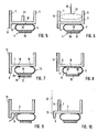
- FIGS. 5 to 10 show various embodiments of the invention connecting profiled strips. As far as possible, the same reference numerals are used to designate the same elements. Basically, the structure of each profile strip is essentially the same. In each case, an outer leg 3 made of hard plastic material is provided, with which a fastening section 4 is coupled in a highly flexible manner via the connecting webs 5. In Fig. 5 the connecting webs 5 are connected in the region of attachment to the outer leg 3 via a connecting portion 24, that is, it forms here a total of a tubular loop 14, which is thus completely closed. This results in a very large-scale connection to the outer leg 3 in a single, very wide connection area 18, unlike the embodiment according to Fig. 1 where two separate connection areas 18 are provided.
- a further central anchoring web 25 is here in addition to the two edge Einputzstegen 6, 7 is provided, which is optional.
- the cover tabs 10 are not shown in this and the following embodiments. These can be provided, but not necessarily.
- the adhesive layer 17 is applied here by way of example directly to the loop 14 or the loop section 15, and no foam tape is arranged therebetween.
- the component mounting portion 4 is not formed by a foam adhesive tape 16 with adhesive layer 17 underneath, but rather a relatively stiff, preferably also made of harder material (corresponding to the material of the outer leg 3, eg hard PVC) on the loop portion 15 Stiffening strip 26 arranged, which can also be formed in a co-extrusion process.
- a stiffer attachment portion 4 as compared to the more elastic attachment portion 4 comprising the soft foam adhesive tape 16.
- an adhesive layer 17 is also applied to the stiffening strip 26, in this case directly.
- a plaster fabric 28 added, which is integrated into the plaster layer for even better anchoring.
- the soft plastic loop 14 is again arranged in two separate attachment areas 18 on the outer leg 3. Again, a stiffening strip 26 is placed on the loop portion 15, but here on a foam adhesive tape 16, which carries the adhesive layer 17, is applied.
- the fairing leg 8 is pulled down a little further because of entire structure below the outer leg 3 is slightly stronger to cover this largely to form the shadow gap.
- a further embodiment of a profiled strip 1 according to the invention Fig. 8 also there, the material loop 14 is arranged from highly flexible soft plastic material in a single, large-scale attachment portion on the outer leg 3.
- the ends of the connecting webs 5 are arranged here in separate attachment regions 29 on a stiffening strip 26, so that no central loop section 15 is formed here as in the previously described embodiments.
- the high relative mobility can also be realized in such an embodiment, since here too, the connecting webs 5 can perform the unrolling or rolling movement according to the invention when a transverse force is introduced due to their geometry and highly flexible design. It would also be conceivable to arrange the two connecting webs 5 in this embodiment also on the outer leg 3 in two separate attachment areas 18.
- Fig. 9 shows a further profile strip, the structure of the profile strip 1 Fig. 1 equivalent.
- a separate sealing lip 9 is provided, which is integrally formed on the underside of the outer leg 3 and ends in the mounting position in the shadow gap 23. As described, such a sealing lip is optional.
- Fig. 10 shows a profiled strip according to the invention, the forth from the basic structure, as far as the design of the movement coupling, etc., in the example shown, the bar off Fig. 1 equivalent.
- the outer Einputzsteg 7 is not disposed on the edge of the outer leg 3, but slightly offset inwards, so that there is a quasi-step shape.
- the fairing web 8 in turn is integrally formed on the outer side edge 3. Both are each provided here with an adhesion-improving coating 13 and can, as shown by way of example, be covered with a plaster layer 22.
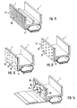
- FIGS. 11-13 show three further embodiments that show various adhesion-improving coverings.
- Fig. 11 shows a profile strip 1, in which it is can be any profile strip of the type described above.
- the adhesion-improving coating 13 here consists of a structured fabric 30, as indicated by the intersecting fabric threads.
- the fabric 30 is made of plastic, but may also be formed from textile fibers. The use of a glass fiber fabric is conceivable.
- the fabric itself has an adhesive surface on which it is glued to the outside of the Einputzsteges 7. It is also conceivable, however, first to apply an adhesive layer to the outside of the outer web 7, to which the fabric is then glued.
- the fabric which may be woven relatively coarse mesh, for example, so that they open structure as possible, in which the plaster layer can dig, also extends over the panel web 8 so that it can be completely plastered.
- the material used to form the fabric 30 may be any, but care must be taken that the material is chemically resistant in that it can not be attacked by any ingredients contained in the plaster layer.
- Fig. 12 shows a profiled strip 1 with an adhesion-improving coating 13 in the form of a glued, structured band 31.
- This band is for example made of plastic and embossed over the surface to form knob-like elevations 32 in the example shown.
- the tape 31 may be self-adhesive, thus having its own adhesive surface, via which it is glued to the outside of the Einputzsteges 7 and the fairing web 8.
- the respective outer side can be provided with an adhesive layer, on which the tape 31 is then glued.
- the knob-like elevations 32 it would of course also be conceivable to form recesses, that is to say to perforate the band 31 so as to structure the surface.
- longitudinal elevations or obliquely running elevations or grooves can be pronounced etc.
- the type of three-dimensional structuring is arbitrary.
- this plastic band for example, a band of PVC, offers the possibility that the plaster layer firmly anchored. It is also conceivable, however, the use of a textile felt or a flocked, so very thin, dense protruding fibers having tape.
- Fig. 13 shows a connection profile strip 1, in which on the outside of the Einputzsteges 7 and the fairing web 8 particles 33 produce the surface structuring.
- the particles 33 are embedded in a carrier medium 34, for example a cured adhesive or a resin layer. This also results in a rough, textured surface to which the plaster adheres over a large area and safely.
- the carrier medium can first be brought to the outside, for example brushed or sprayed on, after which the particles 33, which are, for example, sand or quartz powder, are sprinkled. It is also conceivable, however, to mix these particles into the still viscous carrier medium and then apply the mixture and cure the carrier medium.
- the sand or quartz flour particles it would also be conceivable to apply glass or plastic or wood or metal particles for structuring.
- Fig. 14 finally also shows a profiled strip 1, in which the coating 13 is formed by fibers 36 fixed in a carrier medium 35.
- the fibers 36 may be, for example, plastic or textile fibers.
- the fibers 36 are drawn relatively coarse, so they can also be very fine, so thin and short, so that a total of flocking forms, as in Fig. 14 is additionally shown by the very short fibers 36 '.
- Fig. 15 shows a further embodiment of a bar according to the invention, in which on the outer leg 3 compared to the connecting webs 5 much firmer, more stable connecting webs 37, a component mounting portion 4 forming stiffening strip 26 is provided with the adhered thereto foam adhesive tape 16 with the adhesive layer 17.
- an adhesion-improving coating 13 of any kind is provided on the outer plaster web 7.
- a holding or clamping section 27 piping inserted between the two webs 6, 7, with a plaster fabric 28.
- the various profile bodies 2 shown or configurations of the structure on the outer leg, etc. can be combined with any desired configurations of the fastening section 4 as well as arbitrary configurations of the connecting webs 5 or their connection to the outer leg 3 or to the fastening section 4.
- the various strips can be provided with a lateral Abdecklasche.
- a three-dimensional surface structure can also be formed on the outer web sides themselves.
- the adhesive layer can be applied directly to the loop portion or the fastening portion.
Landscapes
- Engineering & Computer Science (AREA)
- Civil Engineering (AREA)
- Structural Engineering (AREA)
- Laminated Bodies (AREA)
- Bridges Or Land Bridges (AREA)
- Window Of Vehicle (AREA)
Applications Claiming Priority (1)
| Application Number | Priority Date | Filing Date | Title |
|---|---|---|---|
| DE200710023433 DE102007023433B4 (de) | 2007-05-16 | 2007-05-16 | Anschlussprofilleiste, insbesondere Laibungsanschlussprofilleiste |
Publications (2)
| Publication Number | Publication Date |
|---|---|
| EP1992775A2 true EP1992775A2 (fr) | 2008-11-19 |
| EP1992775A3 EP1992775A3 (fr) | 2011-11-09 |
Family
ID=39386429
Family Applications (1)
| Application Number | Title | Priority Date | Filing Date |
|---|---|---|---|
| EP08007999A Withdrawn EP1992775A3 (fr) | 2007-05-16 | 2008-04-25 | Baguette de profilé de raccord, en particulier baguette de profilé de raccord pour le tableau d'une ouverture d'un bâtiment |
Country Status (2)
| Country | Link |
|---|---|
| EP (1) | EP1992775A3 (fr) |
| DE (1) | DE102007023433B4 (fr) |
Cited By (2)
| Publication number | Priority date | Publication date | Assignee | Title |
|---|---|---|---|---|
| EP1992777A3 (fr) * | 2007-05-16 | 2011-11-09 | Roman Zahner | Baguette de profilé de raccord, en particulier baguette de profilé de raccord |
| EP4036347B1 (fr) * | 2021-01-28 | 2024-04-24 | Protektorwerk Florenz Maisch GmbH & Co. KG | Profilé d'enduit avec une feuille d'enduit sur l'un de ses pieds d'enduit |
Families Citing this family (3)
| Publication number | Priority date | Publication date | Assignee | Title |
|---|---|---|---|---|
| DE102014009433A1 (de) * | 2014-06-25 | 2015-12-31 | Jörg Krüger | Anschluss- oder Anputzprofilleiste |
| DE102015121431A1 (de) * | 2015-12-09 | 2017-06-14 | Roman Zahner | Anschlussprofilleiste, insbesondere Laibungsanschlussprofilleiste |
| DE102019125064A1 (de) * | 2019-09-18 | 2021-03-18 | Protektorwerk Florenz Maisch Gmbh & Co. Kg | Profilelement |
Citations (2)
| Publication number | Priority date | Publication date | Assignee | Title |
|---|---|---|---|---|
| US5086598A (en) * | 1989-03-23 | 1992-02-11 | Derrell J. Weldy | Wall board joint reinforcing system |
| US5752353A (en) * | 1996-12-02 | 1998-05-19 | Trim-Tex, Inc. | Drywall-trimming article having curved surface covered with discrete fibers |
Family Cites Families (7)
| Publication number | Priority date | Publication date | Assignee | Title |
|---|---|---|---|---|
| AT6500U1 (de) * | 2002-12-19 | 2003-11-25 | Peter Kassmannhuber | Laibungsanschlussprofil |
| AT6819U1 (de) * | 2003-05-22 | 2004-04-26 | Peter Kassmannhuber | Laibungsanschlussprofil für an putz angrenzende bauteile |
| DE202004012859U1 (de) * | 2004-08-17 | 2004-10-14 | Wörner, Elisabeth | Anschlussprofil |
| DE102005022826B4 (de) * | 2005-05-12 | 2010-04-15 | Roman Zahner | Anschlussprofilleiste, insbesondere Laibungsanschlussprofilleiste |
| DE202005020164U1 (de) * | 2005-12-23 | 2006-03-16 | Vws-Befestigungstechnik Gmbh | Bewegungsausgleichsprofil |
| DE202007001697U1 (de) * | 2007-02-06 | 2007-04-05 | Vws-Befestigungstechnik Gmbh | Anschlussprofil, insbesondere Putzanschlussprofil |
| DE102007023432B4 (de) * | 2007-05-16 | 2012-07-26 | Roman Zahner | Anschlussprofilleiste, insbesondere Laibungsanschlussprofilleiste |
-
2007
- 2007-05-16 DE DE200710023433 patent/DE102007023433B4/de not_active Expired - Fee Related
-
2008
- 2008-04-25 EP EP08007999A patent/EP1992775A3/fr not_active Withdrawn
Patent Citations (2)
| Publication number | Priority date | Publication date | Assignee | Title |
|---|---|---|---|---|
| US5086598A (en) * | 1989-03-23 | 1992-02-11 | Derrell J. Weldy | Wall board joint reinforcing system |
| US5752353A (en) * | 1996-12-02 | 1998-05-19 | Trim-Tex, Inc. | Drywall-trimming article having curved surface covered with discrete fibers |
Cited By (2)
| Publication number | Priority date | Publication date | Assignee | Title |
|---|---|---|---|---|
| EP1992777A3 (fr) * | 2007-05-16 | 2011-11-09 | Roman Zahner | Baguette de profilé de raccord, en particulier baguette de profilé de raccord |
| EP4036347B1 (fr) * | 2021-01-28 | 2024-04-24 | Protektorwerk Florenz Maisch GmbH & Co. KG | Profilé d'enduit avec une feuille d'enduit sur l'un de ses pieds d'enduit |
Also Published As
| Publication number | Publication date |
|---|---|
| DE102007023433A1 (de) | 2008-11-27 |
| EP1992775A3 (fr) | 2011-11-09 |
| DE102007023433B4 (de) | 2012-07-26 |
Similar Documents
| Publication | Publication Date | Title |
|---|---|---|
| EP1992776B1 (fr) | Baguette de profilé de raccord, en particulier baguette de profilé de raccord pour le tableau d'une ouverture d'un bâtiment | |
| EP0530653B1 (fr) | Profilé d'étanchéité | |
| EP2404008B1 (fr) | Dispositif d'étanchéité sur un joint dans une construction | |
| WO2001088303A1 (fr) | Profile | |
| DE102007010997A1 (de) | Fugenband für Sanitäreinrichtungen | |
| DE10228324A1 (de) | Abdichtung über Bewegungsfugen und Verfahren zu deren Herstellung | |
| DE102007023433B4 (de) | Anschlussprofilleiste, insbesondere Laibungsanschlussprofilleiste | |
| DE102007023432B4 (de) | Anschlussprofilleiste, insbesondere Laibungsanschlussprofilleiste | |
| EP3044021A1 (fr) | Élément profilé, en particulier pour un véhicule à moteur, et son procédé de production | |
| DE102005057778A1 (de) | Putzabschlussleiste für eine Putzschicht auf einer Wärmedämmung | |
| EP1627982B1 (fr) | Profilé de jonction | |
| AT521044A4 (de) | Abdeckleiste | |
| EP1956158A2 (fr) | Profil de raccordement, en particulier bande de crépi | |
| DE102005022826B4 (de) | Anschlussprofilleiste, insbesondere Laibungsanschlussprofilleiste | |
| EP1224096B1 (fr) | Procede de fabrication d'une baguette profilee souple | |
| DE102007032081B4 (de) | Anschlussprofilleiste, insbesondere Laibungsanschlussprofilleiste | |
| AT501199B1 (de) | Zweiteiliges laibungsanschlussprofil für an putz angrenzende bauteile | |
| DE102009004690B4 (de) | Anschlussprofilleiste, insbesondere Laibungsanschlussprofilleiste | |
| AT504237A1 (de) | Laibungsanschlussprofil für an putz angrenzende bauteile | |
| DE10321828A1 (de) | Putzprofilleiste zum Abdichten einer Dehnfuge zwischen zwei Gebäudewänden | |
| EP4357551B1 (fr) | Profilé d'enduit | |
| EP2003266A1 (fr) | Profil de raccordement | |
| AT520284A1 (de) | Anputzprofil für den unteren Bereich einer Wandöffnung für Fenster oder Türen, Dämm- und/oder Dichtungsvorrichtung umfassend wenigstens ein solches Anputzprofil und Verfahren zum Einbau einer solchen Dämm- und/oder Dichtungsvorrichtung im unteren Bereich einer Wandöffnung für Fenster oder Türen | |
| DE102010035166A1 (de) | Anschlussprofilleiste, insbesondere Laibungsanschlussprofilleiste | |
| EP2186957A1 (fr) | Garniture de joint et son procédé de fabrication |
Legal Events
| Date | Code | Title | Description |
|---|---|---|---|
| PUAI | Public reference made under article 153(3) epc to a published international application that has entered the european phase |
Free format text: ORIGINAL CODE: 0009012 |
|
| AK | Designated contracting states |
Kind code of ref document: A2 Designated state(s): AT BE BG CH CY CZ DE DK EE ES FI FR GB GR HR HU IE IS IT LI LT LU LV MC MT NL NO PL PT RO SE SI SK TR |
|
| AX | Request for extension of the european patent |
Extension state: AL BA MK RS |
|
| PUAL | Search report despatched |
Free format text: ORIGINAL CODE: 0009013 |
|
| AK | Designated contracting states |
Kind code of ref document: A3 Designated state(s): AT BE BG CH CY CZ DE DK EE ES FI FR GB GR HR HU IE IS IT LI LT LU LV MC MT NL NO PL PT RO SE SI SK TR |
|
| AX | Request for extension of the european patent |
Extension state: AL BA MK RS |
|
| RIC1 | Information provided on ipc code assigned before grant |
Ipc: E06B 1/68 20060101ALI20111006BHEP Ipc: E06B 1/62 20060101AFI20111006BHEP |
|
| 17P | Request for examination filed |
Effective date: 20120118 |
|
| AKX | Designation fees paid |
Designated state(s): AT BE BG CH CY CZ DE DK EE ES FI FR GB GR HR HU IE IS IT LI LT LU LV MC MT NL NO PL PT RO SE SI SK TR |
|
| 17Q | First examination report despatched |
Effective date: 20140313 |
|
| STAA | Information on the status of an ep patent application or granted ep patent |
Free format text: STATUS: THE APPLICATION HAS BEEN WITHDRAWN |
|
| 18W | Application withdrawn |
Effective date: 20140528 |