EP1992810A2 - Gondel mit veränderlicher Geometrie für ein Flugzeugtriebwerk und entsprechendes Betriebsverfahren - Google Patents
Gondel mit veränderlicher Geometrie für ein Flugzeugtriebwerk und entsprechendes Betriebsverfahren Download PDFInfo
- Publication number
- EP1992810A2 EP1992810A2 EP08251743A EP08251743A EP1992810A2 EP 1992810 A2 EP1992810 A2 EP 1992810A2 EP 08251743 A EP08251743 A EP 08251743A EP 08251743 A EP08251743 A EP 08251743A EP 1992810 A2 EP1992810 A2 EP 1992810A2
- Authority
- EP
- European Patent Office
- Prior art keywords
- inlet lip
- lip section
- diameter
- contraction ratio
- recited
- Prior art date
- Legal status (The legal status is an assumption and is not a legal conclusion. Google has not performed a legal analysis and makes no representation as to the accuracy of the status listed.)
- Granted
Links
Images

Classifications
-
- F—MECHANICAL ENGINEERING; LIGHTING; HEATING; WEAPONS; BLASTING
- F02—COMBUSTION ENGINES; HOT-GAS OR COMBUSTION-PRODUCT ENGINE PLANTS
- F02K—JET-PROPULSION PLANTS
- F02K3/00—Plants including a gas turbine driving a compressor or a ducted fan
- F02K3/02—Plants including a gas turbine driving a compressor or a ducted fan in which part of the working fluid by-passes the turbine and combustion chamber
- F02K3/04—Plants including a gas turbine driving a compressor or a ducted fan in which part of the working fluid by-passes the turbine and combustion chamber the plant including ducted fans, i.e. fans with high volume, low pressure outputs, for augmenting the jet thrust, e.g. of double-flow type
- F02K3/06—Plants including a gas turbine driving a compressor or a ducted fan in which part of the working fluid by-passes the turbine and combustion chamber the plant including ducted fans, i.e. fans with high volume, low pressure outputs, for augmenting the jet thrust, e.g. of double-flow type with front fan
-
- F—MECHANICAL ENGINEERING; LIGHTING; HEATING; WEAPONS; BLASTING
- F02—COMBUSTION ENGINES; HOT-GAS OR COMBUSTION-PRODUCT ENGINE PLANTS
- F02C—GAS-TURBINE PLANTS; AIR INTAKES FOR JET-PROPULSION PLANTS; CONTROLLING FUEL SUPPLY IN AIR-BREATHING JET-PROPULSION PLANTS
- F02C7/00—Features, components parts, details or accessories, not provided for in, or of interest apart form groups F02C1/00 - F02C6/00; Air intakes for jet-propulsion plants
- F02C7/04—Air intakes for gas-turbine plants or jet-propulsion plants
- F02C7/042—Air intakes for gas-turbine plants or jet-propulsion plants having variable geometry
-
- F—MECHANICAL ENGINEERING; LIGHTING; HEATING; WEAPONS; BLASTING
- F02—COMBUSTION ENGINES; HOT-GAS OR COMBUSTION-PRODUCT ENGINE PLANTS
- F02C—GAS-TURBINE PLANTS; AIR INTAKES FOR JET-PROPULSION PLANTS; CONTROLLING FUEL SUPPLY IN AIR-BREATHING JET-PROPULSION PLANTS
- F02C7/00—Features, components parts, details or accessories, not provided for in, or of interest apart form groups F02C1/00 - F02C6/00; Air intakes for jet-propulsion plants
- F02C7/04—Air intakes for gas-turbine plants or jet-propulsion plants
- F02C7/057—Control or regulation
-
- F—MECHANICAL ENGINEERING; LIGHTING; HEATING; WEAPONS; BLASTING
- F05—INDEXING SCHEMES RELATING TO ENGINES OR PUMPS IN VARIOUS SUBCLASSES OF CLASSES F01-F04
- F05D—INDEXING SCHEME FOR ASPECTS RELATING TO NON-POSITIVE-DISPLACEMENT MACHINES OR ENGINES, GAS-TURBINES OR JET-PROPULSION PLANTS
- F05D2300/00—Materials; Properties thereof
- F05D2300/50—Intrinsic material properties or characteristics
- F05D2300/505—Shape memory behaviour
-
- Y—GENERAL TAGGING OF NEW TECHNOLOGICAL DEVELOPMENTS; GENERAL TAGGING OF CROSS-SECTIONAL TECHNOLOGIES SPANNING OVER SEVERAL SECTIONS OF THE IPC; TECHNICAL SUBJECTS COVERED BY FORMER USPC CROSS-REFERENCE ART COLLECTIONS [XRACs] AND DIGESTS
- Y02—TECHNOLOGIES OR APPLICATIONS FOR MITIGATION OR ADAPTATION AGAINST CLIMATE CHANGE
- Y02T—CLIMATE CHANGE MITIGATION TECHNOLOGIES RELATED TO TRANSPORTATION
- Y02T50/00—Aeronautics or air transport
- Y02T50/60—Efficient propulsion technologies, e.g. for aircraft
Definitions
- This invention generally relates to a gas turbine engine, and more particularly to a nacelle assembly for a gas turbine engine.
- air is pressurized in a compressor and mixed with fuel in a combustor for generating hot combustion gases.
- the hot combustion gases flow downstream through turbine stages which extract energy from the hot combustion gases.
- a fan supplies air to the compressor.
- Combustion gases are discharged from the turbofan engine through a core exhaust nozzle and a quantity of fan air is discharged through an annular fan exhaust nozzle defined at least partially by a nacelle assembly surrounding the core engine.
- a majority of propulsion thrust is provided by the pressurized fan air which is discharged through the fan exhaust nozzle, while the remaining thrust is provided from the combustion gases discharged through the core exhaust nozzle.
- An inlet lip section located at the foremost end of the turbofan nacelle assembly is typically designed to enable operation of the turbofan engine and reduce separation of airflow from the internal surfaces of the inlet lip section during these diversified conditions.
- the inlet lip section requires a "thick" inlet lip section to support operation of the engine during specific flight conditions, such as crosswind conditions, take-off conditions and the like.
- the "thick" inlet lip section may reduce the efficiency of the turbofan engine during normal cruise conditions of the aircraft, for example.
- the maximum diameter of the nacelle assembly is approximately 10-20% larger than required during cruise conditions.
- Nacelle assemblies having a variable air inlet which alter the shape of the inlet lip section during take-off and landing conditions to reduce the drag experienced by the aircraft.
- Variable air inlets of this type include a plurality of actuating mechanisms that effectuate the shape change of the inlet lip section.
- the actuating mechanisms are mechanically complex, difficult to incorporate into the nacelle assembly, and provide negative weight penalties. Additionally, these systems have not fully reduced the drag penalties and flow separation problems that occur during aircraft operation.
- a nacelle assembly in one aspect, includes an inlet lip section having a highlight diameter and a throat diameter. One of the highlight diameter and the throat diameter is fixed and the other of the highlight diameter and the throat diameter is selectively adjustable in each of a first direction and a second direction relative to the inlet lip section to influence a contraction ratio associated with the inlet lip section.
- a structural assembly for a gas turbine engine in another aspect, includes a nacelle assembly having an inlet lip section positioned adjacent a forward segment of the nacelle assembly.
- the inlet lip section includes a mechanism having an adjustable shape. The mechanism is selectively moveable to alter the adjustable shape and influence a contraction ratio of the inlet lip section.
- a method of adjusting a contraction ratio associated with an inlet lip section of a gas turbine engine includes detecting an operability condition, and adjusting the inlet lip section in each of an axial direction and a radial direction relative to one of a highlight diameter and a throat diameter in response to the detected operability condition.
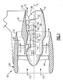
- Figure 1 illustrates a gas turbine engine 10 which includes (in serial flow communication) a fan section 14, a low pressure compressor 15, a high pressure compressor 16, a combustor 18, a high pressure turbine 20, and a low pressure turbine 22.
- air is pulled into the gas turbine engine 10 by the fan section 14, pressurized by the compressors 15, 16 and is mixed with fuel and burned in the combustor 18.
- Hot combustion gases generated within the combustor 18 flow through the high and low pressure turbines 20, 22 which extract energy from the hot combustion gases.
- the high pressure turbine 20 utilizes the extracted energy from the hot combustion gases to power the high pressure compressor 16 through a high speed shaft 19
- a low pressure turbine 22 utilizes the energy extracted from the hot combustion gases to power the low pressure compressor 15 and the fan section 14 through a low speed shaft 21.
- the invention is not limited to the two spool gas turbine architecture described and may be used with other architecture such as a single spool axial design, a three spool axial design and other architectures. That is, the present invention is applicable to any gas turbine engine, and to any application.
- the example gas turbine engine 10 is in the form of a high bypass ratio turbofan engine mounted within a nacelle assembly 26, in which a significant amount of air pressurized by the fan section 14 bypasses the core engine 39 for the generation of propulsion thrust.
- the nacelle assembly 26 partially surrounds an engine casing 31, which houses the core engine 39.
- the airflow entering the fan section 14 may bypass the core engine 39 via a fan bypass passage 30 that extends between the nacelle assembly 26 and the engine casing 31 for receiving and communicating a discharge airflow F1.
- the high bypass flow arrangement provides a significant amount of thrust for powering an aircraft.
- the engine 10 may include a gear train 23 which reduces the speed of the rotating fan section 14.
- the gear train 23 can be any known gear system, such as a planetary gear system with orbiting planet gears, a planetary gear system with non-orbiting planet gears, or other type of gear system.
- the gear train 23 has a constant gear ratio. It should be understood, however, that the above-parameters are only exemplary of a contemplated geared turbofan engine 10. That is, the invention is applicable to traditional turbofan engines as well as other engine architectures.
- the discharge airflow F1 is discharged from the engine 10 through a fan exhaust nozzle 33.
- Core exhaust gases C are discharged from the core engine 39 through a core exhaust nozzle 32 positioned between the engine casing 31 and a center plug 34 disposed coaxially about a longitudinal centerline axis A of the gas turbine engine 10.
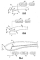
- Figure 2 illustrates an example inlet lip section 38 of the nacelle assembly 26.
- the inlet lip section 38 is positioned near a forward segment 29 of the nacelle assembly 26.
- a boundary layer 35 is associated with the inlet lip section 38.
- the boundary layer 35 represents an area adjacent to a flow surface of the inlet lip section 38 at which the velocity gradient of airflow is zero. That is, the velocity profile of oncoming airflow F2 goes from a free stream away from the boundary layer 35 to near zero at the boundary layer 35 due to the friction forces that occur as the oncoming airflow F2 passes over the outer flow surface of the inlet lip section 38.
- the nacelle assembly 26 also defines a contraction ratio.
- the contraction ratio represents a relative thickness of the inlet lip section 38 of the nacelle assembly 26 and is represented by the ratio of a highlight area H a (ring shaped area defined by a highlight diameter D h ) and a throat area T a (ring shaped area defined by throat diameter D t ) of the nacelle assembly 26.
- Current design considerations typically require a contraction ratio of approximately 1.33 to accommodate each operability condition of the aircraft and prevent the separation of the oncoming airflow F2 from the inlet lip section 38 during engine operation and limit the amount of drag experienced by the aircraft during flight.
- "Thick" inlet lip section designs which are associated with large contraction ratios, increase the maximum diameter D max and increase weight and drag penalties associated with the nacelle assembly 26 during certain operability conditions.
- Adjusting the contraction ratio associated with the inlet lip section 38 during each specific flight condition experienced by the aircraft reduces the boundary layer separation and drag penalties that occur at specific flight conditions.
- the adjustable contraction ratio is achieved by providing an inlet lip section 38 having a variable geometry, as is further discussed below.
- Figure 3 illustrates an example lip section 38 having an adjustable contraction ratio.
- the contraction ratio of the inlet lip section 38 is adjusted by translating a portion of the inlet lip section 38 in response to detecting an operability condition.
- a sensor 61 detects the operability condition and communicates with a controller 62 to translate the inlet lip section 38 in a radial direction X and an axial direction Y relative to the nacelle assembly 26.
- this view is highly schematic.
- the illustrations of the movement of the inlet lip section 38 in the directions X and Y are shown exaggerated to better illustrate the contraction ratio adjustment of the inlet lip section 38.
- a person of ordinary skill in the art would understand the distances the inlet lip section 38 should be displaced in each of the X and Y directions in response to sensing each specific operability condition.
- the sensors 61 and the controller 62 may be programmable to detect any known operability condition of the aircraft and that each operability condition will be associated with a distinct contraction ratio. That is, the sensors 61 and the controller 62 are operable to position the inlet lip section 38 at an appropriate contraction ratio that corresponds to the operability condition that is detected (i.e., the contraction ratio is controlled via a predetermined schedule programmed within the controller 62). Also, the sensor 61 can be replaced by any controller associated with the gas turbine engine 10 or an associated aircraft. In fact, the controller 62 itself can generate the signal to adjust the contraction ratio of the inlet lip section 38.
- the highlight diameter D h of the inlet lip section 38 is fixed and the throat diameter D t is adjusted in the radial direction X and the axial direction Y to alter the contraction ratio of the inlet lip section 38.
- the throat diameter D t of the inlet lip section 38 is translated in a radial inward and axially downstream direction where a "thin" inlet lip section 38 is required, such as during cruise conditions, for example (Labeled position A in Figure 3 ).
- the throat diameter D t is moved in a radially outward direction and an axially upstream direction in response to detecting operability conditions requiring a "thick" inlet lip section 38 (labeled as position A' in Figure 3 ). It should be understood that the actual distances the inlet lip section 38 is translated in the radial and axial directions will vary depending upon design specific parameters including but not limited to the operability conditions experienced by the aircraft.
- the throat diameter D t of the inlet lip section 38 is fixed and the highlight diameter D h of the inlet lip section 38 is varied to adjust the contraction ratio of the inlet lip section 38.
- the highlight diameter D h is translated in a radially inward direction and an axially downstream direction where a "thin" inlet lip section 38 is required, such as during cruise conditions, for example (Labeled as position B in Figure 4 ).
- the highlight diameter D h is moved in a radial outward direction and an axially upstream direction where a "thick" inlet lip section 38 is required (Labeled as position B' in Figure 4 ).
- Figures 3 and 4 illustrate the contraction ratio adjustment relative to a single position of the highlight diameter D h or the throat diameter D t , it should be understood that the movement could occur around the entire circumference of the nacelle assembly 26 to adjust the contraction ratio associated with the inlet lip section 38.
- the contraction ratio of the inlet lip section 38 is selectively adjustable between a range of about 1 to about 1.4 and depends upon the detected operability condition.
- the term "about” as used in this description relative to the contraction ratio refers to possible variations in the contraction ratio, such as normally acceptable variations and tolerances in the art.
- a person of ordinary skill in the art would understand how to program the controller 62 of the gas turbine engine 10 to associate a distinct contraction ratio between the range of about 1 to about 1.4 for each operability condition the gas turbine engine 10 may experience during operation.
- the ratio of the maximum diameter Dmax relative to the highlight diameter D h is less than or equal to about 1.5, for example.
- a person of ordinary skill in the art would understand that other ratios of the maximum diameter Dmax relative to the highlight diameter D h are possible and will vary depending upon design specific parameters.
- the contraction ratio of the inlet lip section 38 is selectively adjusted in response to detecting an operability condition.
- the operability condition includes a take-off condition.
- the operability condition includes a climb condition.
- the operability condition includes a crosswind condition. Crosswind conditions are experienced during takeoff as an aircraft travels down a runway (i.e., where the aircraft experiences airflow in a roughly perpendicular direction with respect to the movement of aircraft down the runway).
- the operability condition includes a windmilling condition. A windmilling condition occurs where an engine of a multi-engine aircraft loses functionality or is otherwise shutdown (i.e., an engine out condition).
- the damaged engine is advantageously permitted to rotate, and is driven by an airflow resulting from the forward velocity of the aircraft (i.e., the damaged engine is permitted to windmill).
- the operability condition includes cruise conditions of the aircraft. It should be understood that the contraction ratio of the inlet lip section 38 may be adjusted in a radial direction X and an axial direction Y, or to any position, in response to a detected operability condition.
- FIG. 5 illustrates an example internal linkage 56 utilized to adjust the contraction ratio associated with the inlet lip section 38.
- the internal linkage 56 is housed within a cavity 78 of the inlet lip section 38.
- An actuator assembly 80 deploys the internal linkage 56 by pivoting, toggling, and/or extending the internal linkage 56 to move one of the throat diameter D t or the highlight diameter D h in a radial direction X and/or an axial direction Y.
- a person of ordinary skill in the art having the benefit of this disclosure would be able to implement an appropriate actuator assembly 80 to translate the internal linkage 56.
- the example actuator assembly 80 could include a pneumatic, hydraulic, electromagnetic or any other type of actuator assembly.
- the inlet lip section 38 of the nacelle assembly 26 includes an outer skin comprised of a flexible material that is adjustable to achieve the contraction ratio adjustment. A person of ordinary skill in the art having the benefit of this disclosure would be able to choose an appropriate material for the flexible outer skin.
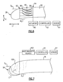
- Figure 6 illustrates a second example mechanism for adjusting the contraction ratio of the inlet lip section 38.
- the inlet lip section 38 includes a plurality of bellows 90 positioned between a front bulk head 92 and a maximum thickness point 94 of the inlet lip section 38.
- the bellows 90 extend circumferentially about the entire nacelle assembly 26, although only a single position of the bellows 90 is illustrated in Figure 6 .
- Each bellow 90 includes a first hinge 96 positioned adjacent to the front bulk head 92 and a second hinge 98 positioned adjacent to the maximum thickness point 94 of the inlet lip section 38.
- Each bellow 90 is translatable in each of a radial direction and an axial direction with respect to either the highlight diameter D h or the throat diameter D t of inlet lip section 38 by moving the hinges 96, 98 either toward or away from one another (i.e., in either an upstream direction or downstream direction relative to one another). That is, one of the highlight diameter D h and the throat diameter D t is fixed.
- An actuator assembly 80 is associated with the bellows 90 to translate the bellows 90 in response to receiving a signal from the controller 62 representing a detected operability condition.
- the bellows 90 of the nacelle assembly 26 include an outer skin comprised of a flexible material. A person of ordinary skill in the art having the benefit of this disclosure would be able to choose an appropriate material for the flexible outer skin.
- Figure 7 illustrates yet another example mechanism for adjusting the contraction ratio associated with the inlet lip section 38.
- the inlet lip section 38 comprises a shape memory alloy 100 having a first solid phase that corresponds to a first shape of the inlet lip section 38 and a second solid phase that corresponds to a second shape of inlet lip section 38.
- the inlet lip section 38 may be transitioned between the first solid phase and the second solid phase to adjust the contraction ratio of the inlet lip section 38.
- the second solid phase is radially inward and downstream relative to the first solid phase (labeled as position C in Figure 7 ).
- the second solid phase is radially outward and upstream relative to the first solid phase (labeled as position C' in Figure 7 ).
- the shape memory alloy is thermally or magnetically active to transition the shape memory alloy between the phases to change the shape of the inlet lip section 38 with respect to one of the highlight diameter D h and the throat diameter D t .
- the entire inlet lip section 38 includes a shape memory alloy. In another example, only the areas adjacent to either the highlight diameter D h or the throat diameter D t include a shape memory alloy.
- One example thermally active shape memory alloy includes a nickel titanium alloy.
- a second example thermally active shape memory alloy includes a copper zinc aluminum alloy.
- Yet another example thermally active shape memory alloy includes a copper aluminum nickel alloy.
- One example mechanically active shape memory alloy includes a nickel manganese gallium alloy.
- other shape memory alloys may be utilized, as would be understood by those of ordinary skill in the art having the benefit of this disclosure.
- the shape memory alloy provides the adjustment of the contraction ratio of the inlet lip section 38.
- the inlet lip section 38 of the nacelle assembly 26 includes an outer skin comprised of a flexible material. A person of ordinary skill in the art having the benefit of this disclosure would be able to choose an appropriate material for the flexible outer skin.
- Adjusting the contracting ratio of the inlet lip section 38 during specific flight conditions accommodates competing design considerations of an aircraft by providing a "thick" inlet lip section 38 or a “thin” inlet lip section 38 as required by specific operating conditions.
- the drag experienced by the aircraft caused by the airflow communicated through the inlet lip section and the nacelle assembly is reduced. Therefore, efficiency is improved during all operability conditions of the gas turbine engine 10.
- the inlet lip section 38 operates with reduced flow separation and increased inlet pressure recovery during all flight conditions. A reduced maximum diameter of the nacelle assembly 26 may therefore be achieved while reducing weight, reducing fuel burn and increasing the overall efficiency of the gas turbine engine 10.
Landscapes
- Engineering & Computer Science (AREA)
- Chemical & Material Sciences (AREA)
- Combustion & Propulsion (AREA)
- Mechanical Engineering (AREA)
- General Engineering & Computer Science (AREA)
- Physics & Mathematics (AREA)
- Geometry (AREA)
- Control Of Turbines (AREA)
Applications Claiming Priority (1)
| Application Number | Priority Date | Filing Date | Title |
|---|---|---|---|
| US11/750,398 US8727267B2 (en) | 2007-05-18 | 2007-05-18 | Variable contraction ratio nacelle assembly for a gas turbine engine |
Publications (3)
| Publication Number | Publication Date |
|---|---|
| EP1992810A2 true EP1992810A2 (de) | 2008-11-19 |
| EP1992810A3 EP1992810A3 (de) | 2013-04-24 |
| EP1992810B1 EP1992810B1 (de) | 2014-05-28 |
Family
ID=39719228
Family Applications (1)
| Application Number | Title | Priority Date | Filing Date |
|---|---|---|---|
| EP08251743.4A Active EP1992810B1 (de) | 2007-05-18 | 2008-05-19 | Gondel mit veränderlicher Geometrie für ein Flugzeugtriebwerk und entsprechendes Betriebsverfahren |
Country Status (2)
| Country | Link |
|---|---|
| US (1) | US8727267B2 (de) |
| EP (1) | EP1992810B1 (de) |
Cited By (4)
| Publication number | Priority date | Publication date | Assignee | Title |
|---|---|---|---|---|
| EP2864619B1 (de) | 2012-06-22 | 2018-08-15 | United Technologies Corporation | Steuerung einer vorrichtung zur strömungsstabilitätsverbesserung für eine turbomaschine |
| EP3438000A1 (de) * | 2017-08-01 | 2019-02-06 | Safran Aircraft Engines | Aktives system, das destruktive akustische interferenzen für einen luftfahrzeugmotor mit mehreren gebläsekörpern erzeugt |
| FR3094957A1 (fr) * | 2019-04-10 | 2020-10-16 | Safran | Systeme propulsif pour un aeronef |
| WO2020212225A1 (fr) | 2019-04-17 | 2020-10-22 | Safran Aircraft Engines | Procédé d'utilisation d'une entrée d'air de nacelle de turboréacteur comprenant une lèvre d'entrée d'air comprenant une portion mobile pour favoriser une phase d'inversion de poussée |
Families Citing this family (37)
| Publication number | Priority date | Publication date | Assignee | Title |
|---|---|---|---|---|
| US20050274103A1 (en) * | 2004-06-10 | 2005-12-15 | United Technologies Corporation | Gas turbine engine inlet with noise reduction features |
| US7797944B2 (en) | 2006-10-20 | 2010-09-21 | United Technologies Corporation | Gas turbine engine having slim-line nacelle |
| US7870721B2 (en) * | 2006-11-10 | 2011-01-18 | United Technologies Corporation | Gas turbine engine providing simulated boundary layer thickness increase |
| US8408491B2 (en) * | 2007-04-24 | 2013-04-02 | United Technologies Corporation | Nacelle assembly having inlet airfoil for a gas turbine engine |
| US8205430B2 (en) * | 2007-05-16 | 2012-06-26 | United Technologies Corporation | Variable geometry nacelle assembly for a gas turbine engine |
| US20080310956A1 (en) * | 2007-06-13 | 2008-12-18 | Jain Ashok K | Variable geometry gas turbine engine nacelle assembly with nanoelectromechanical system |
| US8402739B2 (en) | 2007-06-28 | 2013-03-26 | United Technologies Corporation | Variable shape inlet section for a nacelle assembly of a gas turbine engine |
| US9004399B2 (en) | 2007-11-13 | 2015-04-14 | United Technologies Corporation | Nacelle flow assembly |
| US8186942B2 (en) | 2007-12-14 | 2012-05-29 | United Technologies Corporation | Nacelle assembly with turbulators |
| US8192147B2 (en) | 2007-12-14 | 2012-06-05 | United Technologies Corporation | Nacelle assembly having inlet bleed |
| GB0813482D0 (en) | 2008-07-24 | 2008-08-27 | Rolls Royce Plc | Gas turbine engine nacelle |
| GB0813484D0 (en) * | 2008-07-24 | 2008-08-27 | Rolls Royce Plc | Gas turbine engine nacelle |
| US20110147533A1 (en) * | 2009-12-21 | 2011-06-23 | Honeywell International Inc. | Morphing ducted fan for vertical take-off and landing vehicle |
| US20140182309A1 (en) * | 2012-12-28 | 2014-07-03 | United Technologies Corporation | Geared gas turbine engine exhaust nozzle with chevrons |
| US11480104B2 (en) | 2013-03-04 | 2022-10-25 | Raytheon Technologies Corporation | Gas turbine engine inlet |
| WO2014143248A1 (en) * | 2013-03-15 | 2014-09-18 | KARAM, Michael | Ultra high bypass ratio turbofan engine |
| US9869190B2 (en) | 2014-05-30 | 2018-01-16 | General Electric Company | Variable-pitch rotor with remote counterweights |
| US10072510B2 (en) | 2014-11-21 | 2018-09-11 | General Electric Company | Variable pitch fan for gas turbine engine and method of assembling the same |
| US10100653B2 (en) | 2015-10-08 | 2018-10-16 | General Electric Company | Variable pitch fan blade retention system |
| US10399687B2 (en) | 2015-12-03 | 2019-09-03 | The Boeing Company | Methods and apparatus to vary an air intake of aircraft engines |
| US10738699B2 (en) | 2018-01-19 | 2020-08-11 | Rolls-Royce North American Technologies Inc. | Air-inlet particle separator having a bleed surface |
| GB202007010D0 (en) | 2020-05-13 | 2020-06-24 | Rolls Royce Plc | Nacelle for gas turbine engine |
| US11629651B2 (en) * | 2020-11-17 | 2023-04-18 | General Electric Company | Gas turbine engine having a turbomachine and an electric motor coupled to a propeller |
| CN112623237B (zh) * | 2020-12-31 | 2022-08-30 | 厦门大学 | 基于形状记忆合金的tbcc进气道调节机构设计方法 |
| US11674435B2 (en) | 2021-06-29 | 2023-06-13 | General Electric Company | Levered counterweight feathering system |
| US11795964B2 (en) | 2021-07-16 | 2023-10-24 | General Electric Company | Levered counterweight feathering system |
| US12601271B2 (en) | 2022-10-21 | 2026-04-14 | General Electric Company | Variable pitch fan of a gas turbine engine |
| US12428962B1 (en) | 2024-06-14 | 2025-09-30 | General Electric Company | Gas turbine engine with acoustic spacing of the fan blades and outlet guide vanes |
| US12421854B1 (en) * | 2024-06-14 | 2025-09-23 | General Electric Company | Gas turbine engine with acoustic spacing of the fan blades and outlet guide vanes |
| US12497923B1 (en) | 2024-06-14 | 2025-12-16 | General Electric Company | Gas turbine engine with acoustic spacing of the fan blades and outlet guide vanes |
| US12292017B1 (en) * | 2024-06-14 | 2025-05-06 | General Electric Company | Gas turbine engine with acoustic spacing of the fan blades and outlet guide vanes |
| US12560125B2 (en) | 2024-06-14 | 2026-02-24 | General Electric Company | Gas turbine engine with acoustic spacing of the fan blades and outlet guide vanes |
| US12510104B2 (en) | 2024-06-14 | 2025-12-30 | General Electric Company | Gas turbine engine with acoustic spacing of the fan blades and outlet guide vanes |
| US12429067B1 (en) | 2024-06-14 | 2025-09-30 | General Electric Company | Gas turbine engine with acoustic spacing of the fan blades and outlet guide vanes |
| US12529335B1 (en) * | 2024-10-09 | 2026-01-20 | General Electric Company | Turbine engine having a variable engine intake system |
| US12442333B1 (en) | 2024-10-09 | 2025-10-14 | General Electric Company | Turbine engine having a variable engine intake system |
| US12435666B1 (en) * | 2024-10-09 | 2025-10-07 | General Electric Company | Turbine engine having a variable engine intake system |
Citations (4)
| Publication number | Priority date | Publication date | Assignee | Title |
|---|---|---|---|---|
| GB800380A (en) | 1955-05-09 | 1958-08-27 | Plessey Co Ltd | Improvements in or relating to intakes for air inspiring apparatus |
| GB1067129A (en) | 1966-03-15 | 1967-05-03 | Rolls Royce | Improvements relating to the silencing of gas turbine engines |
| US6089505A (en) | 1997-07-22 | 2000-07-18 | Mcdonnell Douglas Corporation | Mission adaptive inlet |
| EP1607603A2 (de) | 2004-06-10 | 2005-12-21 | United Technologies Corporation | Gasturbinentriebwerkeinlass mit Lärmreduktionsmerkmal |
Family Cites Families (66)
| Publication number | Priority date | Publication date | Assignee | Title |
|---|---|---|---|---|
| US2948111A (en) * | 1955-05-02 | 1960-08-09 | Doak Aircraft Co Inc | Means to increase static pressure and enhance forward thrust of aircraft components |
| US3222863A (en) * | 1963-10-07 | 1965-12-14 | Boeing Co | Aerodynamic inlet |
| GB1070458A (en) | 1964-06-12 | 1967-06-01 | Boeing Co | Separator for removing foreign matter from a gas stream |
| US3568694A (en) * | 1968-05-08 | 1971-03-09 | Lockheed Aircraft Corp | Jet engine installation for noise control |
| GB1312619A (en) | 1969-10-03 | 1973-04-04 | Secr Defence | Air intakes for gas turbine engines |
| US3583417A (en) * | 1969-10-07 | 1971-06-08 | Boeing Co | Sound suppressor for jet engine inlet |
| US3664612A (en) * | 1969-12-22 | 1972-05-23 | Boeing Co | Aircraft engine variable highlight inlet |
| US3611724A (en) * | 1970-01-07 | 1971-10-12 | Gen Electric | Choked inlet noise suppression device for a turbofan engine |
| US3716209A (en) * | 1970-06-01 | 1973-02-13 | Mini Of Technology | Fluid dynamic lift generating or control force generating structures |
| GB1336724A (en) | 1970-11-03 | 1973-11-07 | Secr Defence | Gas turbine engine air intakes |
| GB1382809A (en) | 1971-12-04 | 1975-02-05 | Rolls Royce | Air intakes for gas turbine engines |
| US4007891A (en) * | 1975-09-12 | 1977-02-15 | The United States Of America As Represented By The Administrator Of The National Aeronautics And Space Administration | Jet engine air intake system |
| US4044973A (en) * | 1975-12-29 | 1977-08-30 | The Boeing Company | Nacelle assembly and mounting structures for a turbofan jet propulsion engine |
| US4147029A (en) * | 1976-01-02 | 1979-04-03 | General Electric Company | Long duct mixed flow gas turbine engine |
| US4083181A (en) * | 1976-06-14 | 1978-04-11 | The United States Of America As Represented By The Administrator Of The National Aeronautics And Space Administration | Gas turbine engine with recirculating bleed |
| FR2370171A1 (fr) * | 1976-11-05 | 1978-06-02 | Snecma | Procede et dispositif pour la diminution du bruit des turbomachines |
| US4351502A (en) * | 1980-05-21 | 1982-09-28 | The Boeing Company | Continuous skin, variable camber airfoil edge actuating mechanism |
| US4475702A (en) * | 1982-12-28 | 1984-10-09 | The Boeing Company | Variable camber leading edge assembly for an airfoil |
| US4540143A (en) * | 1983-08-04 | 1985-09-10 | The Boeing Company | Nacelle/wing assembly with wake control device |
| US4722357A (en) * | 1986-04-11 | 1988-02-02 | United Technologies Corporation | Gas turbine engine nacelle |
| GB8630754D0 (en) * | 1986-12-23 | 1987-02-04 | Rolls Royce Plc | Turbofan gas turbine engine |
| DE3720318A1 (de) * | 1987-06-19 | 1989-01-05 | Mtu Muenchen Gmbh | Gondel fuer strahltriebwerke |
| US4912921A (en) * | 1988-03-14 | 1990-04-03 | Sundstrand Corporation | Low speed spool emergency power extraction system |
| US4899958A (en) * | 1988-12-05 | 1990-02-13 | Mitsubishi Jukogyo Kabushiki Kaisha | Air intake system of an aircraft |
| US5127222A (en) * | 1989-01-23 | 1992-07-07 | United Technologies Corporation | Buffer region for the nacelle of a gas turbine engine |
| US5012639A (en) * | 1989-01-23 | 1991-05-07 | United Technologies Corporation | Buffer region for the nacelle of a gas turbine engine |
| US5014933A (en) * | 1989-04-27 | 1991-05-14 | The Boeing Company | Translating lip aircraft cowling structure adapted for noise reduction |
| US4993663A (en) * | 1989-06-01 | 1991-02-19 | General Electric Company | Hybrid laminar flow nacelle |
| US5000399A (en) * | 1990-02-23 | 1991-03-19 | General Electric Company | Variable contour annular air inlet for an aircraft engine nacelle |
| DE4009223A1 (de) * | 1990-03-22 | 1991-09-26 | Mtu Muenchen Gmbh | Propfan-turbotriebwerk |
| US5143329A (en) * | 1990-06-01 | 1992-09-01 | General Electric Company | Gas turbine engine powered aircraft environmental control system and boundary layer bleed |
| US5058617A (en) * | 1990-07-23 | 1991-10-22 | General Electric Company | Nacelle inlet for an aircraft gas turbine engine |
| GB9025023D0 (en) * | 1990-11-16 | 1991-01-02 | Rolls Royce Plc | Engine nacelle |
| US5284012A (en) * | 1991-05-16 | 1994-02-08 | General Electric Company | Nacelle cooling and ventilation system |
| US5297765A (en) * | 1992-11-02 | 1994-03-29 | Rohr, Inc. | Turbine engine nacelle laminar flow control arrangement |
| US5261227A (en) * | 1992-11-24 | 1993-11-16 | General Electric Company | Variable specific thrust turbofan engine |
| US5361828A (en) * | 1993-02-17 | 1994-11-08 | General Electric Company | Scaled heat transfer surface with protruding ramp surface turbulators |
| US5447283A (en) * | 1994-02-02 | 1995-09-05 | Grumman Aerospace Corporation | Blown boundary layer control system for a jet aircraft |
| DE4426351B4 (de) * | 1994-07-25 | 2006-04-06 | Alstom | Brennkammer für eine Gasturbine |
| GB9424495D0 (en) * | 1994-12-05 | 1995-01-25 | Short Brothers Plc | Aerodynamic low drag structure |
| US5586431A (en) * | 1994-12-06 | 1996-12-24 | United Technologies Corporation | Aircraft nacelle ventilation and engine exhaust nozzle cooling |
| US5593112A (en) * | 1994-12-06 | 1997-01-14 | United Technologies Corporation | Nacelle air pump for vector nozzles for aircraft |
| US5987880A (en) * | 1997-07-08 | 1999-11-23 | Mcdonnell Douglas Corporation | Supersonic engine, multi-port thrust reversing system |
| US6129311A (en) * | 1997-07-30 | 2000-10-10 | The Boeing Company | Engine nacelle outer cowl panel with integral track fairings |
| US5971328A (en) * | 1998-01-15 | 1999-10-26 | Kota; Sridhar | System for varying a surface contour |
| US6179251B1 (en) * | 1998-02-06 | 2001-01-30 | Northrop Grumman Corporation | Thin inlet lip design for low drag and reduced nacelle size |
| US6390418B1 (en) * | 1999-02-25 | 2002-05-21 | United Technologies Corporation | Tangentially directed acoustic jet controlling boundary layer |
| US6379110B1 (en) * | 1999-02-25 | 2002-04-30 | United Technologies Corporation | Passively driven acoustic jet controlling boundary layers |
| US6109566A (en) * | 1999-02-25 | 2000-08-29 | United Technologies Corporation | Vibration-driven acoustic jet controlling boundary layer separation |
| GB9921935D0 (en) * | 1999-09-17 | 1999-11-17 | Rolls Royce | A nacelle assembly for a gas turbine engine |
| US6340135B1 (en) * | 2000-05-30 | 2002-01-22 | Rohr, Inc. | Translating independently mounted air inlet system for aircraft turbofan jet engine |
| US6334753B1 (en) * | 2000-07-31 | 2002-01-01 | United Technologies Corporation | Streamlined bodies with counter-flow fluid injection |
| US7048229B2 (en) * | 2000-09-26 | 2006-05-23 | Techland Research, Inc. | Low sonic boom inlet for supersonic aircraft |
| DE10059212A1 (de) * | 2000-11-29 | 2002-06-13 | Grohe Armaturen Friedrich | Brausehaltevorrichtung |
| US6651929B2 (en) | 2001-10-29 | 2003-11-25 | Pratt & Whitney Canada Corp. | Passive cooling system for auxiliary power unit installation |
| FR2831922B1 (fr) * | 2001-11-02 | 2004-04-30 | Airbus France | Entree d'air pour nacelle de moteur a reaction d'avion commercial |
| DE10330023A1 (de) * | 2002-07-20 | 2004-02-05 | Alstom (Switzerland) Ltd. | Wirbelgenerator mit kontrollierter Nachlaufströmung |
| US6655632B1 (en) * | 2002-08-27 | 2003-12-02 | General Electric Company | System and method for actively changing an effective flow-through area of an inlet region of an aircraft engine |
| US6764043B2 (en) * | 2002-12-11 | 2004-07-20 | The Boeing Company | Rotatable scarf inlet for an aircraft engine and method of using the same |
| US6971229B2 (en) * | 2003-02-26 | 2005-12-06 | The Nordam Group, Inc. | Confluent exhaust nozzle |
| BRPI0408101A (pt) * | 2003-03-03 | 2006-05-23 | Flexsys Inc | asa complacente adaptável e sistema de rotor |
| US7090165B2 (en) * | 2003-06-02 | 2006-08-15 | Rolls-Royce Plc | Aeroengine nacelle |
| US7131612B2 (en) * | 2003-07-29 | 2006-11-07 | Pratt & Whitney Canada Corp. | Nacelle inlet lip anti-icing with engine oil |
| GB0401189D0 (en) * | 2004-01-21 | 2004-02-25 | Rolls Royce Plc | Turbine engine arrangements |
| GB0505246D0 (en) * | 2005-03-15 | 2005-04-20 | Rolls Royce Plc | Engine noise |
| US7617670B2 (en) * | 2006-03-31 | 2009-11-17 | Lockheed Martin Corporation | Flow control redistribution to mitigate high cycle fatigue |
-
2007
- 2007-05-18 US US11/750,398 patent/US8727267B2/en not_active Expired - Fee Related
-
2008
- 2008-05-19 EP EP08251743.4A patent/EP1992810B1/de active Active
Patent Citations (4)
| Publication number | Priority date | Publication date | Assignee | Title |
|---|---|---|---|---|
| GB800380A (en) | 1955-05-09 | 1958-08-27 | Plessey Co Ltd | Improvements in or relating to intakes for air inspiring apparatus |
| GB1067129A (en) | 1966-03-15 | 1967-05-03 | Rolls Royce | Improvements relating to the silencing of gas turbine engines |
| US6089505A (en) | 1997-07-22 | 2000-07-18 | Mcdonnell Douglas Corporation | Mission adaptive inlet |
| EP1607603A2 (de) | 2004-06-10 | 2005-12-21 | United Technologies Corporation | Gasturbinentriebwerkeinlass mit Lärmreduktionsmerkmal |
Cited By (9)
| Publication number | Priority date | Publication date | Assignee | Title |
|---|---|---|---|---|
| EP2864619B1 (de) | 2012-06-22 | 2018-08-15 | United Technologies Corporation | Steuerung einer vorrichtung zur strömungsstabilitätsverbesserung für eine turbomaschine |
| EP3438000A1 (de) * | 2017-08-01 | 2019-02-06 | Safran Aircraft Engines | Aktives system, das destruktive akustische interferenzen für einen luftfahrzeugmotor mit mehreren gebläsekörpern erzeugt |
| FR3069850A1 (fr) * | 2017-08-01 | 2019-02-08 | Safran Aircraft Engines | Systeme actif generant des interferences acoustiques destructives pour moteur d'aeronef a plusieurs corps de soufflante |
| US10787962B2 (en) | 2017-08-01 | 2020-09-29 | Safran Aircraft Engines | Active system generating destructive acoustic interference for an aircraft engine with multiple fan spools |
| FR3094957A1 (fr) * | 2019-04-10 | 2020-10-16 | Safran | Systeme propulsif pour un aeronef |
| WO2020212225A1 (fr) | 2019-04-17 | 2020-10-22 | Safran Aircraft Engines | Procédé d'utilisation d'une entrée d'air de nacelle de turboréacteur comprenant une lèvre d'entrée d'air comprenant une portion mobile pour favoriser une phase d'inversion de poussée |
| FR3095193A1 (fr) * | 2019-04-17 | 2020-10-23 | Safran Aircraft Engines | Procédé d’utilisation d’une entrée d’air de nacelle de turboréacteur comprenant une lèvre d’entrée d’air comprenant une portion mobile pour favoriser une phase d’inversion de poussée |
| CN113677596A (zh) * | 2019-04-17 | 2021-11-19 | 赛峰飞机发动机公司 | 使用包括具有活动部的进气管唇缘的涡轮喷射引擎短舱的进气管以增大反推力的方法 |
| US12134983B2 (en) | 2019-04-17 | 2024-11-05 | Safran Aircraft Engines | Process for using an air input of a turboreactor nacelle comprising an air input lip which comprises a portion which can be moved to promote a thrust inversion phase |
Also Published As
| Publication number | Publication date |
|---|---|
| US8727267B2 (en) | 2014-05-20 |
| US20080283676A1 (en) | 2008-11-20 |
| EP1992810A3 (de) | 2013-04-24 |
| EP1992810B1 (de) | 2014-05-28 |
Similar Documents
| Publication | Publication Date | Title |
|---|---|---|
| EP1992810B1 (de) | Gondel mit veränderlicher Geometrie für ein Flugzeugtriebwerk und entsprechendes Betriebsverfahren | |
| EP2011987B1 (de) | Gasturbinentriebwerk und zugehöriges regelungsverfahren | |
| US11396847B2 (en) | Flutter sensing and control system for a gas turbine engine | |
| EP1988266B1 (de) | Gondelanordnung mit Einlassprofil für ein Gasturbinentriebwerk | |
| EP1992807B1 (de) | Gondel mit veränderlicher Geometrie für ein Flugzeugtriebwerk und entsprechendes Betriebsverfahren | |
| US8402739B2 (en) | Variable shape inlet section for a nacelle assembly of a gas turbine engine | |
| EP2003309B1 (de) | Gondel mit veränderlicher Geometrie mit nanoelektromechanischem System für ein Flugzeugtriebwerk und enstprechendes Betriebsverfahren | |
| EP2157299A1 (de) | Gondelanordnung mit Einlassbereich von verstellbarer Form für ein Gasturbinentriebwerk, entsprechende Gasturbinentriebwerk und Betriebsverfahren | |
| EP2074305B1 (de) | Gasturbinentriebwerk mit einer haube mit translatorisch verschiebbarem kern und verfahren zu deren betrieb | |
| EP2061964B1 (de) | Bläsertriebwerk mit leitungspassagen in einer inneren festen struktur | |
| EP2074307B1 (de) | Translatorisch bewegbare innenhaube mit aerodynamischen klappenabschnitten | |
| WO2008045035A1 (en) | Corrugated core cowl for a gas turbine engine | |
| EP2074303B1 (de) | Innenhaubenschaufelblatt für turbinentriebwerk |
Legal Events
| Date | Code | Title | Description |
|---|---|---|---|
| PUAI | Public reference made under article 153(3) epc to a published international application that has entered the european phase |
Free format text: ORIGINAL CODE: 0009012 |
|
| AK | Designated contracting states |
Kind code of ref document: A2 Designated state(s): AT BE BG CH CY CZ DE DK EE ES FI FR GB GR HR HU IE IS IT LI LT LU LV MC MT NL NO PL PT RO SE SI SK TR |
|
| AX | Request for extension of the european patent |
Extension state: AL BA MK RS |
|
| PUAL | Search report despatched |
Free format text: ORIGINAL CODE: 0009013 |
|
| AK | Designated contracting states |
Kind code of ref document: A3 Designated state(s): AT BE BG CH CY CZ DE DK EE ES FI FR GB GR HR HU IE IS IT LI LT LU LV MC MT NL NO PL PT RO SE SI SK TR |
|
| AX | Request for extension of the european patent |
Extension state: AL BA MK RS |
|
| RIC1 | Information provided on ipc code assigned before grant |
Ipc: F02C 7/057 20060101ALI20130319BHEP Ipc: F02C 7/042 20060101ALI20130319BHEP Ipc: F02K 3/06 20060101AFI20130319BHEP |
|
| 17P | Request for examination filed |
Effective date: 20131023 |
|
| RBV | Designated contracting states (corrected) |
Designated state(s): AT BE BG CH CY CZ DE DK EE ES FI FR GB GR HR HU IE IS IT LI LT LU LV MC MT NL NO PL PT RO SE SI SK TR |
|
| GRAP | Despatch of communication of intention to grant a patent |
Free format text: ORIGINAL CODE: EPIDOSNIGR1 |
|
| AKX | Designation fees paid |
Designated state(s): DE GB |
|
| RIC1 | Information provided on ipc code assigned before grant |
Ipc: F02C 7/042 20060101ALI20131129BHEP Ipc: F02K 3/06 20060101AFI20131129BHEP Ipc: F02C 7/057 20060101ALI20131129BHEP |
|
| INTG | Intention to grant announced |
Effective date: 20131218 |
|
| RIN1 | Information on inventor provided before grant (corrected) |
Inventor name: WINTER, MICHAEL Inventor name: JAIN, ASHOK K. |
|
| GRAS | Grant fee paid |
Free format text: ORIGINAL CODE: EPIDOSNIGR3 |
|
| GRAA | (expected) grant |
Free format text: ORIGINAL CODE: 0009210 |
|
| AK | Designated contracting states |
Kind code of ref document: B1 Designated state(s): DE GB |
|
| REG | Reference to a national code |
Ref country code: GB Ref legal event code: FG4D |
|
| REG | Reference to a national code |
Ref country code: DE Ref legal event code: R096 Ref document number: 602008032483 Country of ref document: DE Effective date: 20140710 |
|
| REG | Reference to a national code |
Ref country code: DE Ref legal event code: R097 Ref document number: 602008032483 Country of ref document: DE |
|
| PLBE | No opposition filed within time limit |
Free format text: ORIGINAL CODE: 0009261 |
|
| STAA | Information on the status of an ep patent application or granted ep patent |
Free format text: STATUS: NO OPPOSITION FILED WITHIN TIME LIMIT |
|
| 26N | No opposition filed |
Effective date: 20150303 |
|
| REG | Reference to a national code |
Ref country code: DE Ref legal event code: R097 Ref document number: 602008032483 Country of ref document: DE Effective date: 20150303 |
|
| REG | Reference to a national code |
Ref country code: DE Ref legal event code: R082 Ref document number: 602008032483 Country of ref document: DE Representative=s name: SCHMITT-NILSON SCHRAUD WAIBEL WOHLFROM PATENTA, DE |
|
| REG | Reference to a national code |
Ref country code: DE Ref legal event code: R082 Ref document number: 602008032483 Country of ref document: DE Representative=s name: SCHMITT-NILSON SCHRAUD WAIBEL WOHLFROM PATENTA, DE Ref country code: DE Ref legal event code: R081 Ref document number: 602008032483 Country of ref document: DE Owner name: UNITED TECHNOLOGIES CORP. (N.D.GES.D. STAATES , US Free format text: FORMER OWNER: UNITED TECHNOLOGIES CORP., HARTFORD, CONN., US |
|
| REG | Reference to a national code |
Ref country code: DE Ref legal event code: R081 Ref document number: 602008032483 Country of ref document: DE Owner name: RAYTHEON TECHNOLOGIES CORPORATION (N.D.GES.D.S, US Free format text: FORMER OWNER: UNITED TECHNOLOGIES CORP. (N.D.GES.D. STAATES DELAWARE), FARMINGTON, CONN., US Ref country code: DE Ref legal event code: R081 Ref document number: 602008032483 Country of ref document: DE Owner name: RTX CORPORATION (N.D.GES.D. STAATES DELAWARE),, US Free format text: FORMER OWNER: UNITED TECHNOLOGIES CORP. (N.D.GES.D. STAATES DELAWARE), FARMINGTON, CONN., US |
|
| P01 | Opt-out of the competence of the unified patent court (upc) registered |
Effective date: 20230519 |
|
| PGFP | Annual fee paid to national office [announced via postgrant information from national office to epo] |
Ref country code: DE Payment date: 20250423 Year of fee payment: 18 |
|
| PGFP | Annual fee paid to national office [announced via postgrant information from national office to epo] |
Ref country code: GB Payment date: 20250423 Year of fee payment: 18 |
|
| REG | Reference to a national code |
Ref country code: DE Ref legal event code: R081 Ref document number: 602008032483 Country of ref document: DE Owner name: RTX CORPORATION (N.D.GES.D. STAATES DELAWARE),, US Free format text: FORMER OWNER: RAYTHEON TECHNOLOGIES CORPORATION (N.D.GES.D.STAATES DELAWARE), ARLINGTON, VA, US |