EP1992861B1 - Connecteur renforcé - Google Patents
Connecteur renforcé Download PDFInfo
- Publication number
- EP1992861B1 EP1992861B1 EP08156212.6A EP08156212A EP1992861B1 EP 1992861 B1 EP1992861 B1 EP 1992861B1 EP 08156212 A EP08156212 A EP 08156212A EP 1992861 B1 EP1992861 B1 EP 1992861B1
- Authority
- EP
- European Patent Office
- Prior art keywords
- tube
- connector
- port
- set forth
- flexible
- Prior art date
- Legal status (The legal status is an assumption and is not a legal conclusion. Google has not performed a legal analysis and makes no representation as to the accuracy of the status listed.)
- Active
Links
Images



Classifications
-
- A—HUMAN NECESSITIES
- A61—MEDICAL OR VETERINARY SCIENCE; HYGIENE
- A61M—DEVICES FOR INTRODUCING MEDIA INTO, OR ONTO, THE BODY; DEVICES FOR TRANSDUCING BODY MEDIA OR FOR TAKING MEDIA FROM THE BODY; DEVICES FOR PRODUCING OR ENDING SLEEP OR STUPOR
- A61M39/00—Tubes, tube connectors, tube couplings, valves, access sites or the like, specially adapted for medical use
- A61M39/10—Tube connectors; Tube couplings
- A61M39/12—Tube connectors; Tube couplings for joining a flexible tube to a rigid attachment
-
- A—HUMAN NECESSITIES
- A61—MEDICAL OR VETERINARY SCIENCE; HYGIENE
- A61H—PHYSICAL THERAPY APPARATUS, e.g. DEVICES FOR LOCATING OR STIMULATING REFLEX POINTS IN THE BODY; ARTIFICIAL RESPIRATION; MASSAGE; BATHING DEVICES FOR SPECIAL THERAPEUTIC OR HYGIENIC PURPOSES OR SPECIFIC PARTS OF THE BODY
- A61H1/00—Apparatus for passive exercising; Vibrating apparatus; Chiropractic devices, e.g. body impacting devices, external devices for briefly extending or aligning unbroken bones
- A61H1/008—Apparatus for applying pressure or blows almost perpendicular to the body or limb axis, e.g. chiropractic devices for repositioning vertebrae, correcting deformation
-
- F—MECHANICAL ENGINEERING; LIGHTING; HEATING; WEAPONS; BLASTING
- F16—ENGINEERING ELEMENTS AND UNITS; GENERAL MEASURES FOR PRODUCING AND MAINTAINING EFFECTIVE FUNCTIONING OF MACHINES OR INSTALLATIONS; THERMAL INSULATION IN GENERAL
- F16L—PIPES; JOINTS OR FITTINGS FOR PIPES; SUPPORTS FOR PIPES, CABLES OR PROTECTIVE TUBING; MEANS FOR THERMAL INSULATION IN GENERAL
- F16L37/00—Couplings of the quick-acting type
- F16L37/56—Couplings of the quick-acting type for double-walled or multi-channel pipes or pipe assemblies
-
- F—MECHANICAL ENGINEERING; LIGHTING; HEATING; WEAPONS; BLASTING
- F16—ENGINEERING ELEMENTS AND UNITS; GENERAL MEASURES FOR PRODUCING AND MAINTAINING EFFECTIVE FUNCTIONING OF MACHINES OR INSTALLATIONS; THERMAL INSULATION IN GENERAL
- F16L—PIPES; JOINTS OR FITTINGS FOR PIPES; SUPPORTS FOR PIPES, CABLES OR PROTECTIVE TUBING; MEANS FOR THERMAL INSULATION IN GENERAL
- F16L39/00—Joints or fittings for double-walled or multi-channel pipes or pipe assemblies
- F16L39/02—Joints or fittings for double-walled or multi-channel pipes or pipe assemblies for hoses
-
- A—HUMAN NECESSITIES
- A61—MEDICAL OR VETERINARY SCIENCE; HYGIENE
- A61M—DEVICES FOR INTRODUCING MEDIA INTO, OR ONTO, THE BODY; DEVICES FOR TRANSDUCING BODY MEDIA OR FOR TAKING MEDIA FROM THE BODY; DEVICES FOR PRODUCING OR ENDING SLEEP OR STUPOR
- A61M39/00—Tubes, tube connectors, tube couplings, valves, access sites or the like, specially adapted for medical use
- A61M39/10—Tube connectors; Tube couplings
- A61M2039/1027—Quick-acting type connectors
-
- A—HUMAN NECESSITIES
- A61—MEDICAL OR VETERINARY SCIENCE; HYGIENE
- A61M—DEVICES FOR INTRODUCING MEDIA INTO, OR ONTO, THE BODY; DEVICES FOR TRANSDUCING BODY MEDIA OR FOR TAKING MEDIA FROM THE BODY; DEVICES FOR PRODUCING OR ENDING SLEEP OR STUPOR
- A61M39/00—Tubes, tube connectors, tube couplings, valves, access sites or the like, specially adapted for medical use
- A61M39/10—Tube connectors; Tube couplings
- A61M2039/1083—Tube connectors; Tube couplings having a plurality of female connectors, e.g. Luer connectors
-
- A—HUMAN NECESSITIES
- A61—MEDICAL OR VETERINARY SCIENCE; HYGIENE
- A61M—DEVICES FOR INTRODUCING MEDIA INTO, OR ONTO, THE BODY; DEVICES FOR TRANSDUCING BODY MEDIA OR FOR TAKING MEDIA FROM THE BODY; DEVICES FOR PRODUCING OR ENDING SLEEP OR STUPOR
- A61M39/00—Tubes, tube connectors, tube couplings, valves, access sites or the like, specially adapted for medical use
- A61M39/10—Tube connectors; Tube couplings
- A61M2039/1088—Tube connectors; Tube couplings having a plurality of male connectors, e.g. Luer connectors
-
- Y—GENERAL TAGGING OF NEW TECHNOLOGICAL DEVELOPMENTS; GENERAL TAGGING OF CROSS-SECTIONAL TECHNOLOGIES SPANNING OVER SEVERAL SECTIONS OF THE IPC; TECHNICAL SUBJECTS COVERED BY FORMER USPC CROSS-REFERENCE ART COLLECTIONS [XRACs] AND DIGESTS
- Y10—TECHNICAL SUBJECTS COVERED BY FORMER USPC
- Y10T—TECHNICAL SUBJECTS COVERED BY FORMER US CLASSIFICATION
- Y10T403/00—Joints and connections
- Y10T403/16—Joints and connections with adjunctive protector, broken parts retainer, repair, assembly or disassembly feature
- Y10T403/1616—Position or guide means
Definitions
- This invention relates to connectors for attaching flexible tubes, particularly for use for attaching flexible tubes of medical apparatus including compression therapy devices and air pumps.
- many devices have a fluid connection to other devices or to a patient that is made by flexible tubing.
- One example is the connection of an air compressor to an inflatable bladder in a compression device used in deep vein thrombosis therapy.
- a non-leaking seal must be made between compatible devices and/or fluid sources.
- connections must be designed to provide an adequate seal between sealing surfaces when the devices and/or supply are compatible.
- Typical devices have a male and female connector that, when pressed together, form a fluid tight seal.
- the connectors come in different sizes and shapes and typically have ports, O-rings or gaskets to help create a fluid tight seal.
- Typical compression therapy devices are wrapped around a limb to prevent peripheral edema and conditions such as deep vein thrombosis. These devices typically include at least one air bladder that is sized and shaped for being applied on or around the limb. The bladder is sequentially inflated and deflated to artificially stimulate blood flow throughout the appendage that would normally result from, for example, walking.
- U.S. Pub. No. 2005/0187499 An example of such a device that is configured for disposal about a foot is shown in U.S. Pub. No. 2005/0187499 and a device configured for disposal about the leg is shown in U.S. Pub. No. 2005/0187503 .
- these compression therapy devices are connected to a tube set which provides fluid communication from a pressure source (e.g., an air compressor) to the compression therapy device.
- a controller is employed to regulate the flow of fluid from the pressure source to the compression therapy device.
- the compression therapy device, tube set and controller each contain connections for connecting and disconnecting the compression therapy device from the pressure source.
- the compression therapy device includes a plurality of bladders and separate tubes for independently inflating each bladder.
- the connectors include a plastic housing having at least one tube port for connecting to a tube and, in many instances include a plurality of tube ports.
- the housing is more rigid than the flexible tubing, and also is capable of being connected via a mating connector to other tubes or to the controller.
- the tube ports of the connectors are received within the tubes.
- the practitioner often grasps the tubes and pulls such that the male and female connectors become separated. This causes bending forces to be applied to the tube ports that result in one of the tube ports breaking off from the housing of the connector. This is particularly a problem with connectors that attach to controllers of sequential compression devices as the controller is typically stationary and the connectors are not at the same height as the practitioner.
- U.S. Patent No. 4,478,436 shows a hose clam shell style sleeve that fits around tubes that are connected to a fitting. The tubes fit in semicircular slots in the sleeve. The separate sleeve is not practical in use and may be come easily lost.
- Dye U.S. Patent No. 4,804,208 , shows a connector that has a narrow slot in a cover through which the tubes project into the connector for attachment to ports. The cover is also a separate part that may become lost.
- US 5478119 which describes the preambe of claim 1, discloses a connection device including a male connector half. A fence of the male connector half comprises a top wall and a bottom wall disposed in general opposition to the top wall.
- top and bottom walls are interconnected by a pair of generally opposed sidewalls which may have a rounded configuration.
- Fluid ports are arrayed within a recess defined by the fence. Fluid conduits from a compression sleeve fit tightly over the fluid ports in the fence.
- a connector for attaching at least one flexible tube to a fluid passage of another object comprises, according to the invention, a body, and at least one connector port on the body sized and shaped for connecting the connector port in fluid communication with the fluid passage of the object.
- the connector further includes at least one tube port projecting from the body adapted for fluid communication with the connector port.
- the tube port is sized and shaped for being received in an end of the flexible tube to establish fluid communication with the flexible tube.
- the inventive connector is basically characterized in that it includes a tube retainer projecting from the body toward the tube port.
- the tube retainer has an engaging end portion disposed in relation to the tube port to engage the flexible tube when the tube port is received in the flexible tube.
- the tube retainer restrains the flexible tube from lateral movement with respect to the tube port, wherein the tube retainer comprises at least one rib projecting from the body, the engaging end portion extending generally transversely from the rib.
- a compression system for use in applying pressure to an appendage of a patient generally comprises an air pump for supplying air under pressure.
- the air pump includes a fluid passage.
- the system includes at least one flexible tube and a connector, according to the invention, adapted for attachment to the outlet of the air pump and for attaching at least one flexible tube to a fluid passage of another object.
- a compression therapy device for use with a source of air pressure having a fluid passage generally comprises at least one air bladder sized and shaped for being applied to an appendage of a patient.
- the air bladder is in fluid communication with a flexible tube.
- a connector, according to the invention, is connected to the tube.
- Fig. 1 is a perspective of a connector apparatus with first and second connectors of the connector apparatus engaged
- Fig. 2 is a perspective of the connector apparatus of Fig. 1 with the first and second connectors separated;
- Fig. 2A is a section taken in the plane including line 2A-2A of Figs. 2 and illustrating a flexible tube attached to a tube port of the first connector;
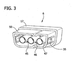
- Fig. 3 is a perspective of a mating side of the first connector of Figs. 1 and 2 ;
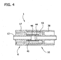
- Fig. 4 is a cross sectional view of the connector apparatus of Fig. 1 taken in a plane including line 4--4 on Fig. 1 ;
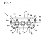
- Fig. 5 is a front elevation of the first connector of Fig. 1 ;
- Fig. 6 is a front elevation of a second embodiment of a connector
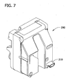
- Fig. 7 is a perspective of a controller of a compression therapy device incorporating the second connector of Fig. 2 ;
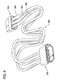
- Fig. 8 is a perspective of a tube set including a first connector and a second connector
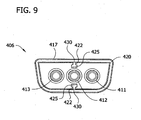
- Fig. 9 is a front elevation of a third embodiment of a connector
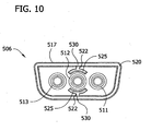
- Fig. 10 is a front elevation of a fourth embodiment of a connector
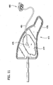
- Fig. 11 is a perspective of a compression therapy device including the connector of Fig. 9 .
- the connector apparatus 1 includes a first connector 6 and second connector 10.
- the first connector 6 includes a housing 17(broadly, "a body") and three tube ports 11,12,13 for attaching flexible tubes (not shown).
- the tube ports 11,12,13 are sized and shaped for being received in an end of a flexible tube to establish fluid communication between with the flexible tube and the tube port.
- the tube ports 11,12,13 project along an axis and have an exterior surface suitable for forming a seal with an interior surface of the flexible tube.
- the housing 17 includes a shroud 20 which projects outwardly from the housing.
- the shroud 20 generally surrounds the tube ports 11,12,13.
- Retainers 22 project from the shroud 20 in a radial direction toward the outer two tube ports 11,13 to restrain lateral movement of the flexible tube with respect to the tube ports 11,13 as will be described more fully hereinafter. Restrain lateral movement may include permitting some limited lateral movement of the tube. Moreover, the restrainers may or may not contact the flexible tube before some lateral movement of the tube on the tube port.
- the first connector 6 comprises two resilient latches 35 (one on each side of the first connector) for connection of the first connector and the second connector 10.
- the second connector 10 includes a housing 38 and connector ports 52,53,54 formed as one piece with the housing.
- the second connector 10 includes two latch receiving members 33 and mating catch holes 36.
- the latch receiving members 33 include deflecting portions 42 for deflecting respective resilient latches 35 inward so that ears at the distal ends of the latches can be received within the catch holes 36 upon connection of the first connector 6 and second connector 10. This releasably secures the first and second connectors 6, 10 together.
- the ears can be manually deflected out of the catch holes 36 to release the connectors 6,10 from each other.
- Other constructions for releasably securing the first and second connectors together may be used.
- structure for locking the connectors together may be omitted without departing from the scope of the present invention as defined in the appended claims.
- the connectors 6,10 are keyed to require a predetermined orientation of the first and second connectors where connected.
- Two guide rails 40 extend from the housing 38 of the second connector 10 for alignment of the first connector 6 and the second connector.
- the guide rails 40 are adapted to be slidingly received within two corresponding grooves 43 (one shown) of the first connector 6.
- the rails 40 and grooves 43 guide the connectors 6, 10 straight together upon connection.
- the exterior shapes of the portion of the housing 17 of the first connector 6 (i.e., male portion 50) and the portion of the second connector housing 38 receiving the male portion are also shaped to require a particular orientation of the connectors 6, 10 for connection.
- Other configurations for alignment and orientation may be used, or the connectors may have no alignment or guidance features within the scope of the present invention, as defined in the appended claims.
- three connector ports 45, 46, 47 are formed as one piece with the housing 17.
- the connector ports 45, 46, 47 are sized and shaped for connecting the connector ports in fluid communication with the fluid passage of an object such as the connector ports 52,53,54 of the second connector 10.
- the connector ports 45, 46, 47 are in fluid communication with the tube ports 11,12,13 of the first connector 6.
- the housing 17 includes the male portion 50, which is sized and shaped to be received in the second connector 10.
- the section of the mated first and second connectors 6, 10 shown in Fig. 4 passes through connector port 46 of the first connector 6.
- the connector port 46 includes a port stem 41 and a gasket 44 attached to the port stem.
- the gasket 44 may be made of any material sufficient to provide a fluid-tight seal with the connector port 53 such as polyvinylchloride (PVC).
- PVC polyvinylchloride
- the gasket 44 may be attached to the port stem 41 in a suitable manner such as by adhesive.
- Other constructions for achieving a fluid tight connection of the connector ports 45, 46, 47 of the first connector 6 with the connector ports 52, 53, 54 of the second connector 10 may be used within the scope of the present invention, as defined in the appended claims.
- the guide rails 40 are aligned with the grooves 43 and force is applied such that the housing 17 of the first connector 6 is received within the housing 38 of the second connector 10 (see, Fig. 2 ).
- the connector ports 45,46,47 of the first connector 6 ( Fig. 3 ) receive the connector ports 52,53,54 of the second connector 10.
- the resilient latches 35 are received within the latch receiving members 33.
- the resilient latches 35 are forced inward by the deflecting portions 42 (only one is shown) of the latch receiving members 33.
- the housing 17 of the first connector 6 advances into the housing 38 of the second connector until the resilient latches 35 are received within the mating cavities 36 to secure the connectors together.
- Each tube retainer 22 comprises, according to the invention, a rib 30 which projects from the shroud 20 toward the tube ports 11,13.
- the retainers 22 also include an engaging end portion 25 attached to each rib 30 and disposed in relation to the tube ports 11,13.
- Each rib 30 is relatively thin and is generally coextensive with the adjacent tube port (11 or 13).
- the engaging portion 25 (broadly, “engaging portion member”) extends generally transversely to the rib 30 so that, as seen end on in Fig. 5 , the retainer 22 has a generally "T" shaped configuration. Other configurations are permitted, but this embodiment provides material savings while also being sufficiently robust.
- the engaging end portions 25 are in radially opposed relation with a portion of the exterior surface of the tube ports 11,13.
- the engaging end portions 25 engage the flexible tubes (or are located in close proximity to the flexible tubes) when the tube ports 11,13 are received in the flexible tubes to restrain the flexible tubes from lateral movement with respect to the tube ports.
- the retainers 22 are in radially opposed relation to the tube ports 11,13 along the entire axis of the tube ports ( Fig. 2 ). It is within the scope of the present invention, as defined in the appended claims, that the retainers may be in radially opposed relation to the tube ports along less than the entire axis of the tube ports, however, it is preferred that the retainers oppose the tube ports at least at the distal end of the tube ports in order to prevent forces being applied to the tube ports that would result in separation of the tube port from the connector housing. Moreover, the number of the retainers and the arrangement may be other than illustrated.
- the center port 12 is shown as having no corresponding retainers, as the engagement of the tube on the center port 12 with the tubes on either side would restrain the tubes on the center port from substantial lateral movement.
- retainers (not shown) could be positioned next to the center port 12 also.
- Engaging end portions 25 generally have an arcuate rounded surface.
- the engaging end portions 25 may form a variety of shapes and surfaces for engaging the flexible tube within the scope of the present invention, as defined in the appended claims.
- engaging end portions 125 of retainers 122 of connector 106 have the shape of a cylindrical segment.
- the connector 106 is similar to the connector 6, and corresponding parts of the connector 106 will be designated by the same reference numbers as connector 6, plus "100".
- Ribs 130 extend from the shroud 120. The ribs 130 are spaced apart to effectively support the engaging end portions 125 and each engaging end portion extends continuously between three ribs.
- a shape of the end portion 125 whether a shorter arc like end portion 25 or a cylindrical segment 125, that corresponds to the shape of the tube to be engaged by the end portion is preferred.
- the first connector 6, 106 can be mated to objects other than the second connector 10 without departing from the scope of the present invention, as defined in the appended claims.
- the second connector can be in fluid communication with a variety of objects including a controller 290 of a compression therapy device ( Fig. 7 ) or a tube set 380 ( Fig. 8 ).
- the controller 290 of a sequential compression therapy device includes a second connector 210 which is in fluid communication with a source of pressurized air.
- the second connector 210 may have substantially the same configuration as the connector 10.
- the pressurized air is generated by a pump within the controller 290.
- the connector 210 is adapted for receiving the first connector 6 illustrated in Fig. 1 , or the connector 106 of Fig. 6 .
- the tube set 380 is illustrated.
- the tube set is capable of interconnecting the controller 290 ( Fig. 7 ) with a compression therapy device such as a compression therapy device for application to the leg.
- the tube set 380 comprises three tubes 382, 383, 384.
- the first connector 306 includes three tube ports 311, 312, 313 attached to the three tubes 382, 383, 384.
- the first connector 306 is also adapted for connection to the controller 290 ( Fig. 7 ) of a compression therapy device.
- the second connector 310 is attached to the three tubes 382, 383, 384 at opposite ends of the tubes from the first connector 306.
- the second connector 310 may be adapted for connection to a compression therapy device, for example a compression therapy device for application to the leg as shown and disclosed in U.S. Publ. No. 2005/0187503 .
- the first and second connectors 306, 310 of the tube set 380 correspond to the first and second connectors 6, 10 of Figs. 1-5 .
- the first connectors 6, 106 illustrated in Figs. 5 and 6 include retainers 22, 122 which restrain the flexible tubes attached to the outer two tube ports 11, 13, 111, 113.
- the first connector 6, 106 may be configured to restrain any number of flexible tubes including each flexible tube attached to the connector or only one of the flexible tubes attached to the connector within the scope of the present invention, as defined in the appended claims. Connectors with greater or fewer than three tube ports are also contemplated.
- a first connector 406 includes a middle tube port 412 with retainers 422 disposed in relation to the tube port 412. Except as described, the construction of the first connector 406 is substantially the same as connector 6, and corresponding parts of the first connector 406 are given the same reference number as for connector 6, plus "400.”
- the retainers 422 comprise ribs 430 which project from the shroud 420 and engaging end portions 425 that restrain the flexible tube from lateral movement with respect to the tube port 412.
- a first connector 406 includes a middle tube port 412 with retainers 422 disposed in relation to the tube port 412.
- the retainers 422 comprise ribs 430 which project from the shroud 420 and arcuate engaging end portions 425 that restrain the flexible tube from lateral movement with respect to the tube port 412.
- a compression therapy device for use with a source of air pressure includes a bladder 477 located with a wrap 478 sized and shaped for being applied to the foot.
- the compression therapy device 475 includes a bladder connector 479 for fluid communication between the bladder 477 and a flexible tube 481.
- the flexible tube is connected at one end to the first connector 406.
- the first connector 406 is illustrated in detail in Fig. 9 and includes retainers 422 to restrain the flexible tube 481 from lateral movement with respect to the tube port.
- the first connector 406 is adapted to be releasably secured to a source of air pressure such as the second connector 210 of the controller 290 illustrated in Fig. 7 or the second connector 310 of the tube set 380 illustrated in Fig. 8 .
Landscapes
- Engineering & Computer Science (AREA)
- Health & Medical Sciences (AREA)
- General Engineering & Computer Science (AREA)
- Mechanical Engineering (AREA)
- Heart & Thoracic Surgery (AREA)
- Veterinary Medicine (AREA)
- General Health & Medical Sciences (AREA)
- Public Health (AREA)
- Life Sciences & Earth Sciences (AREA)
- Animal Behavior & Ethology (AREA)
- Anesthesiology (AREA)
- Pulmonology (AREA)
- Biomedical Technology (AREA)
- Hematology (AREA)
- Rehabilitation Therapy (AREA)
- Pain & Pain Management (AREA)
- Epidemiology (AREA)
- Physical Education & Sports Medicine (AREA)
- Infusion, Injection, And Reservoir Apparatuses (AREA)
Claims (16)
- Connecteur (6, 106, 306, 406, 506) pour fixer au moins un tube flexible à un passage de fluide d'un autre objet, le connecteur (6, 106, 306, 406, 506) comprenant un corps (17, 117, 417, 517), au moins un port de connecteur (45, 46, 47) sur le corps (17, 117, 417, 517) dimensionné et configuré pour connecter le port de connecteur en communication fluidique avec le passage de fluide de l'objet, au moins un orifice de tube (11 ; 12, 13, 111, 112, 113, 411, 412, 413, 511, 512, 513) faisant saillie du corps (17, 117, 417, 517) conçu pour une communication du fluide avec le port de connecteur (45, 46, 47), l'orifice de tube (11, 12, 13, 111, 112, 113, 411, 412, 413, 511, 512, 513) étant dimensionné et configuré pour être reçu dans une extrémité du tube flexible pour établir une communication fluidique avec le tube flexible,
caractérisé par
un organe de retenue de tube (22, 122, 422, 522) faisant saillie du corps (17, 117, 417, 517) vers l'orifice de tube (11, 12, 13, 111, 112, 113, 411, 412, 413, 511, 512, 513) et ayant une portion d'extrémité d'engagement (25, 125, 425, 525) disposée relativement à l'orifice de tube pour venir en prise avec le tube flexible lorsque l'orifice de tube est reçu dans le tube flexible pour restreindre un déplacement latéral du tube flexible relativement à l'orifice de tube, où l'organe de retenue de tube (22, 122, 422, 522) comprend au moins une nervure (30, 130, 430, 530) faisant saillie du corps (17, 117, 417, 517), la portion d'extrémité d'engagement (25, 125, 425, 525) s'étendant généralement transversalement de la nervure (30, 130, 430, 530). - Connecteur (6, 106, 306, 406, 506) selon la revendication 1, dans lequel l'orifice de tube (11, 12, 13, 111, 112, 113, 411, 412, 413, 511, 512, 513) fait saillie le long d'un axe et possède une surface extérieure, la portion d'extrémité de l'organe de retenue de tube (22, 122, 422, 522) étant en une relation radialement opposée avec au moins une portion de la surface extérieure de l'orifice de tube (11, 12, 13, 111, 112, 113, 411, 412, 413, 511, 512, 513).
- Connecteur (6, 106, 306, 406, 506) selon la revendication 1 ou 2, dans lequel l'organe de retenue de tube (22, 122, 422, 522) se trouve en une relation radialement opposée avec une portion d'extrémité distale de l'orifice de tube (11, 12, 13, 111, 112, 113, 411, 412, 413, 511, 512, 513).
- Connecteur (6, 106, 306, 406, 506) selon la revendication 1, 2 ou 3, dans lequel la portion d'extrémité d'engagement (25, 125, 425, 525) possède une surface arquée.
- Connecteur (106) selon la revendication 4, dans lequel la portion d'extrémité d'engagement (125) a la forme d'un segment cylindrique.
- Connecteur (6, 106, 306, 406, 506) selon la revendication 1, dans lequel l'organe de retenue de tube (22, 122, 422, 522) comprend plusieurs nervures espacées (30, 130, 430, 530) faisant saillie du corps (17, 117, 417, 517).
- Connecteur (106) selon la revendication 6, dans lequel la portion d'extrémité d'engagement (125) s'étend continuellement entre les nervures (130).
- Connecteur (6, 406, 506) selon la revendication 6, dans lequel la portion d'engagement (25, 425, 525) comprend des éléments de portion d'engagement séparés, chacun associé à une nervure respective des nervures (30, 430, 530).
- Connecteur (6, 106, 306, 406, 506) selon l'une quelconque des revendications 6 à 8, dans lequel le corps (17, 117, 417, 517) comprend une enveloppe (20, 120, 420, 520) faisant saillie vers l'extérieur du corps et entourant généralement les orifices de tube, la nervure (30, 130, 430, 530) faisant saillie de l'enveloppe.
- Connecteur (6, 106, 306, 406, 506) selon l'une quelconque des revendications 1 à 7, comprenant en outre plusieurs orifices de tube (11, 12, 13, 111, 112, 113, 411, 412, 413, 511, 512, 513) et plusieurs organes de retenue de tube (22, 122, 422, 522).
- Connecteur (6, 106, 306, 406, 506) selon l'une des revendications 1 à 7 en combinaison avec le tube flexible recevant l'orifice de tube (11, 12, 13, 111, 112, 113, 411, 412, 413, 511, 512, 513) dans celui-ci.
- Système de compression utilisé pour appliquer une pression à un appendice d'un patient, comprenant :une pompe à air (290) pour fournir de l'air sous pression et ayant un passage de fluide ;au moins un tube flexible ;un connecteur (6, 106, 306, 406, 506) selon l'une des revendications 1 à 11, apte à être fixé à la sortie de la pompe à air (290) et pour fixer ledit au moins un tube flexible à un passage de fluide d'un autre objet.
- Système de compression selon la revendication 12, comprenant en outre plusieurs tubes flexibles, plusieurs orifices de tube (11, 12, 13, 111, 112, 113, 411, 412, 413, 511, 512, 513) et plusieurs organes de retenue de tube (22, 122, 422, 522).
- Dispositif de thérapie à compression (475) pour utilisation avec une source de pression d'air (290) ayant un passage de fluide, le dispositif de thérapie à compression (475) comprenant au moins une vessie d'air (477) dimensionnée et configurée pour être appliquée à un appendice d'un patient et en communication fluidique avec un tube flexible (481) et un connecteur (406) selon l'une des revendications 1 à 10 connecté au tube,
le port de connecteur sur le corps étant dimensionné et configuré pour connecter le port de connecteur en communication fluidique avec le passage de fluide de la source de pression d'air (290). - Dispositif de thérapie à compression (475) selon la revendication 14, où le dispositif de thérapie à compression comprend une vessie (477) dimensionnée et configurée pour être appliqué au pied.
- Dispositif de thérapie à compression (475) selon la revendication 14 ou 15, comprenant en outre plusieurs tubes flexibles, plusieurs orifices de tube (411, 412, 413) et un organe de retenue de tube (422) pour chaque orifice de tube.
Applications Claiming Priority (1)
| Application Number | Priority Date | Filing Date | Title |
|---|---|---|---|
| US11/750,452 US8092409B2 (en) | 2007-05-18 | 2007-05-18 | Reinforced connector |
Publications (3)
| Publication Number | Publication Date |
|---|---|
| EP1992861A2 EP1992861A2 (fr) | 2008-11-19 |
| EP1992861A3 EP1992861A3 (fr) | 2013-07-10 |
| EP1992861B1 true EP1992861B1 (fr) | 2014-10-01 |
Family
ID=39682645
Family Applications (1)
| Application Number | Title | Priority Date | Filing Date |
|---|---|---|---|
| EP08156212.6A Active EP1992861B1 (fr) | 2007-05-18 | 2008-05-15 | Connecteur renforcé |
Country Status (3)
| Country | Link |
|---|---|
| US (3) | US8092409B2 (fr) |
| EP (1) | EP1992861B1 (fr) |
| ES (1) | ES2525227T3 (fr) |
Families Citing this family (55)
| Publication number | Priority date | Publication date | Assignee | Title |
|---|---|---|---|---|
| US9642759B2 (en) | 2007-04-13 | 2017-05-09 | Stryker Corporation | Patient support with universal energy supply system |
| US8092409B2 (en) * | 2007-05-18 | 2012-01-10 | Tyco Healthcare Group Lp | Reinforced connector |
| JP5577868B2 (ja) * | 2010-06-11 | 2014-08-27 | 住友電装株式会社 | ガス配管用コネクタ |
| JP5447975B2 (ja) * | 2010-06-29 | 2014-03-19 | 住友電装株式会社 | ガス分配ユニット |
| USD686328S1 (en) * | 2010-10-12 | 2013-07-16 | Physio-Control, Inc. | Plug and socket for temperature monitoring probe of patient monitor |
| CA2838698A1 (fr) * | 2011-06-08 | 2012-12-13 | Nxstage Medical, Inc. | Procedes, dispositifs, et systemes pour raccorder entre eux des conduits de fluides |
| US10773863B2 (en) | 2011-06-22 | 2020-09-15 | Sartorius Stedim North America Inc. | Vessel closures and methods for using and manufacturing same |
| AU2012294959C1 (en) | 2011-08-10 | 2025-03-06 | Fisher & Paykel Healthcare Limited | Conduit connector for a patient breathing device |
| US20130138143A1 (en) * | 2011-11-26 | 2013-05-30 | Gennady Chechelnitsky | Acupressure device with a plurality of individually-controlled applicators having protrusions extending therefrom |
| USD721435S1 (en) * | 2013-01-15 | 2015-01-20 | Research Institute At Nationwide Children's Hospital | Medical marking apparatus |
| KR101558979B1 (ko) | 2013-06-18 | 2015-10-13 | (주)한미홈케어 | 온수매트용 관 연결 장치 |
| WO2015024594A1 (fr) * | 2013-08-21 | 2015-02-26 | Cedic S. R. L. | Dispositif de valve sans aiguille |
| USD743510S1 (en) | 2013-10-31 | 2015-11-17 | Nordson Corporation | High pressure fluid conduit connector components and connector assembly |
| US9534721B2 (en) | 2013-10-31 | 2017-01-03 | Nordson Corporation | High pressure fluid conduit connector components and connector assembly |
| CN112891694B (zh) | 2015-03-31 | 2026-03-17 | 费雪派克医疗保健有限公司 | 用于在呼吸支持系统中使用的设备 |
| CN108472468B (zh) * | 2015-09-04 | 2024-03-08 | 费雪派克医疗保健有限公司 | 导管连接器 |
| US10667984B2 (en) | 2015-12-18 | 2020-06-02 | Stryker Corporation | Systems and methods for operating patient therapy devices |
| EP3246052A1 (fr) * | 2016-05-20 | 2017-11-22 | Fresenius Medical Care | Raccord de tube |
| USD809656S1 (en) | 2016-06-10 | 2018-02-06 | Fisher & Paykel Healthcare Limited | Connector for a breathing circuit |
| CN109689003A (zh) * | 2016-09-06 | 2019-04-26 | 费德维尔有限责任公司 | 用于按摩人体乳房的设备 |
| DE202017101060U1 (de) * | 2017-02-24 | 2018-05-25 | Fct Electronic Gmbh | Steckverbinder, insbesondere für eine Hochstromanwendung |
| USD872700S1 (en) * | 2017-04-12 | 2020-01-14 | Roxtec Ab | Frame for sealing cables |
| US11410771B2 (en) | 2017-06-01 | 2022-08-09 | Stryker Corporation | Patient care devices with open communication |
| CN107387918A (zh) * | 2017-07-21 | 2017-11-24 | 珠海格力电器股份有限公司 | 滤芯组件与水路板的连接结构及包括其的净水机 |
| CN107595572A (zh) * | 2017-08-15 | 2018-01-19 | 广东泰宝医疗器械技术研究院有限公司 | 一种多通道的气路形腔 |
| EP3710361A4 (fr) | 2017-11-14 | 2021-08-11 | Sartorius Stedim North America Inc. | Ensemble de transfert de fluide avec une jonction ayant de multiples voies de fluide |
| US11691866B2 (en) | 2017-11-14 | 2023-07-04 | Sartorius Stedim North America Inc. | System for simultaneous distribution of fluid to multiple vessels and method of using the same |
| US11319201B2 (en) | 2019-07-23 | 2022-05-03 | Sartorius Stedim North America Inc. | System for simultaneous filling of multiple containers |
| US11577953B2 (en) | 2017-11-14 | 2023-02-14 | Sartorius Stedim North America, Inc. | System for simultaneous distribution of fluid to multiple vessels and method of using the same |
| US12252391B2 (en) | 2017-11-14 | 2025-03-18 | Sartorius Stedim North America Inc. | System for simultaneous distribution of fluid to multiple vessels and method of using the same |
| NL2020013B1 (en) * | 2017-12-04 | 2019-06-11 | Crea Ip B V | Multi-lumen luer connector |
| CN108644508A (zh) * | 2018-07-20 | 2018-10-12 | 珠海格力电器股份有限公司 | 一种一体式水路板连接结构及净水装置 |
| US10998665B2 (en) | 2018-11-15 | 2021-05-04 | Medline Industries, Inc. | Hybrid connector |
| KR102179175B1 (ko) * | 2019-03-11 | 2020-11-16 | (주)선메딕스 | 이동형 사지 압박 순환장치 |
| EP3952976A4 (fr) | 2019-04-09 | 2022-12-28 | NxStage Medical, Inc. | Procédés, dispositifs et systèmes pour raccorder entre elles des conduites fluidiques |
| US10737049B1 (en) * | 2019-08-05 | 2020-08-11 | Dynasthetics, Llc | Apparatus for connecting oxygen delivery control instrument to patient delivery device |
| USD1006981S1 (en) | 2019-09-06 | 2023-12-05 | Fisher & Paykel Healthcare Limited | Breathing conduit |
| USD948027S1 (en) | 2019-09-10 | 2022-04-05 | Fisher & Paykel Healthcare Limited | Connector for a breathing conduit |
| DE102020201428A1 (de) * | 2020-02-06 | 2021-08-12 | Alfmeier Präzision SE | Verbindungselement und Versorgungsleiste für eine Ventilanordnung |
| USD940861S1 (en) | 2020-03-03 | 2022-01-11 | Fisher & Paykel Healthcare Limited | Connector for a respiratory system conduit |
| USD963161S1 (en) * | 2020-05-22 | 2022-09-06 | Kpr U.S., Llc | Fluid connector |
| USD961769S1 (en) * | 2020-05-22 | 2022-08-23 | Kpr U.S., Llc | Fluid connector |
| JP7490823B2 (ja) * | 2020-05-22 | 2024-05-27 | ケーピーアール ユー.エス.,エルエルシー | 可逆的なコネクタを利用するシステム、方法、及びデバイス |
| USD974551S1 (en) | 2020-12-09 | 2023-01-03 | Fisher & Paykel Healthcare Limited | Connector assembly and connector |
| USD1073919S1 (en) | 2021-05-17 | 2025-05-06 | Fisher & Paykel Healthcare Limited | Respiratory system conduit with connector |
| USD999883S1 (en) * | 2021-05-24 | 2023-09-26 | Kpr U.S., Llc | Fluid connector |
| USD1001248S1 (en) * | 2021-05-24 | 2023-10-10 | Kpr U.S., Llc | Fluid connector |
| USD1001247S1 (en) * | 2021-05-24 | 2023-10-10 | Kpr U.S., Llc | Fluid connector |
| USD1001249S1 (en) * | 2021-05-24 | 2023-10-10 | Kpr U.S., Llc | Fluid connector |
| USD1013162S1 (en) * | 2021-05-24 | 2024-01-30 | Kpr U.S., Llc | Fluid connector |
| USD993406S1 (en) * | 2021-05-24 | 2023-07-25 | Kpr U.S., Llc | Fluid connector |
| USD995758S1 (en) | 2021-06-11 | 2023-08-15 | Fisher & Paykel Healthcare Limited | Tube assembly and connector |
| US12239127B2 (en) | 2021-07-28 | 2025-03-04 | Sartorius Stedim North America Inc. | Thermal capacitors, systems, and methods for rapid freezing or heating of biological materials |
| CN114177033A (zh) * | 2021-12-30 | 2022-03-15 | 深圳市东吉联医疗科技有限公司 | 一种空气波理疗仪装置 |
| US20260027288A1 (en) * | 2022-07-17 | 2026-01-29 | Sage Products Llc | Medical Tube Management Systems and Methods |
Family Cites Families (46)
| Publication number | Priority date | Publication date | Assignee | Title |
|---|---|---|---|---|
| US369813A (en) * | 1887-09-13 | Gustav eabee | ||
| US1181481A (en) * | 1911-05-16 | 1916-05-02 | Joseph Vincent Robinson | Automatic interlocking coupling. |
| US1578368A (en) * | 1920-03-10 | 1926-03-30 | Joseph V Robinson | Automatic train-pipe connecter |
| US1936015A (en) * | 1932-10-07 | 1933-11-21 | Arthur C Harrell | Automatic train pipe coupling |
| US2628850A (en) * | 1949-03-19 | 1953-02-17 | Donald V Summerville | Releasable conduit connection with automatic valving |
| USRE29054E (en) * | 1970-12-02 | 1976-11-30 | Apparatus for attaching a hot and cold water plumbing fixture to building water pipes | |
| US4253449A (en) * | 1979-08-09 | 1981-03-03 | The Kendall Company | Compression device with connection system |
| JPS5666590A (en) * | 1979-11-05 | 1981-06-05 | Aisin Seiki | Hose connector for pipings |
| DE2946315C2 (de) * | 1979-11-16 | 1983-04-28 | Gewerkschaft Eisenhütte Westfalia, 4670 Lünen | Steckkupplung für hydraulische Schlauchleitungsbündel zur Verwendung bei Maschinen und Apparaten des untertägigen Bergbaus |
| US4280485A (en) * | 1980-04-11 | 1981-07-28 | The Kendall Company | Compression device with simulator |
| DE3041641A1 (de) * | 1980-11-05 | 1982-06-09 | Günter van Dr.med. 4000 Düsseldorf Endert | Vorrichtung zur herstellung eines schlauchanschlusses |
| US4801162A (en) * | 1981-04-24 | 1989-01-31 | Honeywell Inc. | Integral strain relief for fluidic devices |
| US4804208A (en) * | 1986-08-11 | 1989-02-14 | The Kendall Company | Manifold coupling assembly |
| IT220672Z2 (it) * | 1990-11-13 | 1993-10-11 | Itw Fastex Italia Spa | Dispositivo di collegamento a scatto, a tenuta di fluido, per tubazioni |
| USD333293S (en) * | 1991-08-20 | 1993-02-16 | Nintendo Co., Ltd. | Electrical connector for a video game system |
| US5236227B1 (en) * | 1991-11-12 | 1996-12-03 | Opti Com Manufacturing Network | Assembly for connecting multi-duct conduits having tapered alignment walls |
| US5234185A (en) * | 1992-02-21 | 1993-08-10 | General Motors Corporation | Unitary pipe clamp and assembly |
| USD357736S (en) * | 1993-09-16 | 1995-04-25 | The Kendall Company | Connector for device for applying compressive pressure to the leg |
| US5478119A (en) * | 1993-09-16 | 1995-12-26 | The Kendall Company | Polarized manifold connection device |
| USD373191S (en) * | 1994-04-05 | 1996-08-27 | Jobst Institute, Inc. | Multi-channel conduit connector for treating deep vein thrombosis |
| US5588954A (en) * | 1994-04-05 | 1996-12-31 | Beiersdorf-Jobst, Inc. | Connector for a gradient sequential compression system |
| USD364459S (en) * | 1994-04-26 | 1995-11-21 | The Kendall Company | Connector for applying compressive pressure to the leg |
| USD363988S (en) * | 1994-04-26 | 1995-11-07 | The Kendall Company | Connector for applying compressive pressure to the leg |
| USD364460S (en) * | 1994-04-26 | 1995-11-21 | The Kendall Company | Connector for applying compressive pressure to the leg |
| USD373192S (en) * | 1994-11-09 | 1996-08-27 | The Kendall Company | Connector for a device for applying compressive pressure to the leg |
| US5662500A (en) * | 1996-04-08 | 1997-09-02 | Yeah; Solomon | Plug-and-socket power connector |
| US6007107A (en) * | 1996-07-12 | 1999-12-28 | Container Technology, Inc. | Fluid coupling for matching delivery and supply lines irrespective of the relative rotational positions of the coupling members |
| US5951059A (en) * | 1996-07-24 | 1999-09-14 | Tokai Rubber Industries Ltd. | Tube connector device having connector holder made of elastomer |
| USD396695S (en) * | 1997-08-04 | 1998-08-04 | Lantek Electronics Inc. | Adapter |
| US6062244A (en) * | 1998-08-13 | 2000-05-16 | Aci Medical | Fluidic connector |
| USD460417S1 (en) * | 2000-10-19 | 2002-07-16 | Tvm Group, Inc. | Socket connector with pin and socket type aligners |
| USD460046S1 (en) * | 2000-10-19 | 2002-07-09 | Tvm Group, Inc. | Pin connector with pin and socket type aligners |
| GB2373444A (en) | 2001-03-23 | 2002-09-25 | Clotsox Ltd | Inflatable compression sleeve |
| US6871878B2 (en) * | 2002-04-12 | 2005-03-29 | Cool Systems, Inc. | Make-break connector for heat exchanger |
| US6827728B2 (en) * | 2002-08-08 | 2004-12-07 | Medivance Incorporated | Patient temperature control system |
| US6802855B2 (en) * | 2002-08-08 | 2004-10-12 | Medivance Incorporated | Patient temperature control system connector apparatus |
| US7163531B2 (en) * | 2002-08-19 | 2007-01-16 | Baxter International, Inc. | User-friendly catheter connection adapters for optimized connection to multiple lumen catheters |
| US6926311B2 (en) * | 2003-09-03 | 2005-08-09 | Apex Medical Corp. | Apparatus for quick connection |
| GB0330203D0 (en) * | 2003-12-31 | 2004-02-04 | Novamedix Distrib Ltd | Garment for use in pump therapy for enhancing venous and arterial blood flow |
| US7490620B2 (en) * | 2004-02-23 | 2009-02-17 | Tyco Healthcare Group Lp | Fluid conduit connector apparatus |
| US7871387B2 (en) | 2004-02-23 | 2011-01-18 | Tyco Healthcare Group Lp | Compression sleeve convertible in length |
| US7282038B2 (en) | 2004-02-23 | 2007-10-16 | Tyco Healthcare Group Lp | Compression apparatus |
| USD516514S1 (en) * | 2004-02-24 | 2006-03-07 | Tyco Electronics Corporation | High current power connector |
| USD601248S1 (en) | 2007-05-18 | 2009-09-29 | Tyco Healthcare Group Lp | Connector and port arrangement with cylindrical segment tube retainers |
| USD595845S1 (en) | 2007-05-18 | 2009-07-07 | Tyco Healthcare Group Lp | Connector and port arrangement with arcuate tube retainers |
| US8092409B2 (en) * | 2007-05-18 | 2012-01-10 | Tyco Healthcare Group Lp | Reinforced connector |
-
2007
- 2007-05-18 US US11/750,452 patent/US8092409B2/en active Active
-
2008
- 2008-05-15 EP EP08156212.6A patent/EP1992861B1/fr active Active
- 2008-05-15 ES ES08156212.6T patent/ES2525227T3/es active Active
-
2012
- 2012-01-03 US US13/342,386 patent/US8585622B2/en active Active
-
2013
- 2013-11-01 US US14/069,473 patent/US9161877B2/en active Active
Also Published As
| Publication number | Publication date |
|---|---|
| ES2525227T3 (es) | 2014-12-19 |
| EP1992861A2 (fr) | 2008-11-19 |
| US20140058301A1 (en) | 2014-02-27 |
| US20120109030A1 (en) | 2012-05-03 |
| US20080287843A1 (en) | 2008-11-20 |
| US9161877B2 (en) | 2015-10-20 |
| EP1992861A3 (fr) | 2013-07-10 |
| US8585622B2 (en) | 2013-11-19 |
| US8092409B2 (en) | 2012-01-10 |
Similar Documents
| Publication | Publication Date | Title |
|---|---|---|
| EP1992861B1 (fr) | Connecteur renforcé | |
| CA2601496C (fr) | Ensemble de raccords de securite | |
| US8257287B2 (en) | Safety connector assembly | |
| US5725485A (en) | Connector for a gradient sequential compression system | |
| US6319231B1 (en) | Medical connector | |
| CN1918422A (zh) | 流体管道连接装置 | |
| US12011205B2 (en) | Universal adaptor for gas scavenging systems | |
| US20250114267A1 (en) | System, method, and device utilizing reversible connector | |
| CN120344289A (zh) | 用于医疗管连接的套管 | |
| AU2012216461B2 (en) | Safety connector assembly | |
| US20240261175A1 (en) | System, method, and device utilizing reversible connector | |
| CN219413846U (zh) | 管道接头、基座和半导体激光治疗仪 | |
| CN219963419U (zh) | 一种改良型间歇气动压力装置 | |
| CN223914119U (zh) | 关节镜外鞘和关节镜套件 |
Legal Events
| Date | Code | Title | Description |
|---|---|---|---|
| PUAI | Public reference made under article 153(3) epc to a published international application that has entered the european phase |
Free format text: ORIGINAL CODE: 0009012 |
|
| AK | Designated contracting states |
Kind code of ref document: A2 Designated state(s): AT BE BG CH CY CZ DE DK EE ES FI FR GB GR HR HU IE IS IT LI LT LU LV MC MT NL NO PL PT RO SE SI SK TR |
|
| AX | Request for extension of the european patent |
Extension state: AL BA MK RS |
|
| PUAL | Search report despatched |
Free format text: ORIGINAL CODE: 0009013 |
|
| AK | Designated contracting states |
Kind code of ref document: A3 Designated state(s): AT BE BG CH CY CZ DE DK EE ES FI FR GB GR HR HU IE IS IT LI LT LU LV MC MT NL NO PL PT RO SE SI SK TR |
|
| AX | Request for extension of the european patent |
Extension state: AL BA MK RS |
|
| RIC1 | Information provided on ipc code assigned before grant |
Ipc: F16L 37/56 20060101AFI20130605BHEP Ipc: A61M 39/12 20060101ALI20130605BHEP Ipc: A61M 39/10 20060101ALI20130605BHEP Ipc: F16L 39/02 20060101ALI20130605BHEP |
|
| 17P | Request for examination filed |
Effective date: 20131031 |
|
| RBV | Designated contracting states (corrected) |
Designated state(s): AT BE BG CH CY CZ DE DK EE ES FI FR GB GR HR HU IE IS IT LI LT LU LV MC MT NL NO PL PT RO SE SI SK TR |
|
| 17Q | First examination report despatched |
Effective date: 20131209 |
|
| AKX | Designation fees paid |
Designated state(s): AT BE BG CH CY CZ DE DK EE ES FI FR GB GR HR HU IE IS IT LI LT LU LV MC MT NL NO PL PT RO SE SI SK TR |
|
| RIC1 | Information provided on ipc code assigned before grant |
Ipc: A61H 1/00 20060101ALI20140402BHEP Ipc: F16L 39/02 20060101ALI20140402BHEP Ipc: F16L 37/56 20060101AFI20140402BHEP Ipc: A61M 39/10 20060101ALI20140402BHEP Ipc: A61M 39/12 20060101ALI20140402BHEP |
|
| GRAP | Despatch of communication of intention to grant a patent |
Free format text: ORIGINAL CODE: EPIDOSNIGR1 |
|
| INTG | Intention to grant announced |
Effective date: 20140513 |
|
| GRAS | Grant fee paid |
Free format text: ORIGINAL CODE: EPIDOSNIGR3 |
|
| GRAA | (expected) grant |
Free format text: ORIGINAL CODE: 0009210 |
|
| AK | Designated contracting states |
Kind code of ref document: B1 Designated state(s): AT BE BG CH CY CZ DE DK EE ES FI FR GB GR HR HU IE IS IT LI LT LU LV MC MT NL NO PL PT RO SE SI SK TR |
|
| REG | Reference to a national code |
Ref country code: GB Ref legal event code: FG4D |
|
| REG | Reference to a national code |
Ref country code: CH Ref legal event code: EP Ref country code: AT Ref legal event code: REF Ref document number: 689710 Country of ref document: AT Kind code of ref document: T Effective date: 20141015 |
|
| REG | Reference to a national code |
Ref country code: IE Ref legal event code: FG4D |
|
| REG | Reference to a national code |
Ref country code: DE Ref legal event code: R096 Ref document number: 602008034638 Country of ref document: DE Effective date: 20141113 |
|
| REG | Reference to a national code |
Ref country code: ES Ref legal event code: FG2A Ref document number: 2525227 Country of ref document: ES Kind code of ref document: T3 Effective date: 20141219 |
|
| REG | Reference to a national code |
Ref country code: NL Ref legal event code: VDEP Effective date: 20141001 |
|
| REG | Reference to a national code |
Ref country code: AT Ref legal event code: MK05 Ref document number: 689710 Country of ref document: AT Kind code of ref document: T Effective date: 20141001 |
|
| REG | Reference to a national code |
Ref country code: LT Ref legal event code: MG4D |
|
| PG25 | Lapsed in a contracting state [announced via postgrant information from national office to epo] |
Ref country code: NL Free format text: LAPSE BECAUSE OF FAILURE TO SUBMIT A TRANSLATION OF THE DESCRIPTION OR TO PAY THE FEE WITHIN THE PRESCRIBED TIME-LIMIT Effective date: 20141001 |
|
| PG25 | Lapsed in a contracting state [announced via postgrant information from national office to epo] |
Ref country code: NO Free format text: LAPSE BECAUSE OF FAILURE TO SUBMIT A TRANSLATION OF THE DESCRIPTION OR TO PAY THE FEE WITHIN THE PRESCRIBED TIME-LIMIT Effective date: 20150101 Ref country code: PT Free format text: LAPSE BECAUSE OF FAILURE TO SUBMIT A TRANSLATION OF THE DESCRIPTION OR TO PAY THE FEE WITHIN THE PRESCRIBED TIME-LIMIT Effective date: 20150202 Ref country code: CZ Free format text: LAPSE BECAUSE OF FAILURE TO SUBMIT A TRANSLATION OF THE DESCRIPTION OR TO PAY THE FEE WITHIN THE PRESCRIBED TIME-LIMIT Effective date: 20141001 Ref country code: LT Free format text: LAPSE BECAUSE OF FAILURE TO SUBMIT A TRANSLATION OF THE DESCRIPTION OR TO PAY THE FEE WITHIN THE PRESCRIBED TIME-LIMIT Effective date: 20141001 Ref country code: IS Free format text: LAPSE BECAUSE OF FAILURE TO SUBMIT A TRANSLATION OF THE DESCRIPTION OR TO PAY THE FEE WITHIN THE PRESCRIBED TIME-LIMIT Effective date: 20150201 Ref country code: FI Free format text: LAPSE BECAUSE OF FAILURE TO SUBMIT A TRANSLATION OF THE DESCRIPTION OR TO PAY THE FEE WITHIN THE PRESCRIBED TIME-LIMIT Effective date: 20141001 |
|
| PG25 | Lapsed in a contracting state [announced via postgrant information from national office to epo] |
Ref country code: GR Free format text: LAPSE BECAUSE OF FAILURE TO SUBMIT A TRANSLATION OF THE DESCRIPTION OR TO PAY THE FEE WITHIN THE PRESCRIBED TIME-LIMIT Effective date: 20150102 Ref country code: HR Free format text: LAPSE BECAUSE OF FAILURE TO SUBMIT A TRANSLATION OF THE DESCRIPTION OR TO PAY THE FEE WITHIN THE PRESCRIBED TIME-LIMIT Effective date: 20141001 Ref country code: LV Free format text: LAPSE BECAUSE OF FAILURE TO SUBMIT A TRANSLATION OF THE DESCRIPTION OR TO PAY THE FEE WITHIN THE PRESCRIBED TIME-LIMIT Effective date: 20141001 Ref country code: CY Free format text: LAPSE BECAUSE OF FAILURE TO SUBMIT A TRANSLATION OF THE DESCRIPTION OR TO PAY THE FEE WITHIN THE PRESCRIBED TIME-LIMIT Effective date: 20141001 Ref country code: PL Free format text: LAPSE BECAUSE OF FAILURE TO SUBMIT A TRANSLATION OF THE DESCRIPTION OR TO PAY THE FEE WITHIN THE PRESCRIBED TIME-LIMIT Effective date: 20141001 Ref country code: SE Free format text: LAPSE BECAUSE OF FAILURE TO SUBMIT A TRANSLATION OF THE DESCRIPTION OR TO PAY THE FEE WITHIN THE PRESCRIBED TIME-LIMIT Effective date: 20141001 Ref country code: AT Free format text: LAPSE BECAUSE OF FAILURE TO SUBMIT A TRANSLATION OF THE DESCRIPTION OR TO PAY THE FEE WITHIN THE PRESCRIBED TIME-LIMIT Effective date: 20141001 |
|
| REG | Reference to a national code |
Ref country code: DE Ref legal event code: R097 Ref document number: 602008034638 Country of ref document: DE |
|
| PG25 | Lapsed in a contracting state [announced via postgrant information from national office to epo] |
Ref country code: DK Free format text: LAPSE BECAUSE OF FAILURE TO SUBMIT A TRANSLATION OF THE DESCRIPTION OR TO PAY THE FEE WITHIN THE PRESCRIBED TIME-LIMIT Effective date: 20141001 Ref country code: EE Free format text: LAPSE BECAUSE OF FAILURE TO SUBMIT A TRANSLATION OF THE DESCRIPTION OR TO PAY THE FEE WITHIN THE PRESCRIBED TIME-LIMIT Effective date: 20141001 Ref country code: SK Free format text: LAPSE BECAUSE OF FAILURE TO SUBMIT A TRANSLATION OF THE DESCRIPTION OR TO PAY THE FEE WITHIN THE PRESCRIBED TIME-LIMIT Effective date: 20141001 Ref country code: RO Free format text: LAPSE BECAUSE OF FAILURE TO SUBMIT A TRANSLATION OF THE DESCRIPTION OR TO PAY THE FEE WITHIN THE PRESCRIBED TIME-LIMIT Effective date: 20141001 |
|
| PLBE | No opposition filed within time limit |
Free format text: ORIGINAL CODE: 0009261 |
|
| STAA | Information on the status of an ep patent application or granted ep patent |
Free format text: STATUS: NO OPPOSITION FILED WITHIN TIME LIMIT |
|
| 26N | No opposition filed |
Effective date: 20150702 |
|
| REG | Reference to a national code |
Ref country code: CH Ref legal event code: PL |
|
| PG25 | Lapsed in a contracting state [announced via postgrant information from national office to epo] |
Ref country code: LI Free format text: LAPSE BECAUSE OF NON-PAYMENT OF DUE FEES Effective date: 20150531 Ref country code: MC Free format text: LAPSE BECAUSE OF FAILURE TO SUBMIT A TRANSLATION OF THE DESCRIPTION OR TO PAY THE FEE WITHIN THE PRESCRIBED TIME-LIMIT Effective date: 20141001 Ref country code: LU Free format text: LAPSE BECAUSE OF FAILURE TO SUBMIT A TRANSLATION OF THE DESCRIPTION OR TO PAY THE FEE WITHIN THE PRESCRIBED TIME-LIMIT Effective date: 20150515 Ref country code: CH Free format text: LAPSE BECAUSE OF NON-PAYMENT OF DUE FEES Effective date: 20150531 |
|
| REG | Reference to a national code |
Ref country code: IE Ref legal event code: MM4A |
|
| PG25 | Lapsed in a contracting state [announced via postgrant information from national office to epo] |
Ref country code: SI Free format text: LAPSE BECAUSE OF FAILURE TO SUBMIT A TRANSLATION OF THE DESCRIPTION OR TO PAY THE FEE WITHIN THE PRESCRIBED TIME-LIMIT Effective date: 20141001 |
|
| REG | Reference to a national code |
Ref country code: FR Ref legal event code: PLFP Year of fee payment: 9 |
|
| PG25 | Lapsed in a contracting state [announced via postgrant information from national office to epo] |
Ref country code: IE Free format text: LAPSE BECAUSE OF NON-PAYMENT OF DUE FEES Effective date: 20150515 |
|
| PG25 | Lapsed in a contracting state [announced via postgrant information from national office to epo] |
Ref country code: MT Free format text: LAPSE BECAUSE OF FAILURE TO SUBMIT A TRANSLATION OF THE DESCRIPTION OR TO PAY THE FEE WITHIN THE PRESCRIBED TIME-LIMIT Effective date: 20141001 |
|
| REG | Reference to a national code |
Ref country code: FR Ref legal event code: PLFP Year of fee payment: 10 |
|
| PG25 | Lapsed in a contracting state [announced via postgrant information from national office to epo] |
Ref country code: HU Free format text: LAPSE BECAUSE OF FAILURE TO SUBMIT A TRANSLATION OF THE DESCRIPTION OR TO PAY THE FEE WITHIN THE PRESCRIBED TIME-LIMIT; INVALID AB INITIO Effective date: 20080515 Ref country code: BG Free format text: LAPSE BECAUSE OF FAILURE TO SUBMIT A TRANSLATION OF THE DESCRIPTION OR TO PAY THE FEE WITHIN THE PRESCRIBED TIME-LIMIT Effective date: 20141001 |
|
| PG25 | Lapsed in a contracting state [announced via postgrant information from national office to epo] |
Ref country code: TR Free format text: LAPSE BECAUSE OF FAILURE TO SUBMIT A TRANSLATION OF THE DESCRIPTION OR TO PAY THE FEE WITHIN THE PRESCRIBED TIME-LIMIT Effective date: 20141001 |
|
| PG25 | Lapsed in a contracting state [announced via postgrant information from national office to epo] |
Ref country code: BE Free format text: LAPSE BECAUSE OF FAILURE TO SUBMIT A TRANSLATION OF THE DESCRIPTION OR TO PAY THE FEE WITHIN THE PRESCRIBED TIME-LIMIT Effective date: 20141001 |
|
| REG | Reference to a national code |
Ref country code: GB Ref legal event code: 732E Free format text: REGISTERED BETWEEN 20180111 AND 20180117 |
|
| REG | Reference to a national code |
Ref country code: FR Ref legal event code: PLFP Year of fee payment: 11 |
|
| REG | Reference to a national code |
Ref country code: FR Ref legal event code: TP Owner name: CARDINAL HEALTH IRELAND UNLIMITED COMPANY, IE Effective date: 20180629 |
|
| REG | Reference to a national code |
Ref country code: ES Ref legal event code: PC2A Owner name: CARDINAL HEALTH IRELAND UNLIMITED COMPANY Effective date: 20181121 |
|
| REG | Reference to a national code |
Ref country code: GB Ref legal event code: 732E Free format text: REGISTERED BETWEEN 20200514 AND 20200520 |
|
| PGFP | Annual fee paid to national office [announced via postgrant information from national office to epo] |
Ref country code: DE Payment date: 20250529 Year of fee payment: 18 |
|
| PGFP | Annual fee paid to national office [announced via postgrant information from national office to epo] |
Ref country code: ES Payment date: 20250602 Year of fee payment: 18 Ref country code: GB Payment date: 20250527 Year of fee payment: 18 |
|
| PGFP | Annual fee paid to national office [announced via postgrant information from national office to epo] |
Ref country code: IT Payment date: 20250521 Year of fee payment: 18 |
|
| PGFP | Annual fee paid to national office [announced via postgrant information from national office to epo] |
Ref country code: FR Payment date: 20250526 Year of fee payment: 18 |