EP1992870A2 - Configuration d'illuminateurs allongés pour écrans LCD - Google Patents
Configuration d'illuminateurs allongés pour écrans LCD Download PDFInfo
- Publication number
- EP1992870A2 EP1992870A2 EP08156311A EP08156311A EP1992870A2 EP 1992870 A2 EP1992870 A2 EP 1992870A2 EP 08156311 A EP08156311 A EP 08156311A EP 08156311 A EP08156311 A EP 08156311A EP 1992870 A2 EP1992870 A2 EP 1992870A2
- Authority
- EP
- European Patent Office
- Prior art keywords
- light
- elongated
- illuminator
- solid
- illuminators
- Prior art date
- Legal status (The legal status is an assumption and is not a legal conclusion. Google has not performed a legal analysis and makes no representation as to the accuracy of the status listed.)
- Withdrawn
Links
- 239000007787 solid Substances 0.000 claims abstract description 75
- 238000002156 mixing Methods 0.000 claims abstract description 69
- 230000008878 coupling Effects 0.000 claims abstract description 10
- 238000010168 coupling process Methods 0.000 claims abstract description 10
- 238000005859 coupling reaction Methods 0.000 claims abstract description 10
- 238000000605 extraction Methods 0.000 claims description 72
- 239000010408 film Substances 0.000 description 50
- 238000005286 illumination Methods 0.000 description 30
- 230000006870 function Effects 0.000 description 18
- 239000000463 material Substances 0.000 description 15
- 230000003287 optical effect Effects 0.000 description 14
- 239000013307 optical fiber Substances 0.000 description 14
- 239000000853 adhesive Substances 0.000 description 12
- 230000001070 adhesive effect Effects 0.000 description 12
- 238000013461 design Methods 0.000 description 12
- 238000009826 distribution Methods 0.000 description 12
- 230000037361 pathway Effects 0.000 description 10
- 229920000642 polymer Polymers 0.000 description 10
- 239000012790 adhesive layer Substances 0.000 description 9
- 238000013459 approach Methods 0.000 description 9
- 230000001976 improved effect Effects 0.000 description 9
- 229920003229 poly(methyl methacrylate) Polymers 0.000 description 9
- 239000004926 polymethyl methacrylate Substances 0.000 description 9
- 230000010287 polarization Effects 0.000 description 8
- 230000007480 spreading Effects 0.000 description 8
- 238000003892 spreading Methods 0.000 description 8
- 230000008901 benefit Effects 0.000 description 6
- 238000000034 method Methods 0.000 description 6
- 230000003595 spectral effect Effects 0.000 description 6
- 230000003667 anti-reflective effect Effects 0.000 description 5
- 238000000149 argon plasma sintering Methods 0.000 description 5
- 239000003086 colorant Substances 0.000 description 5
- 239000004973 liquid crystal related substance Substances 0.000 description 5
- 238000004519 manufacturing process Methods 0.000 description 5
- WYTGDNHDOZPMIW-RCBQFDQVSA-N alstonine Natural products C1=CC2=C3C=CC=CC3=NC2=C2N1C[C@H]1[C@H](C)OC=C(C(=O)OC)[C@H]1C2 WYTGDNHDOZPMIW-RCBQFDQVSA-N 0.000 description 4
- 238000005452 bending Methods 0.000 description 4
- 230000005540 biological transmission Effects 0.000 description 4
- 230000008859 change Effects 0.000 description 4
- 150000001875 compounds Chemical class 0.000 description 4
- 239000000835 fiber Substances 0.000 description 4
- 238000003384 imaging method Methods 0.000 description 4
- 239000010410 layer Substances 0.000 description 4
- 101100248200 Arabidopsis thaliana RGGB gene Proteins 0.000 description 3
- 239000004593 Epoxy Substances 0.000 description 3
- 239000011324 bead Substances 0.000 description 3
- 238000005253 cladding Methods 0.000 description 3
- 238000001914 filtration Methods 0.000 description 3
- 239000000203 mixture Substances 0.000 description 3
- 239000004417 polycarbonate Substances 0.000 description 3
- 229920000515 polycarbonate Polymers 0.000 description 3
- 238000007665 sagging Methods 0.000 description 3
- NIXOWILDQLNWCW-UHFFFAOYSA-N acrylic acid group Chemical group C(C=C)(=O)O NIXOWILDQLNWCW-UHFFFAOYSA-N 0.000 description 2
- 239000000654 additive Substances 0.000 description 2
- 239000006117 anti-reflective coating Substances 0.000 description 2
- 238000005266 casting Methods 0.000 description 2
- 230000003750 conditioning effect Effects 0.000 description 2
- 238000001816 cooling Methods 0.000 description 2
- 230000000694 effects Effects 0.000 description 2
- 230000002708 enhancing effect Effects 0.000 description 2
- 239000011521 glass Substances 0.000 description 2
- 239000000178 monomer Substances 0.000 description 2
- 238000005457 optimization Methods 0.000 description 2
- 238000005498 polishing Methods 0.000 description 2
- 229920002492 poly(sulfone) Polymers 0.000 description 2
- 229920006267 polyester film Polymers 0.000 description 2
- 230000005855 radiation Effects 0.000 description 2
- 239000004065 semiconductor Substances 0.000 description 2
- 238000007493 shaping process Methods 0.000 description 2
- 230000008093 supporting effect Effects 0.000 description 2
- 230000003746 surface roughness Effects 0.000 description 2
- 238000011282 treatment Methods 0.000 description 2
- 238000007514 turning Methods 0.000 description 2
- 229920000089 Cyclic olefin copolymer Polymers 0.000 description 1
- 241000272168 Laridae Species 0.000 description 1
- 239000004952 Polyamide Substances 0.000 description 1
- 238000010521 absorption reaction Methods 0.000 description 1
- 230000003213 activating effect Effects 0.000 description 1
- 230000004913 activation Effects 0.000 description 1
- 230000032683 aging Effects 0.000 description 1
- 230000003466 anti-cipated effect Effects 0.000 description 1
- 230000000712 assembly Effects 0.000 description 1
- 238000000429 assembly Methods 0.000 description 1
- 230000009286 beneficial effect Effects 0.000 description 1
- 239000011230 binding agent Substances 0.000 description 1
- 238000010382 chemical cross-linking Methods 0.000 description 1
- 238000003486 chemical etching Methods 0.000 description 1
- 230000001427 coherent effect Effects 0.000 description 1
- 239000002131 composite material Substances 0.000 description 1
- 239000012141 concentrate Substances 0.000 description 1
- 229920001577 copolymer Polymers 0.000 description 1
- 238000009792 diffusion process Methods 0.000 description 1
- 230000009977 dual effect Effects 0.000 description 1
- 238000010894 electron beam technology Methods 0.000 description 1
- 238000004049 embossing Methods 0.000 description 1
- 238000005516 engineering process Methods 0.000 description 1
- 230000007613 environmental effect Effects 0.000 description 1
- 125000003700 epoxy group Chemical group 0.000 description 1
- 230000002349 favourable effect Effects 0.000 description 1
- 238000007524 flame polishing Methods 0.000 description 1
- 239000003292 glue Substances 0.000 description 1
- 238000010438 heat treatment Methods 0.000 description 1
- 239000012943 hotmelt Substances 0.000 description 1
- 230000006872 improvement Effects 0.000 description 1
- 230000010365 information processing Effects 0.000 description 1
- 239000007788 liquid Substances 0.000 description 1
- 238000003754 machining Methods 0.000 description 1
- 239000011159 matrix material Substances 0.000 description 1
- 238000005259 measurement Methods 0.000 description 1
- 230000007246 mechanism Effects 0.000 description 1
- QSHDDOUJBYECFT-UHFFFAOYSA-N mercury Chemical compound [Hg] QSHDDOUJBYECFT-UHFFFAOYSA-N 0.000 description 1
- 229910052753 mercury Inorganic materials 0.000 description 1
- 229910052751 metal Inorganic materials 0.000 description 1
- 239000002184 metal Substances 0.000 description 1
- 238000012986 modification Methods 0.000 description 1
- 230000004048 modification Effects 0.000 description 1
- 238000012544 monitoring process Methods 0.000 description 1
- 238000000465 moulding Methods 0.000 description 1
- 239000012788 optical film Substances 0.000 description 1
- 239000002245 particle Substances 0.000 description 1
- 238000000059 patterning Methods 0.000 description 1
- 230000002093 peripheral effect Effects 0.000 description 1
- 239000000049 pigment Substances 0.000 description 1
- 239000004033 plastic Substances 0.000 description 1
- 229920003023 plastic Polymers 0.000 description 1
- 229920002647 polyamide Polymers 0.000 description 1
- 229920000647 polyepoxide Polymers 0.000 description 1
- 229920000728 polyester Polymers 0.000 description 1
- 229920006254 polymer film Polymers 0.000 description 1
- 229920000098 polyolefin Polymers 0.000 description 1
- 229920001296 polysiloxane Polymers 0.000 description 1
- 230000008569 process Effects 0.000 description 1
- 230000000644 propagated effect Effects 0.000 description 1
- 230000001902 propagating effect Effects 0.000 description 1
- 230000009467 reduction Effects 0.000 description 1
- 238000002310 reflectometry Methods 0.000 description 1
- 230000010076 replication Effects 0.000 description 1
- 230000004044 response Effects 0.000 description 1
- 239000005336 safety glass Substances 0.000 description 1
- 238000007650 screen-printing Methods 0.000 description 1
- 238000000926 separation method Methods 0.000 description 1
- 239000002904 solvent Substances 0.000 description 1
- 230000035882 stress Effects 0.000 description 1
- 238000004381 surface treatment Methods 0.000 description 1
- 238000012876 topography Methods 0.000 description 1
- 230000007704 transition Effects 0.000 description 1
- 239000012780 transparent material Substances 0.000 description 1
Images












Classifications
-
- G—PHYSICS
- G02—OPTICS
- G02F—OPTICAL DEVICES OR ARRANGEMENTS FOR THE CONTROL OF LIGHT BY MODIFICATION OF THE OPTICAL PROPERTIES OF THE MEDIA OF THE ELEMENTS INVOLVED THEREIN; NON-LINEAR OPTICS; FREQUENCY-CHANGING OF LIGHT; OPTICAL LOGIC ELEMENTS; OPTICAL ANALOGUE/DIGITAL CONVERTERS
- G02F1/00—Devices or arrangements for the control of the intensity, colour, phase, polarisation or direction of light arriving from an independent light source, e.g. switching, gating or modulating; Non-linear optics
- G02F1/01—Devices or arrangements for the control of the intensity, colour, phase, polarisation or direction of light arriving from an independent light source, e.g. switching, gating or modulating; Non-linear optics for the control of the intensity, phase, polarisation or colour
- G02F1/13—Devices or arrangements for the control of the intensity, colour, phase, polarisation or direction of light arriving from an independent light source, e.g. switching, gating or modulating; Non-linear optics for the control of the intensity, phase, polarisation or colour based on liquid crystals, e.g. single liquid crystal display cells
- G02F1/133—Constructional arrangements; Operation of liquid crystal cells; Circuit arrangements
- G02F1/1333—Constructional arrangements; Manufacturing methods
- G02F1/1335—Structural association of cells with optical devices, e.g. polarisers or reflectors
-
- G—PHYSICS
- G02—OPTICS
- G02B—OPTICAL ELEMENTS, SYSTEMS OR APPARATUS
- G02B6/00—Light guides; Structural details of arrangements comprising light guides and other optical elements, e.g. couplings
- G02B6/0001—Light guides; Structural details of arrangements comprising light guides and other optical elements, e.g. couplings specially adapted for lighting devices or systems
- G02B6/0011—Light guides; Structural details of arrangements comprising light guides and other optical elements, e.g. couplings specially adapted for lighting devices or systems the light guides being planar or of plate-like form
- G02B6/0033—Means for improving the coupling-out of light from the light guide
- G02B6/0035—Means for improving the coupling-out of light from the light guide provided on the surface of the light guide or in the bulk of it
- G02B6/0038—Linear indentations or grooves, e.g. arc-shaped grooves or meandering grooves, extending over the full length or width of the light guide
-
- G—PHYSICS
- G02—OPTICS
- G02B—OPTICAL ELEMENTS, SYSTEMS OR APPARATUS
- G02B6/00—Light guides; Structural details of arrangements comprising light guides and other optical elements, e.g. couplings
-
- G—PHYSICS
- G02—OPTICS
- G02B—OPTICAL ELEMENTS, SYSTEMS OR APPARATUS
- G02B6/00—Light guides; Structural details of arrangements comprising light guides and other optical elements, e.g. couplings
- G02B6/0001—Light guides; Structural details of arrangements comprising light guides and other optical elements, e.g. couplings specially adapted for lighting devices or systems
- G02B6/0005—Light guides; Structural details of arrangements comprising light guides and other optical elements, e.g. couplings specially adapted for lighting devices or systems the light guides being of the fibre type
- G02B6/001—Light guides; Structural details of arrangements comprising light guides and other optical elements, e.g. couplings specially adapted for lighting devices or systems the light guides being of the fibre type the light being emitted along at least a portion of the lateral surface of the fibre
-
- G—PHYSICS
- G02—OPTICS
- G02B—OPTICAL ELEMENTS, SYSTEMS OR APPARATUS
- G02B6/00—Light guides; Structural details of arrangements comprising light guides and other optical elements, e.g. couplings
- G02B6/0001—Light guides; Structural details of arrangements comprising light guides and other optical elements, e.g. couplings specially adapted for lighting devices or systems
- G02B6/0011—Light guides; Structural details of arrangements comprising light guides and other optical elements, e.g. couplings specially adapted for lighting devices or systems the light guides being planar or of plate-like form
- G02B6/0013—Means for improving the coupling-in of light from the light source into the light guide
- G02B6/0015—Means for improving the coupling-in of light from the light source into the light guide provided on the surface of the light guide or in the bulk of it
- G02B6/002—Means for improving the coupling-in of light from the light source into the light guide provided on the surface of the light guide or in the bulk of it by shaping at least a portion of the light guide, e.g. with collimating, focussing or diverging surfaces
-
- G—PHYSICS
- G02—OPTICS
- G02B—OPTICAL ELEMENTS, SYSTEMS OR APPARATUS
- G02B6/00—Light guides; Structural details of arrangements comprising light guides and other optical elements, e.g. couplings
- G02B6/0001—Light guides; Structural details of arrangements comprising light guides and other optical elements, e.g. couplings specially adapted for lighting devices or systems
- G02B6/0011—Light guides; Structural details of arrangements comprising light guides and other optical elements, e.g. couplings specially adapted for lighting devices or systems the light guides being planar or of plate-like form
- G02B6/0033—Means for improving the coupling-out of light from the light guide
- G02B6/0035—Means for improving the coupling-out of light from the light guide provided on the surface of the light guide or in the bulk of it
- G02B6/004—Scattering dots or dot-like elements, e.g. microbeads, scattering particles, nanoparticles
- G02B6/0043—Scattering dots or dot-like elements, e.g. microbeads, scattering particles, nanoparticles provided on the surface of the light guide
-
- G—PHYSICS
- G02—OPTICS
- G02B—OPTICAL ELEMENTS, SYSTEMS OR APPARATUS
- G02B6/00—Light guides; Structural details of arrangements comprising light guides and other optical elements, e.g. couplings
- G02B6/0001—Light guides; Structural details of arrangements comprising light guides and other optical elements, e.g. couplings specially adapted for lighting devices or systems
- G02B6/0011—Light guides; Structural details of arrangements comprising light guides and other optical elements, e.g. couplings specially adapted for lighting devices or systems the light guides being planar or of plate-like form
- G02B6/0033—Means for improving the coupling-out of light from the light guide
- G02B6/0035—Means for improving the coupling-out of light from the light guide provided on the surface of the light guide or in the bulk of it
- G02B6/0045—Means for improving the coupling-out of light from the light guide provided on the surface of the light guide or in the bulk of it by shaping at least a portion of the light guide
- G02B6/0046—Tapered light guide, e.g. wedge-shaped light guide
-
- G—PHYSICS
- G02—OPTICS
- G02B—OPTICAL ELEMENTS, SYSTEMS OR APPARATUS
- G02B6/00—Light guides; Structural details of arrangements comprising light guides and other optical elements, e.g. couplings
- G02B6/0001—Light guides; Structural details of arrangements comprising light guides and other optical elements, e.g. couplings specially adapted for lighting devices or systems
- G02B6/0011—Light guides; Structural details of arrangements comprising light guides and other optical elements, e.g. couplings specially adapted for lighting devices or systems the light guides being planar or of plate-like form
- G02B6/0066—Light guides; Structural details of arrangements comprising light guides and other optical elements, e.g. couplings specially adapted for lighting devices or systems the light guides being planar or of plate-like form characterised by the light source being coupled to the light guide
- G02B6/0068—Arrangements of plural sources, e.g. multi-colour light sources
-
- G—PHYSICS
- G02—OPTICS
- G02B—OPTICAL ELEMENTS, SYSTEMS OR APPARATUS
- G02B6/00—Light guides; Structural details of arrangements comprising light guides and other optical elements, e.g. couplings
- G02B6/0001—Light guides; Structural details of arrangements comprising light guides and other optical elements, e.g. couplings specially adapted for lighting devices or systems
- G02B6/0011—Light guides; Structural details of arrangements comprising light guides and other optical elements, e.g. couplings specially adapted for lighting devices or systems the light guides being planar or of plate-like form
- G02B6/0075—Arrangements of multiple light guides
- G02B6/0078—Side-by-side arrangements, e.g. for large area displays
-
- G—PHYSICS
- G02—OPTICS
- G02B—OPTICAL ELEMENTS, SYSTEMS OR APPARATUS
- G02B6/00—Light guides; Structural details of arrangements comprising light guides and other optical elements, e.g. couplings
- G02B6/0001—Light guides; Structural details of arrangements comprising light guides and other optical elements, e.g. couplings specially adapted for lighting devices or systems
- G02B6/0011—Light guides; Structural details of arrangements comprising light guides and other optical elements, e.g. couplings specially adapted for lighting devices or systems the light guides being planar or of plate-like form
- G02B6/0013—Means for improving the coupling-in of light from the light source into the light guide
- G02B6/0015—Means for improving the coupling-in of light from the light source into the light guide provided on the surface of the light guide or in the bulk of it
- G02B6/002—Means for improving the coupling-in of light from the light source into the light guide provided on the surface of the light guide or in the bulk of it by shaping at least a portion of the light guide, e.g. with collimating, focussing or diverging surfaces
- G02B6/0021—Means for improving the coupling-in of light from the light source into the light guide provided on the surface of the light guide or in the bulk of it by shaping at least a portion of the light guide, e.g. with collimating, focussing or diverging surfaces for housing at least a part of the light source, e.g. by forming holes or recesses
-
- G—PHYSICS
- G02—OPTICS
- G02B—OPTICAL ELEMENTS, SYSTEMS OR APPARATUS
- G02B6/00—Light guides; Structural details of arrangements comprising light guides and other optical elements, e.g. couplings
- G02B6/0001—Light guides; Structural details of arrangements comprising light guides and other optical elements, e.g. couplings specially adapted for lighting devices or systems
- G02B6/0011—Light guides; Structural details of arrangements comprising light guides and other optical elements, e.g. couplings specially adapted for lighting devices or systems the light guides being planar or of plate-like form
- G02B6/0033—Means for improving the coupling-out of light from the light guide
- G02B6/005—Means for improving the coupling-out of light from the light guide provided by one optical element, or plurality thereof, placed on the light output side of the light guide
- G02B6/0053—Prismatic sheet or layer; Brightness enhancement element, sheet or layer
-
- G—PHYSICS
- G02—OPTICS
- G02B—OPTICAL ELEMENTS, SYSTEMS OR APPARATUS
- G02B6/00—Light guides; Structural details of arrangements comprising light guides and other optical elements, e.g. couplings
- G02B6/0001—Light guides; Structural details of arrangements comprising light guides and other optical elements, e.g. couplings specially adapted for lighting devices or systems
- G02B6/0011—Light guides; Structural details of arrangements comprising light guides and other optical elements, e.g. couplings specially adapted for lighting devices or systems the light guides being planar or of plate-like form
- G02B6/0033—Means for improving the coupling-out of light from the light guide
- G02B6/005—Means for improving the coupling-out of light from the light guide provided by one optical element, or plurality thereof, placed on the light output side of the light guide
- G02B6/0055—Reflecting element, sheet or layer
Definitions
- This invention relates to the art of backlight apparatus for a display and a liquid crystal display employing such apparatus.
- the present invention relates to a Liquid Crystal Display (LCD) backlight with solid-state light sources.
- LCD Liquid Crystal Display
- LCDs liquid crystal displays
- CRT cathode ray tube
- CCFL cold cathode fluorescent
- Conventional flat panel backlight solutions using sidemounted CCFLs are less and less desirable as display size increases and, particularly as display area grows, can be susceptible to warping in manufacture or due to heat.
- Light-guiding backlight techniques that are conventionally employed for smaller devices are increasingly hampered by low brightness or luminance levels and by problems related to poor uniformity as the display size increases, such as would be needed for digital TV, for example.
- Existing backlight apparatus for LCD displays and other display and illumination applications, often using banks of CCFLs lined up in parallel, can be relatively inefficient.
- LEDs Light-Emitting Diodes
- array arrangements used for an instrument panel.
- array arrangements do not appear promising, due to problems of poor color and brightness uniformity, high parts count, high heat, and dimensional requirements.
- Light guides have been employed for spreading light from a point source in order to form a line of light.
- U.S. Patent No. 5,499,112 entitled “Light Guide, Illuminating Device Having the Light Guide, and Image Reading Device and Information Processing Apparatus Having the Illuminating Device” to Kawai et al. discloses redirecting light from one or more LEDs to a line in a scanning apparatus, using a single light guide having extraction features distributed along its length.
- U.S. Patent No. 5,400,224 entitled “Lighting Panel” to DuNah et al. describes a molded panel assembly having multiple light guides that are treated with randomized roughness over a back surface for backlighting illumination.
- Another type of solution first directs the light from the LED, lamp, or other point source along a line, then spread this light over a panel.
- U.S. Patent No. 5,835,661 entitled “Light Expanding System for Producing a Linear or Planar Light Beam from a Point-Like Light Source” to Tai et al. describes a beam-expanding light pipe that directs a line of light to a light panel for distribution over an area.
- U.S. Patent No. 5,857,761 entitled “Illumination Device” to Abe et al. describes a light guide that spreads point source light into a light radiation plate.
- Still other backlighting solutions employ flexible optical fibers for directing light from a single light source, then treated for spreading the light for emission behind an LCD panel.
- Different versions of this approach are described, for example, in U.S. Patent No. 6,714,185 entitled “Back Lighting Apparatus of Liquid Crystal Display Using Optical Fiber” to Kim et al. and in U.S. Patent No. 5,542,016 entitled “Optical Fiber Light Emitting Apparatus” to Kaschke.
- LEDs and other solid-state light sources are inherently capable of providing 100% or more of the NTSC color gamut.
- three or more different-colored LEDs or other solid-state sources are needed.
- a high level of color mixing is required from the backlighting apparatus.
- solid-state light sources such as Red (R), Green (G), and Blue (B) LEDs
- the present invention provides a solid waveguide comprising opposite TIR surfaces further comprising:
- the invention also provides variations in the backlight apparatus and a display employing the backlight apparatus.
- a process for providing light is also disclosed. It is a feature of the present invention that it provides a backlight that utilizes multiple illumination channels.
- the apparatus of the present invention is scalable and is particularly adaptable to larger sized LC panels.
- the present invention provides a backlight apparatus that is well-suited to display applications, particularly for LC display panels, such as those used for LCD TV, medical diagnostics displays, imaging displays, and military displays, for example.
- the backlight apparatus of the present invention can be used for other illumination applications where solid-state lighting is advantageous.
- Solid-state light source has its conventional meaning accepted by those in the illumination arts, indicating a type of emissive light source formed from semiconductor materials.
- Solid-state light sources include, for example, Light-Emitting Diodes (LEDs), Organic Light Emitting Diodes (OLEDs) and (Polymer Light Emitting Diodes) PLEDs, as well as semiconductor lasers.
- LEDs Light-Emitting Diodes
- OLEDs Organic Light Emitting Diodes
- PLEDs Polymer Light Emitting Diodes
- semiconductor lasers semiconductor lasers.
- solid state light source as used herein means any source of light from a small point-like source but the design of the emission source may be such that the light being emitted is either collimated or spread so as to appear to be non-point-like.
- An array of several solid state light sources may be arranged in a manner or with lens elements so as to combine the light in a broader non-point-like source.
- a display panel is a transmissive spatial light-modulating device, such as an LC display device or other array of light valves.
- linear or elongated as used herein with respect to illuminator and light channels means much longer in length than in width, typically approaching the length of the display in one (length) direction but not nearly that long in the other (width) direction.
- the se terms may be straight or curved such as serpentine.
- Examples may include a variety of cross-sectional end-shapes such as square, rectilinear, round, triangular or they may be a composite shape of two or more shapes.
- At least one surface of the illuminators or light channels may comprise a means to extract or otherwise breakup or redirect the total internal reflection of the light channel. Such a means may to done in a manner provide uniform light appearance.
- Ra is a measure of the peak to valley height difference of a surface.
- Surface topography is of great importance in specifying the function of a surface. The roughness of a surface can be measured in different ways which are classified into three basic categories:
- the embodiments of US Serial Nos for Attorney Docket 93433 are incorporated herein by reference.
- the solid waveguides with elongated illuminator useful in this invention extend along an illumination plane and redirect light upward, in the direction of a display panel.
- the display panel and illumination plane are substantially in parallel.
- the primary direction of light from light channel array is upward and toward display panel.
- elongated illuminators could be disposed orthogonally so that they extend in the general direction of the x axis and are spaced apart by some distance along the y axis. In subsequent description and figures, extension along the y axis is shown, but the orthogonal arrangement could alternately be used.
- the elongated illuminators have a center to center spacing between elongated illuminators of less than 25mm.
- a type of, elongated illuminator light channel has a length dimension L that is well in excess of its width dimension W or thickness dimension T.
- length L is greater than 5 times width dimension W.
- width dimension W and thickness dimension T differ from each other by no more than a factor of 2.
- dimensions T and W are approximately equal. Maintaining dimensions W and T at much less than length L improves color mixing and uniformity, since light that is directed into elongated light channel 18 is propagated through this light-guiding structure by means of Total Internal Reflection (TIR). Because it uses TIR, elongated illuminator light channel is highly efficient, with very low light loss except in the intended direction as provided by light extraction element. In other embodiments useful in this invention the length of the elongated illuminators to the light input surface area has a ratio of greater than 100/1.
- Rigidity of solid elongated illuminator light channels helps to provide more uniform light output, since the distance between illumination plane and display panel is best kept constant.
- the descriptive term "rigidity" applies to an element that exhibits no visible bowing or bending due to its own weight. This arrangement also simplifies assembly of elongated light channels into light channel array.
- elongated light channel may be square, rectangular, or circular, or have some other shape.
- solid elongated light channel can have variously curved sidewalls for improved mixing of light from LED light sources.
- the cross-sectional shape or dimensions may change over the length of elongated light channel, so that elongated light channel is tapered, as shown in subsequent examples, or otherwise changes its cross-sectional shape.
- Useful embodiments may have more than one slope associated with the taper or in may be a radius with constantly changing slopes. In such embodiment it may also be useful to have a mixing section that starts at the light input surface and continue for a short distance. While long distance are useful, it has been found that a light mix section of between 20 and 60 millimeters is sufficient to provide good color mixing.
- the tapers as described herein are useful in providing uniform brightness along the length of the solid waveguides of this invention. It is desirable to provide waveguides that provide on-axis brightness of greater than 2000 cd/m 2 .
- RGB LEDs can be a significant challenge.
- a single LED might alternately be used, such as a white light LED.
- additional color LEDs can be used to increase brightness or enhance color gamut, such as to provide an RGGB arrangement or to add cyan, orange, or other colors.
- Other lighting arrangements are also possible, as is described in more detail subsequently.
- having more than one solid state light source per light input surface may be useful. For long lengths of elongated illuminators, having more than one light source per light input surface provides more light without having to run at high levels of power and risk potential burn out of the solid state light source. Having more than one light source also helps to assure that there is sufficient light to reach the far regions of the solid waveguide while maintaining sufficient brightness.
- the solid waveguide use in a display that is useful in this invention may further comprises at least one function selected from the group consisting of light diffusing, light collimation, brightness enhancement, light polarization, light modulating, light filtering, a light source. Such functions are useful in providing higher brightness, good on-axis as well as off-axis viewing. Light collimation, diffusion and scattering helps to manipulate light to provide the most pleasing viewing to the viewer.
- Light management films discussed above may include but are not limited to various types of light enhancement films or Brightness Enhancement Films (BEF), such as Vikuiti TM Thin Brightness Enhancement Film, a product of 3M, St. Paul, MN.
- BEF Brightness Enhancement Film
- Polarizers can also be provided, such as reflective polarizers.
- the films and their functions may be combined into a single film with more than one functionality.
- Elongated illuminators may be distributed in any of a number of configurations. The separation distance between adjacent elongated illuminators can be varied based on factors such as the needed brightness, area, and uniformity. Adjacent elongated illuminators can be adjacent, but not optically coupled.
- An integral bridge may join one or more elongated illuminators in part of the profile as shown in some of the figures in this invention. Such integral bridges are useful for providing improved stiffness and may also help to provide improved brightness uniformity between elongated illuminators.
- Fill factor can be an important consideration for achieving needed brightness levels, as well as for mixing spectral components where light sources of different wavelengths are used.
- Fill factor for each elongated illuminator would be computed as the ratio of the surface area of the one or more light sources that direct light into light channel to the incident light surface area of light channel.
- Fill factor for backlight apparatus would be computed as the ratio of the sum of the emissive areas of elongated illuminators to the surface area of illumination plane of the apparatus.
- Each elongated illuminator has at least one independent solid-state light source 16.
- Solid state light source can be independent in that it delivers light.
- Solid-state light sources 16 could be LEDs, as noted earlier. LEDs are advantaged due to their high brightness and good spectral characteristics. Providing direct light emission within narrow wavelength bands, LEDs are thus capable of providing illumination that offers an improved color gamut over conventional light sources. CCFL sources, for example, offer about 70% of the NTSC color gamut when used with an LCD panel. LED sources can achieve 100% or greater of the NTSC range. LEDs also are advantaged because they can be rapidly pulsed.
- Elongated illuminators and in particular solid waveguides with a mixing section of the present invention provide a high degree of color mixing for LEDs.
- the solid waveguide with elongated illuminators and mixing sections that form a light channel with relatively narrow width dimensions provide excellent color mixing.
- This arrangement yields a substantial number of reflections as light propagates through the mixing section and down the path provided by the elongated illuminators light channel.
- Red (R), Green (G), and Blue (B) LEDs can be positioned as an RGB triad of LEDs at one or both ends of light channel 18.
- An RGGB arrangement, with more than one LED of one or more colors could alternately be used to boost the green light level.
- R, G, and B LEDs could be distributed at different ends of light channel, so that, for example, a single light channel has a Red and a Green LED on one end and a Green and a Blue LED on the other end.
- a fourth LED such as a white light LED, or other color LED, could be positioned at one or both ends of light channel.
- each separate light channel could have a single color light source, so that, for example, three adjacent light channels have Red, Green, and Blue LEDs respectively.
- Dichroic filters could be used to direct light into individual elongated light channels
- Light sources can be continuously on, so that mixed RGB or white light is provided to display plane. Alternately, color sequential backlighting arrangements are possible.
- R, G, and B are rapidly cycled from backlight apparatus by activating the corresponding light sources 16 in sequence. Alternately, a linear scan can be provided, with R, G, and B or other colors provided in a scrolling sequence across the surface of backlight apparatus.
- a display plane can then activate corresponding rows or columns of pixels with the same sequence, providing sequential modulated color.
- Mixed colors such as cyan, magenta, and yellow could alternately be provided using timed activation of the light sources.
- Laser light sources could alternately be used with elongated illuminator of the present invention. Their relative spectral purity and fast response times make lasers an attractive alternative for some types of display applications.
- the high brightness and high optical power levels of lasers may allow a single source to illuminate multiple elongated illuminators light channels.
- Alternative light sources that are can be used with elongated illuminator may include Organic Light Emitting Diodes (OLEDs) and (Polymer Light Emitting Diodes) PLEDs.
- OLEDs Organic Light Emitting Diodes
- PLEDs Polymer Light Emitting Diodes
- Elongated illuminators light channels are formed from highly transparent materials, including various types of glass, such as a laminated safety glass.
- Plastics that can be used include PMMA, polycarbonate, polyester, polyamide, polysulfone, polyolefin, cyclic-olefin and copolymers thereof.
- Light channels may have additives for improved thermal and light stability. Optical transmission of the material should exceed about 90%. Except where intentionally treated, surfaces of light channel should have an optical finish. A high index of refraction n is preferred for its favorable light-guiding properties.
- elongated illuminators light channels could be cast, profile extruded or molded. Further conditioning of the material, such as by heating and polishing, could be beneficial for achieving improved optical performance. It is also useful to provide solid waveguide and elongated illuminators with a high degree of smoothness. Having a TIR surface with less than 50 nm Ra of roughness helps to minimize light leakage due to scattering when light hits a rough surface. Rough surfaces will breakup the TIR of the light and change its angle such that it may exit the elongated illuminator in an undesired point. This can reduce the overall effectiveness of the elongated illuminators.
- a high degree of stiffness or rigidity is advantageous for providing light channel as a modular component for a larger backplane apparatus.
- High stiffness allows for simple handling and ease of assembly of light pipe array.
- a stiffness in excess of 10 mN is preferred.
- a clip, holder, or other support can be used to help prevent sagging or bowing for light channels of longer length.
- Light channels should have a width W dimension that is sufficient to constrain bending. Additional support structures, if needed, can be used to prevent sideways bending.
- Elongated illuminators light channel may be separated from light source by some distance in the embodiments shown in the present application. However, it is also possible to embed light source within elongated light channel.
- the basic function of light redirecting features of elongated illuminator is to direct light that is otherwise being channeled by TIR and thereby cause light to be turned and then emitted from view side of the elongated light channel. This can be done in a number of ways, including the following:
- Light extraction features could be individual elements.
- the size and density of the coupled area may vary as a function of the distance along light channel from solid-state light source. For example, where there are LED light sources at each end of light channel, light extraction features could be distributed with higher density near the center than toward the ends. Alternately, the distribution density of light redirecting elements could be substantially continuous in one direction.
- Light redirecting may be provided on more than one surface.
- the opposite side of light channel, furthest from the LCD and output surface generally provides a smooth surface to prevent light leakage but may alternately be structured, treated, or roughened to enhance the amount of light extraction.
- Light redirecting elements may be molded into, embossed, pressed, adhered, printed or laminated to the of elongated illuminator light channel that faces display panel 24 or other light output side.
- an optional color sensor can be provided as a component of one or more elongated illuminators. Color sensor can be used in a control loop that compensates for color shifts such as can be due to ageing, heat, or manufacturing differences between LEDs or other types of light source. Optionally, image data for pixels nearest a particular light pipe can be adjusted to compensate for detected color shifts.
- a light mixing section that is an integral part of the elongated illuminators.
- the mixing section starts at the light input surface and may extend all or a part of the illuminator length.
- the light mixing sections may extend only a few millimeters and the balance of the elongated illuminator may be changed in its profile as shown by the various figures within this disclosure.
- the primary function is to mix light from several sources of different color temperatures, so it is desirable to have the mixing section to be substantially free of light directing features. This helps to assure that a true white that has all wavelengths mixed in a manner to provide a uniform color temperature to the solid waveguide and elongated illuminators.
- the solid waveguide and elongated illuminators of this invention may have a desired pattern of light redirecting features that comprises at least one selected from the group consisting of prisms, dots, reflectors, changing slope.
- the changing slope may comprise at least one taper starting at the light guide side of said at least one mixing section.
- the taper terminates at least in one of the group selected from the group consisting of the center, the opposite side said at least one light emitting section, the opposite end of said light guide, a reflector.
- the solid waveguide with a taper comprises a radius.
- the solid waveguide may have tapers with at least two different slopes. Such embodiments help to provide uniform light propagation of light.
- the taper may further be designed and coordinated with the design of the light redirection features to provide uniform light illumination and good viewing of the display.
- Solid waveguide of this invention may further comprises a bridge connecting at least two said at least at least one elongated illuminators.
- the bridge is useful in holding the elongated illuminators in a fixed position in relation to each other as well as to provide added strength to minimize sagging of the elongated illuminators.
- the bridge may be applied to the elongated illuminators or it may be formed as an integral part of the waveguide.
- the bridge When the bride is on the viewing side of the display, the bridge may be a thin flat surface that is useful in holding other films at a fixed distance from the illuminators. In some embodiments the bridge may be used to bond other films to it.
- the flat surface may also be further textured or featured to add additional functionality to the waveguide and display.
- Such wavguides may be formed directing in a mold or machined to obtained the desired shape.
- the solid waveguide of this invention may further comprise at least one elongated illuminator has an end cross sectional profile selected from the group consisting of square, rectangular, triangular, round.
- the solid waveguide of this invention may further comprise at least one elongated illuminator that further comprises a region to spread light sideways towards said at least one light emitting surface.
- Such embodiments are useful in providing uniform light between elongated illuminators.
- the solid waveguide this invention may also further comprise a region between the elongated illuminators that comprise a means of redirecting light substantially towards said light emitting surface. Such embodiments are shown in the figures of this invention.
- the region between may be roughened, curved or structured to help provide uniform illumination between the elongated illuminators. To better achieve this it may be desirable to provide solid waveguide wherein the elongated illuminator comprises a means for side light emitting.
- the solid waveguide of this invention may have an optical fiber as the elongated illuminators wherein said at least one elongated illuminator an optical fiber.
- Such fiber may further comprise regions of controlled light leakage. Such controlled leakage is useful in providing higher brightness along the length og the illuminator and has a means to extract it it the dsired location to help provide uniform lighting.
- elongated illuminator that further provides a TIR cladding.
- the TIT cladding is a material with a different refractive index than that of the core. Such cladding are useful in propagating light long distances with the elongated illuminators.
- a solid comprises at least one light mixing section substantially outside of the view area of a light guide.
- light from a soild state light source can be mixed to provide uniform color temperature white light in a solid waveguide.
- a traditional light guide plate can provide well mixed and uniform color temperature white light.
- the solid waveguide of of this invention may also be part of a display.
- the display may further comprises at least one function selected from the group consisting of light diffusing, light collimation, brightness enhancement, light polarization, light modulating, light filtering, a light source.
- the embodiments of this invention further comprise a light source and in particular a solid state light source.
- the waveguides useful in this invention may be made from a variety of materials such as polycarbonate, polysulfone, UV cured monomers as well as PMMA.
- PMMA is preferred because it has a high level of transmission and may be processed in a variety of means to form a solid waveguide as well as elongated illuminators. Additional the PMMA has a high level of stiffness and may be optically polhised or formed directly to minimize scattering within the elongated illuminators and thereby maximize the transmission of light along it length as well as when light is redirected towards the light emitting side.
- the solid waveguide of this invention may have a surface roughness (Ra) of less than 25 nm.
- the surface may be provided with a roughness greater than 25 nm. This roughness may also be provided in a pattern to redirect light to a specific location for a special effect.
- the surface Ra may be obtained by flame polishing, a combination of liquid grit known as optical polishing compounds or by casting or extruding it against a very smooth surface. (combination of the above may be used).
- Another means to obtain a desired smoothness may be to flood coat the surface with a polymer allowing it to flow and film and surface not uniformities. It such a case it may be desirable to match the refractive index of the polymer and the PMMA.
- the solid waveguides of this invention may designed to provide a brightness uniformity of less than 10% along it length. This in part can be achieved by controlling the design of the light redirecting features in terns of their height, density, size, location, included angle or roughness.
- the basic design of the elongated illuminator may also be changed in their cross sectional profile as well as providing excellent of light coupling into the light input surface of the solid waveguide and elongated illuminators. The objective is to provide the highest level of light entering the elongated illuminators as possible. Some of the design that would aid in this are shown in the figures of this invention.
- the surface input side may further be coated with an anti-reflective coating or surface so as to minimize surface reflective that could have a loss of 4% of the light. It is desirable to capture 100% of the light output from the solid sate light source.
- Another means may be to optically couple the light source directly by embedding the light output side in a material other than air. Such materials may include but are not limited to high temperature silicone based adhesive, UV cured monomers and oligimers as well as a solvent version of PMMA. With LED's heat is a concern so other embodiments of this invention may further comprise a heat sink with the light source such as metal fins, cooling air directly applied to the light source from a fan or exhaust to help keep the temperature from building up.
- the LED couple be position under the solid waveguide and separated by a false bottom reflective pan.
- the light couple be couple by a series of mirrors or other waveguide means know in the art.
- the solid waveguide of with elongated illuminator may have a length to said at least one input surface area ratio of greater than 100/1. Such a shape helps to provide good TIRing of light and minimizing light loss.
- the solid waveguide of this invention may have a color mixing section that is between 20 to60 mm in length and substantially adjacent to the light input entry or entries of the elongated illuminators. This is desirable to help achieve a uniform color temperature of light. This coupled with the design, light redirecting features are all useful in providing a solid waveguide of this invention that provides on-axis brightness of greater than 2000 cd/m 2 . Furthermore it is desirable to provide light from a solid state light source that is redirected substantially normal to said at least one light emitting surface. In such a manner other films can be used to direct light to provide a high level on on-axis brightness as well as to provide excellent off-axis brightness. The desire is a brightness uniformity along the length of the elongated illuminators and of the display form by said of less than 10%.
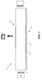
- Fig. 1 is a side view of a elongated illuminator 11 with bottom prism -like structure on the non-view side, a view side 13 and a non-view side 14 (side opposite the view side).
- the light bar also has at least one light input ends 15 and at least one solid state light source 16.
- the prism-like structure 12 may have an included angled features of either constant angle of variable angle to control the amount and relative direction of light.
- the prism-like structure may vary in feature density (shape, size and angle) as a function of the distance from light entering side. While depicted as having two light input side, it may have only one with a optional reflector on the opposite side.
- embodiments of this invention may further comprise other light control elements on either the non-view side 14 as well as the view side 13.
- the functional aspects may include but are not limited to reflection both diffuse and specular, light shaping including collimation, spreading, directional change, and polarization (absorptive, reflective, circular, elliptical and other means),light extraction, optical coupling, light modulating and light filtering.
- These and other functions may be integrated into the elongated illuminator, attached or non-attached in any order or combination (s).
- the light input end may further comprise an antireflection function.
- the elongated illuminator may also have a its sides, and ends finished or polished to a point as to minimize any light extraction that is not intended.
- the light bar and the prism-like features may also be changed in their shape and dimensions and density to provide color mixing and uniformity of illumination.
- Fig. 2 is a further variation of the previous figure.
- Fig 2A is a elongated illuminator with a view side 13 and a non-view side 14.
- a view side surface extraction feature 22 that is continuous in its pitch between extraction features and on the non-view side is a surface pattern (for example dots or other shape) that varies in their size and or density (relative dot area vs.non-dot area).
- the dot pattern may be printed or otherwise deposited or formed on the surface.
- the non-view side may vary in its relative size, density and reflectivity as a function from solid sate light source 16. In order to provide uniform light extraction, the density of the non-view side dots increases towards the center of the elongated illuminator.
- Fig. 2B is also a elongated illuminator with a variable density surface extraction feature 21 on the view side 13 and a variable density printed dot pattern 23 on the side opposite of the view side.
- printed dot pattern may vary in density, size, shape and reflectance. Typically the density of either the extractors or printed dots will be lower near the light input end 15 vs. the center that will have a higher density. The pattern of the dots and or the extractors is adjusted to provide uniform light mixing and illumination. The density will increase along the length of the elongated illuminator the further the light travels from lightsource 16.
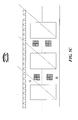
- Fig. 3A is another embodiment of this invention in which an integral elongated illuminator pattern is formed by removing portions of the material from a lightguide plate.
- the integral elongated illuminator could also be molded.
- the interconnected pattern provides additional stiffness to the elongated illuminators as well as an additional pathway for light move between elongated illuminator-like segments. Both a top view and perspective view for embodiment shown in 3A.
- This elongated illuminator may also have a reflector on the opposite end of the light source in those embodiments in which the light source is provided from one end. Such an arrangement provides for the returns of light into the elongated illuminator for extraction towards the view side.
- these and other similar embodiments may have a view side extraction features and or non view side reflective features for example prism-like features, printed dot, reflective surface.
- Fig. 3B is another variation of a ligthbar with connecting integral solid pathway 34.
- Fig. 3C is a top view of a similar light bar to Fig. 3A except that light source 16 and optional reflectors 33 are applied on staggered and opposite ends of the continuous light bar 38. Internal air gap segments 32 helps to provide TIR of the entering light. Although not shown there is a view and non-view side and as described in other figures and embodiments that may comprise features for light extraction and light redirection.
- Fig 3D is a a serpentine like elongated illuminator 39 with solid connecting material 34 and an open air gap 32 to aid in total internal reflection of light from light source 16. Opposing each light source is a reflector.
- Fig. 4 is an end view of a light bar 40 with a tapered air gap 41.
- the tapered airgap provides a means for the spreading of light as it moves towards the view side of the apparatus.
- Fig. 5 is an embodiment of this invention in which a elongated illuminator pattern is formed from a slab of polymer such as PMMA or polycarbonate.
- the primary difference in this embodiment is the integral bridge 53 connecting open spaces air gap 32.
- This embodiment provides a continuous solid surface. While depicted as having the solid surface on top or on the view side, another embodiment could be on the bottom side or on both the top and bottom.
- Surface extraction features can be placed on the view side and or reflective pattern on the opposite side.
- Surface extraction features 22 shown in this figure is a continuous channeled extractor that has been adhered to the elongated illuminator with adhesive layer 52. It should be noted that a surface extraction feature that are individual features with varying size, shape and density may also be used to improve the uniformity of light mixing and illumination.
- Fig. 5C is a elongated illuminator apparatus with internal bridges 53 on both the view and non-view side. Also shown is a multiple array of light sources foe each light channel. While the air gap is surrounded by material on all sides, it may be desirable to form such an apparatus by placing two light bar on top of one another. Each elongated illuminator would be optically coupled by adhesive, melt fusing of the polymer.
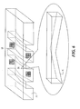
- Fig.6 is a perspective view of an integral array of light bars with connecting bridges and solid elongated illuminator channel or section 34 are tapered from each light input end towards the center. There is also an enlarged side view of one section of the tapered elongated illuminator with an angled (tapered) non-view side 61.
- An air gap 32 provides a means to TIR the light from light source 16 within the width dimension of the integral array of light bars.
- the top side or viewing side provides a continuous pathway for the light to uniformize between light bars.
- the interconnecting continuous pathway furthermore provides added structural strength to the integral array of elongated illuminators.
- Fig.7 is perspective view of a elongated illuminator with a view side slab 71 similar to fig.6 except that it is formed by adhering light bars to a plate light guide plate.
- the bottom portion of the light bar as described previously may have a reflective surface, a prism-like structure, roughen bottom surface, reflective dots or other shape.
- the elongated illuminators may be optically coupled to the top slab by a variety of means such as an adhesive layer 72, melt fusing of the two polymers or other means to minimize light scattering or absorption. Such an arrangement will provide additional stiffness to keep the light is a parallel plane to the viewer.
- Fig. 8 is a side view of a tapered light bar with a tapered from each light input end 15 with mixing section 81 depicted by the dotted line and the light input end of the elongated illuminator.
- Elongated illuminator is tapered from each light input end and has a compounded tapered from each end.
- the compound taper has two angled segments 83 with a slope A and 85 with slope B that vary from the mixing section to the center of the elongated illuminator.
- Fig. 9 is a side view of a tapered elongated illuminator 90 with a mixing section and with a prism-like structure on the non-view side that helps to redirect light to the view side surface with either constant or variable density as a function from the distance from the light input end. It should be noted that the view side surface may also have extraction or otherwise light redirecting features on or adhered to the surface.
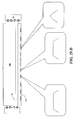
- Fig. 10A is a side view another embodiment of a light bar and Fig. 10B is a top view of the elongated illuminator looking at the bottom side of the light bar and a series of reflective dots.
- the density of the reflective dots 101 vary from the light input end and mixing section 81 to the center of the elongated illuminator.
- the reflective dots may be printed or otherwise from/placed on the non-view side surface.
- the reflective dots may be either specular or diffusive and they may be metallic-like or white.
- the size and shape may also be varied as a function of the distance from the light input end as well as the mixing section in order to achieve uniform light extraction and illumination from one end of the bar to the other.
- a similar embodiment anticipated would provide only one input light source, a mixing section and one taper and a reflector at the end.
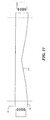
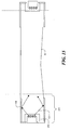
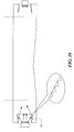
- Fig. 11 is a elongated illuminator with a curved radius taper 111 extending from the end of each light mixing section to the center. Having a constant radius is desire to provide uniform light extraction. Having a smooth transition along the length of the elongated illuminator is desirable for uniform extraction and preventing unwanted scattering of light in areas in which it is not desired.
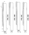
- Fig. 12A is a elongated illuminator arrangement with a flat light input end 15 on at least one end, at least light source 16, a light extraction feature on the view side of the elongated illuminator 22 and a means of optically coupling the features with adhesive layer 52 and at optional reflective means 121 on the non-view side of the elongated illuminator.
- the reflective means 121 may be continuous or variable in its reflective properties to aid in uniform light illumination along the length of the elongated illuminator.
- Fig. 12A is a elongated illuminator arrangement with a flat light input end 15 on at least one end, at least light source 16, a light extraction feature on the view side of the elongated illuminator 22 and a means of optically coupling the features with adhesive layer 52 and at optional reflective means
- Fig. 12B is a similar elongated illuminator arrangement but it has at least one tapered light input ends. While the taper is shown in one direction, other embodiments may have the taper angled in the other direction. Furthermore the angle may comprise more than one direction.
- Fig. 12C is a further extension of the useful elongated illuminator of this invention where a specularly reflective surface 123 is provided on the end opposite of the light source.
- Fig. 12D provides a scattering reflector 124 on the end opposite from the light source.
- Fig. 14A is a elongated illuminator with a descending (top to bottom) tapered light input surface 141 that accepts light from light source 16. Since 16 may be an LED source, it output is substantially hemispherical so it may be desirable to provide a reflective surface that helps to redirect light into the elongated illuminator at a critical TIR angle. The reflective surface may be specular or diffusive. In another embodiment surface 142 may comprise a structured that aids in light redirection. While the above figures are shown as having both ends the same design, it may be desirable to have different light input ends.
- Fig. 14B is another elongated illuminator with a tapered light input surface 143 and light source 16.
- the light projected is hemispherical and not all the light being put out will enter the light bar at the critical TIR angle and therefore be lost to the surrounding environment.
- a means to redirect light may include a curved surface 144 that provides specular light reflection, a surface that provides diffuse reflection or a featured surface such as a prism.
- Fig.15 has a recess light entry area with optional antireflective light input surface 151 that enhances the amount of light entering the light bar.
- the antireflective surface may be on one or all sides of the recess area 152.
- the initial section 153 is a light mixing section and typically extends from the light input surface to the start of the taper. It should be noted that some additional mixing may occur throughout the length of the light bar and not exclusively within the mixing section.
- Additionally reflective surfaces 154 may be provides near and around the light input area of the elongated illuminator to help redirect light into the bar at a TIR angle that provides good mixing and uniform illumination.
- the tapered section helps to provide more uniform light extraction towards the view side.
- Such a light bar arrangement may also have light redirecting features such as but not limited to prism-like features, roughen surface, reflective surface. Such redirecting features may vary in density as a function of their distance from the light input end.
- the taper or tapers form a compound tapered light bar. It should be noted in this figures and others within this invention are not limited by the general ratio or relative dimensions as shown in this side view cross section. In reality the length dimension is many time loner than the width dimension. The width dimension is enlarged in order to provide room for see the intended detail.
- Fig. 16 is a elongated illuminator with recessed light input region with a tapered light input sides on the top and bottom of the recessed light input region.
- the tapered entry surface may be a reflective surface or prism-like feature to redirect the light to a critical TIR angle within the elongated illuminator. It should be noted that such a light input recess area may also have an anti reflective surface on one or more of the light input surface to help maximize the light entering the elongated illuminator.
- Fig. 17A is Fig. 17A is trapezoidal wedge elongated illuminator configuration is a wider view angle side than non-view angle side. While it is shown with a an angled bottom, it should be noted that a smooth radius may be used be used to allow to spread out laterally as it approaches the exit (view side) side of the elongated illuminator. This is useful because the light uniformity is provided over a wider footprint.
- Fig. 17B is another design of a light bar 173 that provides a wider inlet for light towards the non-view side and the side gradual taper inward to help intensify or concentrate the light. Such a configuration provides improved light mixing.
- Both Fig. 17A and B may have light mixing sections adjoining the light input entry surface. Additionally these configuration may be tapered towards the center, may have printed dots or other configurations to redirect light towards the view side.
- Fig. 18A is perspective view of a circular elongated illuminator 181 with initial mixing section 182and a tapered elongated section 183 with a reflector 184 at the opposite end of the light input end 15.
- Fig. 18B is a perspective view of a circular elongated illuminator with a flat view side surface 185 that may additionally be roughen or comprise a light extraction feature.
- the circular elongated illuminator provides a means to minimize trapping light in the corners.
- the flat view side portion is desirable for adhering light extraction features and providing a broader cross section to direct light towards the viewer. As previously discussed the light extraction features may vary in shape and or density.
- Fig. 18C is a perspective view of a elongated illuminator but has at least two flattened surfaces (185 is the view side and 186 is the non-view side).
- the bottom or non-view side may be tapered from each light input end towards the center or if the elongated illuminator is only lit from one end, it may be tapered from the light input end towards the opposite end reflector.
- the non-view flattened surface may be further roughened to help mixing and scatter light or it may be printed with reflective dots and or other shapes.
- FIG. 18D is a perspective view of another elongated illuminator embodiment of this invention with a multi-facets 187. While this figure shows 8 sides other configurations with more or less may be useful.
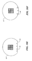
- Fig. 18E and 18F are end views of other embodiments for elongated illuminators that have good light mixing and good length light uniformity.
- circular elongated illuminator 181 has a non-view side flat surface that has a series of light scattering features 188 that have been recessed into the elongated illuminator.
- the features shown are conical in shape in that they are wider on the surface of the elongated illuminator as opposed the part that is on the interior of the elongated illuminator.
- the scattering feature may also trapezoidal with a flat surface as opposed to a point on the interior.
- the number, density, shape, size, depth of the scattering feature may vary from the light input end to the center for a elongated illuminator that is lit from both ends or may vary from the light input side to the end for a elongated illuminator that in lit only from one end.
- the indents may be replaced with reflective dots or other patterns or even a continuous reflector is the elongated illuminators are also tapered.
- the elongated illuminator does not have a flat bottom surface but the light scattering features 189 are made directly into the arc of the elongated illuminator.
- the indents may vary in their size, density, shape, and or depth as a function of the distance from the light input end. It should also be noted that a combination of indents on a flay and on part of the arc may also be useful.
- Fig. 19A is a perspective view of a circular elongated illuminator with distribution cap 191.
- the distribution cap helps to spread light over a wider area.
- Fig. 19B is an end cross sectional view of a elongated illuminator with a lens-like surface structure 192 that can help focus light.
- Fig. 19C is a elongated illuminator with a convex surface 193 on the view side. The advantage of this type elongated illuminator is that it helps redirect light.
- Fig. 19D is an end cross section of a elongated illuminator with a view side flare 194 that helps to distribute light in a wider cross section.
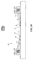
- Fig. 20 is an end cross sectional view of a backlight 200 with an array of elongated illuminators with a means of extracting light on more than one surface 201 and region between the elongated illuminators 202 that provides redirecting the light.
- the region between the elongated illuminators may be specularly reflective, diffusely reflective, prismatic or otherwise featured.
- the region between the elongated illuminators may vary in its redirecting properties in order to provide uniform color temperature and illumination. In those embodiments with a feature the shape, size and or density may be varied.
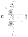
- Fig. 21 is a cross sectional view of another means of redirecting and spreading light in a backlight array 210.
- Elongated illuminators have more than light extraction side 201 are provide with controlled side leakage in conjunction with a curved reflector region 211 between the backlights. It should be noted that this and other figures are not drawn to scale nor should they be interpreted as being near relative scale.
- the curved region between light bars is shaped to provide redirecting of the light towards the view side of the in a manner to provide uniform light illumination.
- the light extraction means on the light bars may be varied along their length to provide uniform lighting. Typically the density of the extraction feature is less near the light source and higher the further the distance from the light source.
- This embodiment may further have a light source on each end or on one end with a reflector on the opposite end of the elongated illuminator.
- the curved portion of the region between elongated illuminators may be specularly or diffusely reflective. This region may also have also be roughened or patterned with a redirecting feature.
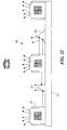
- Fig. 22 is a backlight array 220 with elongated illuminators that have multiple sides with extraction means 201.
- a shaped reflector 221 and or radius reflector 222 that provides a means to redirect light towards the view side. While only one reflector is shown between a set of elongated illuminators, there may be more than one and they may vary in shape and size. These reflector features while shown to be large in relation to the elongated illuminator may be much smaller or micro in scale.
- the base 223 may also be reflective.
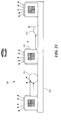
- Fig. 23 is a backlight array 230 with elongated illuminators that have multiple sides with extraction means 201.
- a shaped reflector 231 and or 232 that provides a means to redirect light towards the view side. While only one reflector is shown between a set of elongated illuminators, there may be more than one and they may vary in shape and size. These reflector features while shown to be large in relation to the elongated illuminator may be much smaller or micro in scale.
- the base 223 may also be reflective.
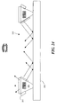
- Fig. 24 is another backlight array with trapezoidal shaped light bars 241 with light extraction means 201 on more than one side. As shown the light extraction feature may be on all or part of the side surface of the elongated illuminator.
- the base 223 may be reflective to provide light redirection and light distribution.
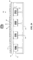
- Fig. 25A and 25B is a side cross section of a elongated illuminator with view side 13 and non-view side 14, light source 16 and surface extraction means 22 for light extraction. Additional there is a series of other functional films or layers (can be separate or integral) that can be used in combination with the elongated illuminator and view side extraction means. It should be noted that while not shown, the elongated illuminator may be of other size, shape and design as shown in previous figures, the non-view side may also have added functionality to provide light redirection to help provide uniform light mixing and illumination. While they are shown with a space and above the light extraction means, it should be noted that they be on top of (in contact with) or optically coupled with the light extraction means.
- the functionality may be by itself or in combination one or more functionalities.
- the added functionality may include but is not limited to polarization fibers 251, lenticular film 252, cylinder film 253, fresnel lens film 254, bulk diffuser 255 ( may be voided and or filled polymer film), beaded diffuser 256, light enhancing film 257, reflective polarization film 258.
- These and other functionality may in as a single film or layer and one or more functionality may be combined in a single film.
- the backlight may also include light modulation, light spreading, light columation, light absorbing.
- Fig. 26 is an end view of a backlight array 260 with elongated illuminator 261 with light source.
- the light bars are adhered to the bottom of transparent plate 263 with transparent adhesive layer 262. Additionally there is a second adhesive layer 264 and light extraction features 22 on the view side of the array.
- the elongated illuminators also have a prismatic feature 265 on the non-view side to aid in the extraction of light.
- an optional standoff 266 that provides support to the elongated illuminator and transparent plate. The standoffs help to prevent sagging and to keep the various part flat and at a uniform distance from other parts of an LCD display such as LCD array, polarizer and view side display (not shown).
- the elongated illuminators are enclosed in a case or box 267 that has reflective surfaces.
- the light bars may vary in the shape, size and side profile including but not limited to tapers, light mix sections.
- the light source may also include means to maximize the coupling of light into the elongated illuminator including but not limited to providing a means to capture and redirect light into the bar at an appropriate TIR angle.
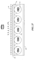
- Fig. 27 is an end cross section of a backlight array with curved elongated illuminators 271.
- the top portion of the elongated illuminators have been optically coupled over a large arc of the circle so as to provide a light distribution pathway 191 for the light to spread to regions between the elongated illuminators towards the extraction film.
- the light distribution pathway or cap on the view side of the elongated illuminators is optically coupled to a transparent plate 263. Curved type elongated illuminators are useful because the curved profile does not trap light in regions that are difficult to extract.
- Light source 16 is couples into one or both ends of elongated illuminator 271. If only on one end, there may be an optional mirror reflector on the side opposite to the light source.
- the light distribution pathway or cap on the view side of the elongated illuminators may be molded as an integral part of the transparent plate 263 and the elongated illuminators adhered to the cap. Such a configuration would be useful in eliminating a needed for a linear fresnel.
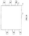
- Fig. 28 is a top view of a lightguide plate 281 with light source 16 and mixing tabs 283 and reflective surface 282.
- Mixing tabs 283 provide for a means of mixing the individual colors from the lights LED light source to provide uniform white light prior to entering the lightguide plate.
- the mixing tabs have a light input surface that may be designed to capture as much light as possible from the light source. They may have an antireflective coating, and they may be contoured to capture more of the hemispherical light output from the LED's. There may also be optional side reflectors that cover part of the LED to help capture and redirect light into the lightguide plate.
- Opposite of the mixing tabs is a reflective surface to provide a means to maximize the light output of the lightguide plate.
- the reflectors may be a white scattering material or it may be specturally reflective.
- the reflector may have a smooth mirror-like surface or it may be roughen to aid in scattering.
- the lightguide plate may be a variety of configuration.
- the lightguide may have a featured on the non-view side to help in the redirection of light towards the view side.
- the featured surface may be a roughend surface, prisms, printed dots or other such means. Such features may be varied in their size, shape and density in order to provide uniform luminance across the length and width of the lightguide plate.
- the profile of the light guide may be uniform or tapered. It should be noted that while the above figure shows light input from both ends of the lightguide, other embodiments may have light input from only one end or from more than two ends.
- Fig. 29A, 29B and 29C are side view cross sections elongated illuminator 290 with a series of holes or indents 291, 292 and 293 that are formed in the non-view side.
- the elongated illuminators may be lit from one or both ends by light source 16. If lit from one end only, there may be a reflector on the end opposite the light source.
- the holes or indents may be any shape or size or may vary in shape and or size as a function of distance from the light source. In some embodiments the holes have the same relative size in the width and length dimensions.
- the features in general may be in the 1-300 micron size range in their depth although larger or slightly smaller may be desirable.
- the features are useful in scattering light and redirecting it towards the view side of the elongated illuminator.
- the elongated illuminator may be flat, tapered, round or other shape or compound shape.
- the holes or indents may be drilled, or replicated in the surface during molding or casting. For shallow holes it may be possible to use a laser. Other techniques may include the use of photo-patterning with a photo-resist and chemical etching.
- the indents and holes may be mechanically embossed with the assistance of heat and or pressure. As the holes are made deeper there may be problems with achieving good replication beyond 50-100 microns. Providing holes or indents with side wall with a rough surface may further enhance light redirection.
- the spacing, density , size and shape may be varied to provide uniform lighting along the length of the elongated illuminator. While only a side view is shown in these figures, the side dimension may also vary in the number of features.
- the elongated illuminator may also provides means to more efficiently couple the light source into the elongated illuminator. These may include but is not limited to indented or recessed ends, reflectors, embedding the light source in a flexible media such as an adhesive, providing a lens to shape, collimate or otherwise direct the light as it exits the light source.
- Such a means helps to setup a TIR angle into the elongated illuminator to optimize the amount of light entering vs. the amount of light that exits the light source. Additionally the holes and indents as well as the other means of optimization the light bar may be applied to and used in a lightguide plate as well as a light bar or elongated illuminator
- Fig. 30A is a elongated illuminator arrangement with at least one prism shape light input end 15 on at lest one end, at least light source 16, a light extraction feature on the view side of the elongated illuminator 22 and a means of optically coupling the features with adhesive layer 52 and at optional reflective means 121 on the non-view side of the elongated illuminator.
- the reflective means 121 may be continuous or variable in its reflective properties to aid in uniform light illumination along the length of the elongated illuminator.
- Fig. 30B is a similar elongated illuminator arrangement but the prism on the prism shape light input ends covers the entire light input end.
- Fig. 1C is a further extension of the useful elongated illuminator of this invention where there are multiple prisms on the light input ends.
- Fig. 1D is a similar elongated illuminator arrangement but the prisms on the prism shape light input ends covers the entire light input end.
- Fig. 31A is a side view cross section of a elongated illuminator 31 with a series of optical fibers 32. Each optical fiber has light extraction features 33 at different distance from light source.
- Fig. 31B is a side view cross section of a elongated illuminator 31 with a series of optical fibers 32. Each optical fiber has different length.
- One embodiment uses an acrylic light pipe as an elongated illuminator, nominally 1 ⁇ 4 in. square in cross section.
- the light pipe is highly transparent and has an optical finish on all sides and ends of less than 25 nm.
- a larger acrylic square bar (0.25" x 0.25" x 6 feet) was sawed into 14 inch segments and the ends were polished on a lathed.
- a piece of light extraction film was attached to one surface of elongated illuminator with UV epoxy, dispensed using a syringe to form a uniform narrow epoxy bead down the length of elongated illuminator.
- the adhesive was then cured under a UV lamp.
- Multi-die RGB LEDs are mounted in close proximity to the light channel. These multi-die LEDS consist of 1 red, 1 blue and 2 green die in a single package (OSRAM OSTAR Projection devices, type LE ATB A2A, from OSRAM, Inc.) These devices can be individually turned on, with the brightness of each die controlled by a separate current source.
- OSRAM OSTAR Projection devices type LE ATB A2A, from OSRAM, Inc.
- FIG. 10 Another embodiment of an elongated illuminator is shown in lengthwise cross-section in Figure 10 , not to scale. A series of printed white dots was applied to the non-view side of a tapered elongated illuminator using a micro-tip dispenser.
- the light output was evaluated along the length of the bar with and without the addition of a light extraction film and also a prismatic turning film. In general it was found that the printed dot-like features provided good light uniformity. The light extraction film provided little additional benefit when used in combination with the printed dots and the turning film was found to have a narrow viewing angle.
- a collimating linear Fresnel film with a focal length of approximately 2.5 inches) was placed over top of light channel with an air gap approximately equal to the focal length of the film.
- a series of photos demonstrated high brightness with good spatial uniformity. LEDs were lit individually to produce R, G, B illumination and then mixed together to form a well-mixed white LED light.
- the color uniformity of a light pipe configured as light channel according to the present invention was compared to the color uniformity of a light guide plate (LGP) for similar solid-state light sources.
- the light pipe was formed from PMMA and had a 6mm square cross section and 245 mm length.
- a light extraction film was adhered to the top side of the light pipe.
- the light extraction film had prismatic features partly embedded into a layer of optical clear adhesive that forms regions of polymer next to regions of air.
- the adhesive (approximately 10 microns thick) was coated onto a sheet of polyester film. The polyester film was then adhered to the top side of the light pipe using an optically clear adhesive.
- An array of LEDs was position on each end of the elongated illuminator. The output light was measured as it exited the elongated illuminator. A point approximately midway between the LEDs and near the widthwise center of the elongated illuminator (approximately 3mm from an edge) was measured as. A second point near the edge was selected and compared in color uniformity to the center point.
- a light guide plate of the same material, thickness and length was selected.
- the width of the LGP was several times wider than the light pipe.
- the same type of light extraction film was applied to the LGP in a similar manner as described for the light pipe.
- the LGP used the same LED light sources on each end. A point midway between the LEDs was selected and also measured .
- the elongated illuminator visually had better brightness and better uniformity over a comparable length of the light guide plate.
Landscapes
- Physics & Mathematics (AREA)
- General Physics & Mathematics (AREA)
- Optics & Photonics (AREA)
- Nonlinear Science (AREA)
- Mathematical Physics (AREA)
- Chemical & Material Sciences (AREA)
- Crystallography & Structural Chemistry (AREA)
- Planar Illumination Modules (AREA)
- Non-Portable Lighting Devices Or Systems Thereof (AREA)
Applications Claiming Priority (1)
| Application Number | Priority Date | Filing Date | Title |
|---|---|---|---|
| US11/749,171 US7780330B2 (en) | 2007-05-16 | 2007-05-16 | Elongated illuminators configuration for LCD displays |
Publications (1)
| Publication Number | Publication Date |
|---|---|
| EP1992870A2 true EP1992870A2 (fr) | 2008-11-19 |
Family
ID=39645267
Family Applications (1)
| Application Number | Title | Priority Date | Filing Date |
|---|---|---|---|
| EP08156311A Withdrawn EP1992870A2 (fr) | 2007-05-16 | 2008-05-15 | Configuration d'illuminateurs allongés pour écrans LCD |
Country Status (6)
| Country | Link |
|---|---|
| US (1) | US7780330B2 (fr) |
| EP (1) | EP1992870A2 (fr) |
| JP (1) | JP2009043706A (fr) |
| KR (1) | KR101521477B1 (fr) |
| CN (1) | CN101349400B (fr) |
| TW (1) | TWI375085B (fr) |
Cited By (12)
| Publication number | Priority date | Publication date | Assignee | Title |
|---|---|---|---|---|
| JP2010192269A (ja) * | 2009-02-19 | 2010-09-02 | Sharp Corp | 光源モジュール |
| WO2010102777A1 (fr) * | 2009-03-10 | 2010-09-16 | Gm Global Technology Operations, Inc. | Dispositif d'affichage pour un véhicule à moteur et procédé de fabrication du dispositif d'affichage |
| EP2317352A1 (fr) * | 2009-11-03 | 2011-05-04 | 3M Innovative Properties Company | Guide lumineux latéral et dispositif d'éclairage |
| EP2530375A1 (fr) * | 2011-05-31 | 2012-12-05 | LG Innotek Co., Ltd. | Structure d'un guide de lumière à illumination latérale pour un rétroéclairage |
| EP2258976A4 (fr) * | 2008-05-30 | 2014-01-15 | Sharp Kk | Dispositif d'éclairage, dispositif d'affichage et plaque de guidage de lumière |
| TWI455082B (zh) * | 2011-06-08 | 2014-10-01 | Innolux Corp | 顯示器 |
| US8870432B2 (en) | 2011-10-14 | 2014-10-28 | Au Optronics Corporation | Sheetless backlight module, a light guide plate for the sheetless backlight and manufacturing method thereof |
| WO2017214475A1 (fr) * | 2016-06-10 | 2017-12-14 | Corning Incorporated | Articles en verre comprenant des éléments d'extraction de lumière |
| TWI679454B (zh) * | 2018-08-06 | 2019-12-11 | 大陸商瑞儀(廣州)光電子器件有限公司 | 導光板、背光模組及顯示裝置 |
| WO2020221641A1 (fr) * | 2019-04-29 | 2020-11-05 | Signify Holding B.V. | Dispositif électroluminescent |
| WO2021110456A1 (fr) * | 2019-12-03 | 2021-06-10 | Signify Holding B.V. | Combinateur de faisceau laser compact avec réflecteur à micro-prisme |
| WO2022238111A1 (fr) * | 2021-05-12 | 2022-11-17 | Volkswagen Aktiengesellschaft | Dispositif d'éclairage pour l'intérieur d'un véhicule automobile |
Families Citing this family (117)
| Publication number | Priority date | Publication date | Assignee | Title |
|---|---|---|---|---|
| US7991257B1 (en) * | 2007-05-16 | 2011-08-02 | Fusion Optix, Inc. | Method of manufacturing an optical composite |
| JP2008300115A (ja) * | 2007-05-30 | 2008-12-11 | Olympus Corp | 照明装置および画像投影表示装置 |
| US8721149B2 (en) * | 2008-01-30 | 2014-05-13 | Qualcomm Mems Technologies, Inc. | Illumination device having a tapered light guide |
| JP4607225B2 (ja) * | 2008-07-08 | 2011-01-05 | シャープ株式会社 | 光源モジュール、液晶表示装置および照明装置 |
| JP4565037B2 (ja) * | 2008-09-12 | 2010-10-20 | シャープ株式会社 | 光源モジュールおよびそれを備えた光源装置と電子機器 |
| JP5275009B2 (ja) * | 2008-12-19 | 2013-08-28 | ローム株式会社 | 導光体、線状光源、および、画像読取装置 |
| US20100220497A1 (en) * | 2009-01-14 | 2010-09-02 | Ngai Peter Y Y | Luminaire having floating luminous light source |
| US8905610B2 (en) | 2009-01-26 | 2014-12-09 | Flex Lighting Ii, Llc | Light emitting device comprising a lightguide film |
| TW201040433A (en) * | 2009-05-14 | 2010-11-16 | Young Lighting Technology Corp | Illumination apparatus |
| US8297818B2 (en) * | 2009-06-11 | 2012-10-30 | Rambus International Ltd. | Optical system with reflectors and light pipes |
| JP5184445B2 (ja) * | 2009-06-19 | 2013-04-17 | シャープ株式会社 | 光源モジュール、及びそれを備えた電子機器 |
| WO2010147219A1 (fr) * | 2009-06-19 | 2010-12-23 | シャープ株式会社 | Module de source de lumière et équipement électronique le comportant |
| CN102089573A (zh) | 2009-09-30 | 2011-06-08 | 夏普株式会社 | 光源组件及具备该光源组件的电子设备 |
| BRPI1001233A2 (pt) | 2009-10-07 | 2016-02-10 | Sharp Kk | "módulo de fonte de luz e aparelho eletrônico que inclui o mesmo" |
| JP4560579B1 (ja) | 2009-10-09 | 2010-10-13 | シャープ株式会社 | 面光源装置 |
| TWI459088B (zh) * | 2009-11-27 | 2014-11-01 | Au Optronics Corp | 具導光板稜柱結構的背光模組及其製造方法 |
| US20120212975A1 (en) * | 2009-12-22 | 2012-08-23 | Sharp Kabushiki Kaisha | Light guide unit, illumination device and display device |
| KR101607508B1 (ko) | 2010-01-08 | 2016-03-31 | 삼성디스플레이 주식회사 | 터치 모듈, 이를 갖는 표시 장치 및 터치 모듈의 터치 위치 검출 방법 |
| TWI386591B (zh) * | 2010-01-15 | 2013-02-21 | Young Lighting Technology Corp | 光源裝置 |
| WO2011109866A1 (fr) * | 2010-03-08 | 2011-09-15 | Associated Controls (Australia) Pty Ltd | Appareil d'éclairage avec un guide d'ondes et une matrice réfléchissante |
| KR101749266B1 (ko) * | 2010-03-24 | 2017-07-04 | 삼성디스플레이 주식회사 | 터치감지 표시 장치 및 컴퓨터용 기록매체 |
| US9651729B2 (en) | 2010-04-16 | 2017-05-16 | Flex Lighting Ii, Llc | Reflective display comprising a frontlight with extraction features and a light redirecting optical element |
| US8100574B2 (en) * | 2010-05-20 | 2012-01-24 | Young Lighting Technology Corporation | Light module |
| KR101250374B1 (ko) * | 2010-09-09 | 2013-04-05 | 엘지이노텍 주식회사 | Sag 조절 패턴이 형성된 백라이트 유닛 |
| JP2012069324A (ja) * | 2010-09-22 | 2012-04-05 | Konica Minolta Opto Inc | 光源ユニット |
| GB2484713A (en) | 2010-10-21 | 2012-04-25 | Optovate Ltd | Illumination apparatus |
| US20120113619A1 (en) * | 2010-11-04 | 2012-05-10 | Au Optronics Corporation | Light source and backlight module having the same |
| CA2829388C (fr) * | 2011-03-09 | 2018-09-25 | Flex Lighting Ii, Llc | Dispositif electroluminescent dote d'un profil de flux lumineux reglable |
| CN102156321A (zh) * | 2011-05-06 | 2011-08-17 | 成都奔流标识制作有限责任公司 | 一种广告灯箱用导光板及其制造方法 |
| TWM417571U (en) * | 2011-06-29 | 2011-12-01 | Coretronic Corp | Backlight module |
| US20130063973A1 (en) * | 2011-09-09 | 2013-03-14 | Peter H. Mahowald | Lighting fixtures having observable illuminated speckled pattern |
| US20130088889A1 (en) * | 2011-10-10 | 2013-04-11 | Samsung Display Co., Ltd. | Backlight unit and display device having the same |
| US8764264B2 (en) | 2011-10-11 | 2014-07-01 | GE Lighting Solutions, LLC | Edge-lit luminaire |
| TWI451312B (zh) * | 2011-12-19 | 2014-09-01 | Pixart Imaging Inc | 光學觸控裝置及其光源組件 |
| JP6202828B2 (ja) * | 2012-02-17 | 2017-09-27 | 学校法人慶應義塾 | 液晶表示装置 |
| WO2014020844A1 (fr) * | 2012-07-31 | 2014-02-06 | 三菱電機株式会社 | Appareil de source lumineuse surfacique et appareil d'affichage à cristaux liquides |
| DE102012213845B4 (de) * | 2012-08-03 | 2015-05-28 | Automotive Lighting Reutlingen Gmbh | Lichtleitelement und Lichtmodul |
| FR2998942B1 (fr) * | 2012-11-30 | 2018-08-17 | Valeo Vision | Dispositif d'eclairage et/ou de signalisation, notamment pour vehicule automobile |
| US9133989B2 (en) * | 2012-12-15 | 2015-09-15 | Lumenetix, Inc. | Mechanical attachment system for linear light modules |
| DE102013000336A1 (de) * | 2013-01-11 | 2014-07-17 | Werma Holding Gmbh + Co. Kg | "Betriebszustandswarnleuchtvorrichtung" |
| US11009646B2 (en) | 2013-03-12 | 2021-05-18 | Azumo, Inc. | Film-based lightguide with interior light directing edges in a light mixing region |
| US20140268879A1 (en) * | 2013-03-14 | 2014-09-18 | Panasonic Corporation | Transparent waveguide diffuser for lighting and methods of manufacturing transparent waveguide diffuser |
| US10209429B2 (en) * | 2013-03-15 | 2019-02-19 | Cree, Inc. | Luminaire with selectable luminous intensity pattern |
| WO2014155227A1 (fr) * | 2013-03-29 | 2014-10-02 | Koninklijke Philips N.V. | Dispositif électroluminescent comprenant un convertisseur de longueur d'onde |
| CN104238186A (zh) | 2013-06-20 | 2014-12-24 | 扬升照明股份有限公司 | 背光模块 |
| CN105556202A (zh) * | 2013-09-10 | 2016-05-04 | 飞利浦照明控股有限公司 | 发光设备 |
| CN104456425B (zh) * | 2013-09-13 | 2017-09-19 | 扬升照明股份有限公司 | 面光源 |
| US10012779B2 (en) * | 2013-10-25 | 2018-07-03 | Philips Lighting Holding B.V. | Light emitting device |
| JP2015103362A (ja) * | 2013-11-25 | 2015-06-04 | スタンレー電気株式会社 | 車両用灯具 |
| WO2016118107A1 (fr) * | 2015-01-19 | 2016-07-28 | Leia Inc. | Rétro-éclairage basé sur un réseau unidirectionnel employant un îlot réfléchissant |
| US10061071B2 (en) * | 2015-01-22 | 2018-08-28 | Philips Lighting Holding B.V. | Panel luminaire |
| DE202015104088U1 (de) * | 2015-08-05 | 2016-11-09 | Zumtobel Lighting Gmbh | Leuchtenoptik sowie Leuchte aufweisend die Leuchtenoptik |
| CN108351951B (zh) | 2015-10-26 | 2023-02-07 | 瑞尔D斯帕克有限责任公司 | 智能隐私系统、设备及其方法 |
| CA3015210A1 (fr) | 2016-02-26 | 2017-08-31 | Magic Leap, Inc. | Systeme d'affichage ayant une pluralite de conducteurs de lumiere pour une pluralite d'emetteurs de lumiere |
| CN105700234B (zh) * | 2016-04-06 | 2019-08-20 | 武汉华星光电技术有限公司 | 背光模组及液晶显示器 |
| US11719882B2 (en) | 2016-05-06 | 2023-08-08 | Ideal Industries Lighting Llc | Waveguide-based light sources with dynamic beam shaping |
| US10416377B2 (en) | 2016-05-06 | 2019-09-17 | Cree, Inc. | Luminaire with controllable light emission |
| US11079619B2 (en) | 2016-05-19 | 2021-08-03 | Reald Spark, Llc | Wide angle imaging directional backlights |
| US20180046028A1 (en) * | 2016-08-12 | 2018-02-15 | Innolux Corporation | Display device |
| DE102016218712A1 (de) * | 2016-09-28 | 2018-03-29 | Zumtobel Lighting Gmbh | Optisches System für eine Leuchte, sowie Leuchte |
| DE102016118884A1 (de) * | 2016-10-05 | 2018-04-05 | Temicon Gmbh | Lichtumlenkvorrichtung, Beleuchtungseinrichtung und Verwendung |
| US11022745B2 (en) * | 2016-12-29 | 2021-06-01 | Corning Incorporated | Microstructured and patterned light guide plates and devices comprising the same |
| US10126575B1 (en) | 2017-05-08 | 2018-11-13 | Reald Spark, Llc | Optical stack for privacy display |
| EP3622342A4 (fr) | 2017-05-08 | 2021-02-17 | RealD Spark, LLC | Empilement optique pour affichage directionnel |
| CN110809732B (zh) | 2017-05-08 | 2025-01-10 | 瑞尔D斯帕克有限责任公司 | 用于成像定向背光源的光学叠堆 |
| US10364948B2 (en) * | 2017-05-10 | 2019-07-30 | Ideal Industries Lighting Llc | Optical waveguides and luminaires having a waveguide with extraction features and reflective material having openings disposed thereon |
| US10241253B2 (en) * | 2017-05-11 | 2019-03-26 | Glo Ab | Light bar containing symmetric LED placement and method of making thereof |
| TWI878209B (zh) | 2017-09-15 | 2025-04-01 | 美商瑞爾D斯帕克有限責任公司 | 顯示裝置及應用於顯示裝置的視角控制光學元件 |
| US10948648B2 (en) | 2017-09-29 | 2021-03-16 | Reald Spark, Llc | Backlights having stacked waveguide and optical components with different coefficients of friction |
| GB201718307D0 (en) | 2017-11-05 | 2017-12-20 | Optovate Ltd | Display apparatus |
| US11070791B2 (en) | 2017-11-06 | 2021-07-20 | Reald Spark, Llc | Privacy display apparatus |
| GB201800574D0 (en) | 2018-01-14 | 2018-02-28 | Optovate Ltd | Illumination apparatus |
| EP3743766B1 (fr) | 2018-01-25 | 2026-02-11 | RealD Spark, LLC | Écran tactile pour affichage de confidentialité |
| CN115718382A (zh) | 2018-01-25 | 2023-02-28 | 瑞尔D斯帕克有限责任公司 | 用于防窥显示装置的反射式光学堆叠物 |
| US11003015B1 (en) * | 2018-03-05 | 2021-05-11 | Apple Inc. | Electronic device with a light guiding layer |
| US10935714B2 (en) | 2018-03-22 | 2021-03-02 | Reald Spark, Llc | Optical waveguide for directional backlight |
| GB201807747D0 (en) | 2018-05-13 | 2018-06-27 | Optovate Ltd | Colour micro-LED display apparatus |
| US10955715B2 (en) | 2018-06-29 | 2021-03-23 | Reald Spark, Llc | Optical stack for privacy display |
| US11073735B2 (en) | 2018-07-18 | 2021-07-27 | Reald Spark, Llc | Optical stack for switchable directional display |
| CN108897171B (zh) * | 2018-08-09 | 2021-03-12 | 京东方科技集团股份有限公司 | 背光模组和显示装置 |
| WO2020047340A1 (fr) | 2018-08-30 | 2020-03-05 | Flex Lighting Ii, Llc | Éclairage frontal sur film comprenant un film de diffusion à angle variable |
| ES2973155T3 (es) * | 2018-09-17 | 2024-06-18 | Lmpg Inc | Guías de luz en forma de cuña para luminarias y conjuntos de luminarias que las incorporan |
| EP3853645B1 (fr) | 2018-09-23 | 2023-09-13 | LMPG Inc. | Luminaire |
| WO2020072643A1 (fr) | 2018-10-03 | 2020-04-09 | Reald Spark, Llc | Appareil de commande d'affichage de confidentialité |
| WO2020092160A1 (fr) | 2018-10-31 | 2020-05-07 | Leia Inc. | Rétroéclairage à vues multiples, unité d'affichage, et procédé comportant des éléments de masque optique |
| CN113167953B (zh) | 2018-11-07 | 2023-10-24 | 瑞尔D斯帕克有限责任公司 | 定向显示设备 |
| CN113348404B (zh) | 2018-12-08 | 2023-06-30 | 镭亚股份有限公司 | 采用定向光源和水平漫射器的静态多视图显示器和方法 |
| CN113678034B (zh) | 2018-12-11 | 2024-03-19 | 阿祖莫公司 | 使用基于薄膜的光导和漫反射型剥离衬制造显示器的方法 |
| CN113678035B (zh) * | 2019-01-03 | 2024-10-18 | 阿祖莫公司 | 包括产生多个照明峰值的光导和光转向膜的反射型显示器 |
| US11287677B2 (en) | 2019-01-07 | 2022-03-29 | Reald Spark, Llc | Optical stack for privacy display |
| WO2020146668A1 (fr) | 2019-01-09 | 2020-07-16 | Flex Lighting Ii, Llc | Affichage réfléchissant comprenant des guides de lumière de couplage pliés à différents angles de pliage |
| US11333895B1 (en) | 2019-01-11 | 2022-05-17 | Facebook Technologies, Llc | Systems and methods for structured light projector operational safety |
| US11029566B2 (en) | 2019-02-12 | 2021-06-08 | Reald Spark, Llc | Diffuser for privacy display |
| TWI912252B (zh) | 2019-07-02 | 2026-01-21 | 美商瑞爾D斯帕克有限責任公司 | 定向顯示設備 |
| US11513274B2 (en) | 2019-08-01 | 2022-11-29 | Azumo, Inc. | Lightguide with a light input edge between lateral edges of a folded strip |
| EP4007930B1 (fr) | 2019-08-02 | 2025-10-08 | RealD Spark, LLC | Empilement optique d'affichage de confidentialité |
| US11114063B2 (en) | 2019-10-02 | 2021-09-07 | Reald Spark, Llc | Privacy display apparatus |
| EP4038313A4 (fr) | 2019-10-03 | 2023-11-22 | RealD Spark, LLC | Appareil d'éclairage comprenant des nanostructures optiques passives |
| CN114846393B (zh) | 2019-11-13 | 2024-12-03 | 瑞尔D斯帕克有限责任公司 | 离轴显示装置 |
| WO2021118936A1 (fr) | 2019-12-10 | 2021-06-17 | Reald Spark, Llc | Contrôle du reflet d'un dispositif d'affichage |
| EP4078254B1 (fr) | 2019-12-18 | 2024-09-25 | RealD Spark, LLC | Commande de lumière ambiante pour un dispositif d'affichage de confidentialité |
| CN115136065A (zh) | 2020-02-20 | 2022-09-30 | 瑞尔D斯帕克有限责任公司 | 照明和显示设备 |
| WO2021222598A1 (fr) | 2020-04-30 | 2021-11-04 | Reald Spark, Llc | Appareil d'affichage directionnel |
| US11353752B2 (en) | 2020-04-30 | 2022-06-07 | Reald Spark, Llc | Directional display apparatus |
| WO2021222615A1 (fr) | 2020-04-30 | 2021-11-04 | Reald Spark, Llc | Appareil d'affichage directionnel |
| TWI898003B (zh) | 2020-07-29 | 2025-09-21 | 美商瑞爾D斯帕克有限責任公司 | 光瞳照明裝置 |
| EP4189285A4 (fr) | 2020-07-29 | 2024-07-24 | RealD Spark, LLC | Rétroéclairage pour affichage directionnel commutable |
| GB2599370B (en) * | 2020-09-25 | 2024-09-04 | Coolled Ltd | Spectral output homogenising apparatus |
| WO2022072386A1 (fr) | 2020-09-29 | 2022-04-07 | Azumo, Inc | Fabrication d'un guide de lumière à bords latéraux coupés |
| CN112415649B (zh) * | 2020-12-08 | 2023-03-24 | 中国科学院苏州生物医学工程技术研究所 | 一种出光均匀的光波导结构、出光装置、设计方法、制备方法 |
| WO2022271582A1 (fr) * | 2021-06-22 | 2022-12-29 | Reald Spark, Llc | Appareil d'éclairage |
| US11892717B2 (en) | 2021-09-30 | 2024-02-06 | Reald Spark, Llc | Marks for privacy display |
| TW202332973A (zh) | 2022-02-09 | 2023-08-16 | 美商瑞爾D斯帕克有限責任公司 | 具均勻減低偏軸亮度之顯示裝置 |
| US11977286B2 (en) | 2022-02-09 | 2024-05-07 | Reald Spark, Llc | Observer-tracked privacy display |
| US11892718B2 (en) | 2022-04-07 | 2024-02-06 | Reald Spark, Llc | Directional display apparatus |
| US12523899B2 (en) | 2023-04-25 | 2026-01-13 | Reald Spark, Llc | Switchable privacy display |
| WO2025030030A2 (fr) | 2023-08-03 | 2025-02-06 | Reald Spark, Llc | Affichages de confidentialité |
Citations (14)
| Publication number | Priority date | Publication date | Assignee | Title |
|---|---|---|---|---|
| US5400224A (en) | 1993-01-08 | 1995-03-21 | Precision Lamp, Inc. | Lighting panel |
| US5499112A (en) | 1993-01-19 | 1996-03-12 | Cannon Kabushiki Kaisha | Light guide, illuminating device having the light guide, and image reading device and information processing apparatus having the illuminating device |
| US5506929A (en) | 1994-10-19 | 1996-04-09 | Clio Technologies, Inc. | Light expanding system for producing a linear or planar light beam from a point-like light source |
| US5542016A (en) | 1993-05-05 | 1996-07-30 | Motorola, Inc. | Optical fiber light emitting apparatus |
| US5857761A (en) | 1996-04-04 | 1999-01-12 | Hitachi Cable, Ltd. | Illumination device |
| US6104371A (en) | 1997-03-10 | 2000-08-15 | Nec Research Institute, Inc. | Modular, high-intensity fiber optic backlight for color displays |
| US6425675B2 (en) | 2000-04-27 | 2002-07-30 | Kuraray Co., Ltd. | Planar light source and display device using the same |
| US20030123246A1 (en) | 1995-06-27 | 2003-07-03 | Parker Jeffery R. | Light emitting panel assemblies |
| US6714185B2 (en) | 2000-02-21 | 2004-03-30 | Samsung Electronics Co., Ltd. | Back lighting apparatus of liquid crystal display using optical fiber |
| US6789921B1 (en) | 2003-03-25 | 2004-09-14 | Rockwell Collins | Method and apparatus for backlighting a dual mode liquid crystal display |
| US20040179776A1 (en) | 2003-03-10 | 2004-09-16 | Jenson Chris H. | Side-light extraction by light pipe-surface alteration |
| US20040223691A1 (en) | 2003-03-10 | 2004-11-11 | Buelow Roger F. | Light pipe with directional side-light extraction |
| US20050231973A1 (en) | 2004-04-16 | 2005-10-20 | Cassarly William J | Efficient luminaire with directional side-light extraction |
| US20050270798A1 (en) | 2004-06-03 | 2005-12-08 | Eastman Kodak Company | Brightness enhancement film using a linear arrangement of light concentrators |
Family Cites Families (16)
| Publication number | Priority date | Publication date | Assignee | Title |
|---|---|---|---|---|
| JP2000268622A (ja) * | 1999-03-16 | 2000-09-29 | Minebea Co Ltd | 面状照明装置 |
| JP2001014921A (ja) * | 1999-06-28 | 2001-01-19 | Minebea Co Ltd | 面状照明装置 |
| JP2001092370A (ja) * | 1999-09-21 | 2001-04-06 | Matsushita Electric Ind Co Ltd | 照明装置とそれを用いた表示装置および表示装置の駆動方法と液晶表示パネル |
| JP4142234B2 (ja) * | 2000-07-04 | 2008-09-03 | 株式会社エンプラス | 面光源装置及び液晶表示装置 |
| JP2003162912A (ja) * | 2001-11-27 | 2003-06-06 | Kyocera Corp | 面状照明装置、液晶表示装置および電子機器 |
| JP2003177251A (ja) * | 2001-12-13 | 2003-06-27 | Konica Corp | 線状光源となる導光体及び面状発光装置 |
| FR2838179B1 (fr) * | 2002-04-05 | 2004-12-24 | Phlox | Appareil de retroeclairage |
| CN1384391A (zh) * | 2002-05-27 | 2002-12-11 | 胜华科技股份有限公司 | 背光模块之结构 |
| TW594108B (en) * | 2002-06-24 | 2004-06-21 | Mitsubishi Rayon Co | Light source device and light deflection element |
| TWI252938B (en) * | 2002-11-22 | 2006-04-11 | Hon Hai Prec Ind Co Ltd | Light guide plate and backlight system using the same |
| CN1227562C (zh) * | 2002-12-30 | 2005-11-16 | 广辉电子股份有限公司 | 轻量化背光模块 |
| JP3991358B2 (ja) | 2003-01-07 | 2007-10-17 | ソニー株式会社 | バックライト装置および液晶表示装置 |
| JP4314157B2 (ja) * | 2004-06-07 | 2009-08-12 | 三菱電機株式会社 | 面状光源装置およびこれを用いた表示装置 |
| TWI255924B (en) * | 2005-03-16 | 2006-06-01 | Au Optronics Corp | Backlight module and brightness enhancement film thereof |
| JP2006286906A (ja) | 2005-03-31 | 2006-10-19 | Sony Corp | 発光ダイオード装置とこれを用いたバックライト装置及び液晶表示装置 |
| KR100638874B1 (ko) * | 2005-07-06 | 2006-10-27 | 삼성전기주식회사 | Led 광원이 도광판에 삽입된 백라이트 장치의광원-도광판 구조 및 이를 포함하는 백라이트 장치 |
-
2007
- 2007-05-16 US US11/749,171 patent/US7780330B2/en not_active Expired - Fee Related
-
2008
- 2008-05-15 JP JP2008128839A patent/JP2009043706A/ja active Pending
- 2008-05-15 TW TW097117788A patent/TWI375085B/zh not_active IP Right Cessation
- 2008-05-15 EP EP08156311A patent/EP1992870A2/fr not_active Withdrawn
- 2008-05-16 KR KR1020080045802A patent/KR101521477B1/ko not_active Expired - Fee Related
- 2008-05-16 CN CN2008101314640A patent/CN101349400B/zh not_active Expired - Fee Related
Patent Citations (15)
| Publication number | Priority date | Publication date | Assignee | Title |
|---|---|---|---|---|
| US5400224A (en) | 1993-01-08 | 1995-03-21 | Precision Lamp, Inc. | Lighting panel |
| US5499112A (en) | 1993-01-19 | 1996-03-12 | Cannon Kabushiki Kaisha | Light guide, illuminating device having the light guide, and image reading device and information processing apparatus having the illuminating device |
| US5542016A (en) | 1993-05-05 | 1996-07-30 | Motorola, Inc. | Optical fiber light emitting apparatus |
| US5506929A (en) | 1994-10-19 | 1996-04-09 | Clio Technologies, Inc. | Light expanding system for producing a linear or planar light beam from a point-like light source |
| US5835661A (en) | 1994-10-19 | 1998-11-10 | Tai; Ping-Kaung | Light expanding system for producing a linear or planar light beam from a point-like light source |
| US20030123246A1 (en) | 1995-06-27 | 2003-07-03 | Parker Jeffery R. | Light emitting panel assemblies |
| US5857761A (en) | 1996-04-04 | 1999-01-12 | Hitachi Cable, Ltd. | Illumination device |
| US6104371A (en) | 1997-03-10 | 2000-08-15 | Nec Research Institute, Inc. | Modular, high-intensity fiber optic backlight for color displays |
| US6714185B2 (en) | 2000-02-21 | 2004-03-30 | Samsung Electronics Co., Ltd. | Back lighting apparatus of liquid crystal display using optical fiber |
| US6425675B2 (en) | 2000-04-27 | 2002-07-30 | Kuraray Co., Ltd. | Planar light source and display device using the same |
| US20040179776A1 (en) | 2003-03-10 | 2004-09-16 | Jenson Chris H. | Side-light extraction by light pipe-surface alteration |
| US20040223691A1 (en) | 2003-03-10 | 2004-11-11 | Buelow Roger F. | Light pipe with directional side-light extraction |
| US6789921B1 (en) | 2003-03-25 | 2004-09-14 | Rockwell Collins | Method and apparatus for backlighting a dual mode liquid crystal display |
| US20050231973A1 (en) | 2004-04-16 | 2005-10-20 | Cassarly William J | Efficient luminaire with directional side-light extraction |
| US20050270798A1 (en) | 2004-06-03 | 2005-12-08 | Eastman Kodak Company | Brightness enhancement film using a linear arrangement of light concentrators |
Non-Patent Citations (1)
| Title |
|---|
| M. ZEILER ET AL.: "Late-News Paper: Optimization Parameters for LED Backlighting Solutions", SID 2006 DIGEST, pages 1524 - 1527 |
Cited By (18)
| Publication number | Priority date | Publication date | Assignee | Title |
|---|---|---|---|---|
| EP2258976A4 (fr) * | 2008-05-30 | 2014-01-15 | Sharp Kk | Dispositif d'éclairage, dispositif d'affichage et plaque de guidage de lumière |
| JP2010192269A (ja) * | 2009-02-19 | 2010-09-02 | Sharp Corp | 光源モジュール |
| WO2010102777A1 (fr) * | 2009-03-10 | 2010-09-16 | Gm Global Technology Operations, Inc. | Dispositif d'affichage pour un véhicule à moteur et procédé de fabrication du dispositif d'affichage |
| GB2480577A (en) * | 2009-03-10 | 2011-11-23 | Gm Global Tech Operations Inc | Display device for a vehicle and method for producing the display device |
| EP2317352A1 (fr) * | 2009-11-03 | 2011-05-04 | 3M Innovative Properties Company | Guide lumineux latéral et dispositif d'éclairage |
| WO2011056811A1 (fr) * | 2009-11-03 | 2011-05-12 | 3M Innovative Properties Company | Guide de lumière latéral et dispositif lumineux |
| US8882322B2 (en) | 2011-05-31 | 2014-11-11 | Lg Innotek Co., Ltd. | Backlight unit |
| EP2530375A1 (fr) * | 2011-05-31 | 2012-12-05 | LG Innotek Co., Ltd. | Structure d'un guide de lumière à illumination latérale pour un rétroéclairage |
| TWI455082B (zh) * | 2011-06-08 | 2014-10-01 | Innolux Corp | 顯示器 |
| US8870432B2 (en) | 2011-10-14 | 2014-10-28 | Au Optronics Corporation | Sheetless backlight module, a light guide plate for the sheetless backlight and manufacturing method thereof |
| WO2017214475A1 (fr) * | 2016-06-10 | 2017-12-14 | Corning Incorporated | Articles en verre comprenant des éléments d'extraction de lumière |
| TWI679454B (zh) * | 2018-08-06 | 2019-12-11 | 大陸商瑞儀(廣州)光電子器件有限公司 | 導光板、背光模組及顯示裝置 |
| US10914885B2 (en) | 2018-08-06 | 2021-02-09 | Radiant(Guangzhou) Opto-Electronics Co., Ltd | Backlight module having a lightguide plate with optical structures and display device |
| WO2020221641A1 (fr) * | 2019-04-29 | 2020-11-05 | Signify Holding B.V. | Dispositif électroluminescent |
| US20220214489A1 (en) * | 2019-04-29 | 2022-07-07 | Signify Holding B.V. | A light emitting device |
| WO2021110456A1 (fr) * | 2019-12-03 | 2021-06-10 | Signify Holding B.V. | Combinateur de faisceau laser compact avec réflecteur à micro-prisme |
| US11892143B2 (en) | 2019-12-03 | 2024-02-06 | Signify Holding B.V. | Compact laser beam combiner with micro-prism reflector |
| WO2022238111A1 (fr) * | 2021-05-12 | 2022-11-17 | Volkswagen Aktiengesellschaft | Dispositif d'éclairage pour l'intérieur d'un véhicule automobile |
Also Published As
| Publication number | Publication date |
|---|---|
| TW200907500A (en) | 2009-02-16 |
| KR20080101802A (ko) | 2008-11-21 |
| TWI375085B (en) | 2012-10-21 |
| US20080285310A1 (en) | 2008-11-20 |
| JP2009043706A (ja) | 2009-02-26 |
| CN101349400B (zh) | 2012-12-12 |
| CN101349400A (zh) | 2009-01-21 |
| US7780330B2 (en) | 2010-08-24 |
| KR101521477B1 (ko) | 2015-05-19 |
Similar Documents
| Publication | Publication Date | Title |
|---|---|---|
| US7780330B2 (en) | Elongated illuminators configuration for LCD displays | |
| US7507012B2 (en) | LCD displays with light redirection | |
| US7661862B2 (en) | LCD display backlight using elongated illuminators | |
| US11822113B2 (en) | Daylight responsive LED illumination panel with color temperature control | |
| US20080291668A1 (en) | Mini lightbar illuminators for LCE displays | |
| US20250251542A1 (en) | Multi-waveguide led illumination panel | |
| US7845826B2 (en) | Multilayered integrated backlight illumination assembly | |
| JP5145957B2 (ja) | 導光連結体、バックライトユニット、及び表示装置 | |
| US20060104092A1 (en) | Light guide device and a backlight module using the same | |
| EP2280300A1 (fr) | Dispositif de couplage optique pour film à guidage lumineux | |
| KR20070003873A (ko) | 휘도 개선 막, 조명 장치, 표시 장치, 광 안내 플레이트 및발광 개선 방법 | |
| KR20090104077A (ko) | 조명 애플리케이션들을 위한 인커플링 구조물 | |
| JP5670794B2 (ja) | 面状照明装置 | |
| JP5941129B2 (ja) | 面状照明装置 | |
| JP2006339043A (ja) | 面状照明装置及びそれを備える液晶表示装置 |
Legal Events
| Date | Code | Title | Description |
|---|---|---|---|
| PUAI | Public reference made under article 153(3) epc to a published international application that has entered the european phase |
Free format text: ORIGINAL CODE: 0009012 |
|
| 17P | Request for examination filed |
Effective date: 20080515 |
|
| AK | Designated contracting states |
Kind code of ref document: A2 Designated state(s): AT BE BG CH CY CZ DE DK EE ES FI FR GB GR HR HU IE IS IT LI LT LU LV MC MT NL NO PL PT RO SE SI SK TR |
|
| AX | Request for extension of the european patent |
Extension state: AL BA MK RS |
|
| STAA | Information on the status of an ep patent application or granted ep patent |
Free format text: STATUS: THE APPLICATION HAS BEEN WITHDRAWN |
|
| 18W | Application withdrawn |
Effective date: 20121016 |