EP1992885A2 - Elément d'installation d'aération - Google Patents
Elément d'installation d'aération Download PDFInfo
- Publication number
- EP1992885A2 EP1992885A2 EP08008992A EP08008992A EP1992885A2 EP 1992885 A2 EP1992885 A2 EP 1992885A2 EP 08008992 A EP08008992 A EP 08008992A EP 08008992 A EP08008992 A EP 08008992A EP 1992885 A2 EP1992885 A2 EP 1992885A2
- Authority
- EP
- European Patent Office
- Prior art keywords
- ventilation
- ventilation installation
- installation element
- connection opening
- deflection
- Prior art date
- Legal status (The legal status is an assumption and is not a legal conclusion. Google has not performed a legal analysis and makes no representation as to the accuracy of the status listed.)
- Withdrawn
Links
Images





Classifications
-
- F—MECHANICAL ENGINEERING; LIGHTING; HEATING; WEAPONS; BLASTING
- F24—HEATING; RANGES; VENTILATING
- F24F—AIR-CONDITIONING; AIR-HUMIDIFICATION; VENTILATION; USE OF AIR CURRENTS FOR SCREENING
- F24F13/00—Details common to, or for air-conditioning, air-humidification, ventilation or use of air currents for screening
- F24F13/02—Ducting arrangements
-
- F—MECHANICAL ENGINEERING; LIGHTING; HEATING; WEAPONS; BLASTING
- F16—ENGINEERING ELEMENTS AND UNITS; GENERAL MEASURES FOR PRODUCING AND MAINTAINING EFFECTIVE FUNCTIONING OF MACHINES OR INSTALLATIONS; THERMAL INSULATION IN GENERAL
- F16L—PIPES; JOINTS OR FITTINGS FOR PIPES; SUPPORTS FOR PIPES, CABLES OR PROTECTIVE TUBING; MEANS FOR THERMAL INSULATION IN GENERAL
- F16L25/00—Construction or details of pipe joints not provided for in, or of interest apart from, groups F16L13/00 - F16L23/00
- F16L25/0009—Joints for pipes with a square or rectangular cross-section
-
- F—MECHANICAL ENGINEERING; LIGHTING; HEATING; WEAPONS; BLASTING
- F16—ENGINEERING ELEMENTS AND UNITS; GENERAL MEASURES FOR PRODUCING AND MAINTAINING EFFECTIVE FUNCTIONING OF MACHINES OR INSTALLATIONS; THERMAL INSULATION IN GENERAL
- F16L—PIPES; JOINTS OR FITTINGS FOR PIPES; SUPPORTS FOR PIPES, CABLES OR PROTECTIVE TUBING; MEANS FOR THERMAL INSULATION IN GENERAL
- F16L25/00—Construction or details of pipe joints not provided for in, or of interest apart from, groups F16L13/00 - F16L23/00
- F16L25/14—Joints for pipes of different diameters or cross-section
-
- F—MECHANICAL ENGINEERING; LIGHTING; HEATING; WEAPONS; BLASTING
- F16—ENGINEERING ELEMENTS AND UNITS; GENERAL MEASURES FOR PRODUCING AND MAINTAINING EFFECTIVE FUNCTIONING OF MACHINES OR INSTALLATIONS; THERMAL INSULATION IN GENERAL
- F16L—PIPES; JOINTS OR FITTINGS FOR PIPES; SUPPORTS FOR PIPES, CABLES OR PROTECTIVE TUBING; MEANS FOR THERMAL INSULATION IN GENERAL
- F16L43/00—Bends; Siphons
- F16L43/001—Bends; Siphons made of metal
- F16L43/003—Bends; Siphons made of metal having a rectangular cross-section
-
- F—MECHANICAL ENGINEERING; LIGHTING; HEATING; WEAPONS; BLASTING
- F24—HEATING; RANGES; VENTILATING
- F24F—AIR-CONDITIONING; AIR-HUMIDIFICATION; VENTILATION; USE OF AIR CURRENTS FOR SCREENING
- F24F13/00—Details common to, or for air-conditioning, air-humidification, ventilation or use of air currents for screening
- F24F13/02—Ducting arrangements
- F24F13/0209—Ducting arrangements characterised by their connecting means, e.g. flanges
-
- F—MECHANICAL ENGINEERING; LIGHTING; HEATING; WEAPONS; BLASTING
- F24—HEATING; RANGES; VENTILATING
- F24F—AIR-CONDITIONING; AIR-HUMIDIFICATION; VENTILATION; USE OF AIR CURRENTS FOR SCREENING
- F24F13/00—Details common to, or for air-conditioning, air-humidification, ventilation or use of air currents for screening
- F24F13/02—Ducting arrangements
- F24F13/0272—Modules for easy installation or transport
-
- E—FIXED CONSTRUCTIONS
- E04—BUILDING
- E04F—FINISHING WORK ON BUILDINGS, e.g. STAIRS, FLOORS
- E04F17/00—Vertical ducts; Channels, e.g. for drainage
- E04F17/04—Air-ducts or air channels
Definitions
- the invention relates to ventilation installation elements with an enclosed interior, which can be connected via a first connection opening and a second connection opening with further ventilation installation elements or with other elements of a ventilation, and a ventilation.
- Such ventilation installation elements are used to produce a ventilation or venting, in particular a room ventilation, for example of cooker hoods to a wall bushing.
- the elements of a ventilation include, for example, pipe sections, deflectors, connectors, transition pieces / flat and pipe bends, which elements may be partially combined in one component.
- Such elements are for example from the German utility model DE 87 00 090 U1 known.
- the elements are generally run from the extractor hood on the top of the kitchen furniture to the wall opening in which a wall box is mounted.
- a disadvantage of the known elements is that a height or side offset or a bow, for example, to avoid an obstacle, takes place by means of rectangular deflecting pieces.
- An object of the invention is therefore to provide a ventilation installation element in which the disadvantages of the prior art are avoided.
- a ventilation installation element with an enclosed interior which can be connected via a first connection opening and a second connection opening with further ventilation installation elements or with other elements of a ventilation, wherein the first connection opening defines a first plane, which with one through the second connection opening defined, second plane includes a deflection angle, wherein the deflection angle is an acute angle.
- the first and the second plane in the sense of the invention, are oriented essentially perpendicular to those directions in which an air flow flows through the respective first and second connection openings.
- the acute angle in the sense of the invention, is greater than 0 ° and less than 90 °.
- the cutting line of the first and second plane forms the axis about which the deflection takes place. With a plane perpendicular to this intersection line, the first plane and the second plane intersect in two straight lines. The angle between these lines defines the angle between the first level and the second level.
- the pipe resistance advantageously increases less with a ventilation installation element according to the invention than with a right-angled deflection piece.
- the ventilation installation element according to the invention, or a plurality of the same, in an advantageously smaller footprint is also suitable for the production of a sheet, an offset or a bypass.
- an integer multiple of the deflection angle forms a right angle.
- the first connection opening and / or the second connection opening has a substantially rectangular cross-section.
- Ventilation elements with rectangular cross section are usually referred to as a flat channel. They have, for example, a comparable cross-sectional area, such as tubes with a circular cross-section. Extractor hoods have, for example, tubes with 150 Millimeter diameter.
- the corresponding flat channel then has edge lengths of, for example, about 162 millimeters by 110 millimeters, which corresponds to approximately the same cross-sectional area.
- the interior of the ventilation installation element according to the invention is enclosed by a wall which is substantially rectangular in cross-section.
- the ventilation installation element thus serves, in the case of rectangular connection openings on both sides, as a deflection piece between such elements of the ventilation with a substantially rectangular cross-section, in particular flat channels.
- the broad sides of the wall are bent and / or bent by the deflection angle with respect to the straight line.
- the narrow sides of the wall are bent and / or bent around the deflection angle with respect to the straight line.
- the intersection line of the first plane and the second plane runs either parallel to the broad side or parallel to the narrow side of the flat channel.
- the first connection opening and / or the second connection opening have a substantially circular cross-section.
- the deflection can advantageously take place in any direction around the predetermined deflection angle if the connection opening can be rotated relative to its counterpart.
- two such ventilation installation elements which are connected to their respective connection openings with a circular cross-section, advantageously two mutually independent deflections are made possible.
- twisting the ventilation installation elements against each other can be advantageously achieve a deflection in any direction in space.
- the maximum possible deflection is given by the sum of the deflection angle of the two ventilation installation elements.
- the deflection angle of the deflection of a ventilation installation element in this Embodiment substantially 45 °.
- the ventilation installation element serves as a transition element of a substantially circular cross-section to a substantially rectangular cross-section of a ventilation installation element or other element of a ventilation.
- first connection opening has an oval and in particular circular cross section and the second connection opening has a rectangular cross section, so that particularly advantageously the installation element acts as an adapter from a circular cross section to a rectangular cross section.
- the first connection opening is designed as a substantially circular and in particular annular cylinder.
- another ventilation installation element, a pipe or a hose is pushed onto the mounting on the cylinder.
- an edge region of the cylinder, in particular the edge region closest to the second connecting piece protrude beyond the second connecting piece, in particular perpendicular to the second connecting piece, so that attaching a comparatively thick-walled further ventilation installation element, pipe or hose is particularly advantageous The cylinder is not prevented by the second connector.
- the first connection opening in particular the cylinder, is connected to the second connection opening via a tubular wall having a substantially circular and / or rectangular cross-section, the tubular wall preferably having a circular cross-section in the region of the first connection opening and in the region the second connection opening has a rectangular cross-section.
- a connection of a rectangular second connecting piece with a circular first connecting piece is particularly advantageously possible in such a way that the wall in particular transitions evenly from the circular cross section to the rectangular cross section. This is especially with regard to the lowest possible flow resistance of the installation element advantageous.
- the first connection opening for receiving a, in particular flexibly formed, hose is provided. Due to the flexibility of the hose, a particularly space-compact connection to the installation element is made particularly advantageous.
- a further ventilation installation element in particular a flexibly formed, hose or a pipe is plugged onto the first connection opening, so that a mounting of, for example, further connection pieces is made possible in a particularly simple manner.
- connection opening for receiving a further ventilation installation element, a hose or a tube is formed, so that in a particularly simple manner, for example, a further fitting allows connection.
- the narrow sides of the wall are curved around a first radius of curvature and / or the broad sides of the wall to a second radius of curvature about a main flow direction through the installation element, wherein preferably the first radius of curvature is not equal to the second radius of curvature.
- Another object of the invention is a ventilation, for example, a ventilation with a plurality of elements and at least one inventive ventilation installation element, wherein the ventilation installation element serves as a deflection or as a transition piece or as part of a deflection or transition piece. Due to the ventilation installation element according to the invention, the ventilation is variable and easier to install with less space.
- a plurality of the ventilation installation elements form a bow, a height offset, an obstruction, a lateral offset or a partial angle.
- FIGS. 1 a and 1b each show a single ventilation installation element according to the invention, in FIG. 1a in a schematic, perspective view and in the FIG. 1b in a schematic side view.
- the ventilation installation element has an enclosed interior space 2, through which air, in particular exhaust air, flows.
- the interior 2 is not explicitly explained in the following figures.
- the interior 2 is enclosed here by a wall which is substantially rectangular in cross-section. This has two opposite broad sides 4, and two, also opposite narrow sides 5.
- the ventilation installation element according to the invention can be connected to further ventilation installation elements, not shown, or other elements of a ventilation system.
- the first connection opening 10 here For example, a flange 7, which is suitable for receiving a correspondingly rectangular wall.
- the second connection opening 20 is provided for insertion into a corresponding flange on a ventilation installation element or other element of a ventilation system to be connected.
- the ventilation installation element deflects an air flow in relation to a straight flow direction which would run parallel to the straight line designated 6.
- the deflection takes place by a deflection angle 3 with respect to the straight line, wherein the deflection angle 3 is an acute angle, that is greater than 0 ° and less than 90 °.
- the deflection angle 3 is enclosed by a first plane 11 and a second plane 21, which are given by the orientation of the first and second connection openings 10, 20.
- the edges of the connection openings 10, 20 lie in the corresponding planes 11, 21. However, this is not necessarily the case.
- the first and second planes 11, 21 are each aligned substantially perpendicular to the air flow flowing through them.
- the planes 11, 21 intersect in the straight line 9, which in this illustration is aligned perpendicular to the plane of the drawing and forms the axis about which the deflection of the air flow takes place.
- the narrow sides 5 of the wall have a visible bend around the deflection angle 3.
- the narrow sides 5 may also be rounded or partially rounded.
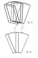
- FIGS. 2a and 2b are two ventilation installation elements 1, 1 'according to FIGS. 1 a and 1 b shown, which are joined together to form part of a ventilation according to the invention.
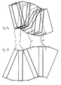
- FIGS. 3a and 3b are four ventilation installation elements 1, 1 ', 1 ", 1'" according to the FIGS. 1 a and 1 b shown, which are joined together to form part of a ventilation according to the invention. Since the two ventilation installation elements 1, 1 'redirect the air flow in one direction and the two other ventilation installation elements 1 ", 1"' redirect the air flow in the opposite direction, a lateral offset occurs without any change of direction due to the part of the ventilation shown.
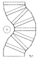
- FIG. 4 is another part of a ventilation according to the invention with eight ventilation installation elements (without reference numerals) according to FIGS. 1a and 1b illustrated, in which case the air flow around an obstacle 8, for example, an installation or electrical line, is guided around in a small footprint.
- an obstacle 8 for example, an installation or electrical line
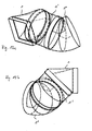
- FIGS. 5a and 5b a second embodiment of the ventilation installation element 1 according to the invention is shown.
- the longitudinal sides could also be bent around the deflection angle 3.
- the deflection takes place here in another spatial direction.
- FIGS. 5a and 5b are two ventilation installation elements 1, 1 'according to FIGS. 5a and 5b shown, which are joined together to form part of a ventilation according to the invention.
- FIGS. 7a and 7b are four ventilation installation elements 1, 1 ', 1 ", 1''' according to the FIGS. 5a and 5b shown, which are joined together to form part of a ventilation according to the invention. Since the two ventilation installation elements 1, 1 'redirect the air flow in one direction and the two other ventilation installation elements 1 ", 1''' redirect the air flow in the opposite direction, a height offset without change of direction takes place through the illustrated part of the ventilation.
- FIGS. 8a . 8b and 8c a third embodiment of a ventilation installation element according to the invention is shown in three views.
- the first connection opening 10 has a circular cross section, while the second connection opening 20 has a rectangular cross section, as in the ventilation installation elements shown above.
- the deflection angle 3 is also included here by the first plane 11 and the second plane 21.
- the deflection angle in this embodiment is about 45 °.
- the ventilation installation element according to this embodiment is applicable for the deflection of an air flow, as well as a transition piece between a rectangular tube and a round Pipe.
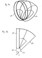
- FIGS. 9a and 9b a fourth embodiment of a ventilation installation element according to the invention is shown in two schematic views.
- the first connection opening 10 and the second connection opening 20 have a round cross-section.
- FIGS. 9a and 9b show a part of a ventilation according to the invention with two ventilation installation elements 1, 1 'according to FIGS. 9a and 9b in two schematic views.
- An advantage of the illustrated combination of two ventilation installation elements according to this embodiment is that by turning the ventilation installation elements 1, 1 'against each other, a deflection of the air flow in any spatial direction is possible, the maximum achievable angle corresponds to twice the deflection angle.
- FIGS. 1 a and 1b show a part of a ventilation according to the invention with a combination of the ventilation installation elements 1, 1 'according to FIGS. 1 a and 1b, and 5a and 5b.
- the deflection takes place after this combination, first in a first spatial direction and then in a second spatial direction, perpendicular to the first spatial direction.
- the ventilation installation elements according to the invention of all illustrated embodiments can advantageously be combined as desired.
- FIGS. 12a and 12b show a part of a ventilation according to the invention with a combination of the ventilation installation elements 1 according to FIGS. 8a and 8b with ventilation installation elements 1 'according to FIGS. 9a and 9b in two schematic views.
- the deflection after this combination can be done in any spatial direction.
- the ventilation installation element 1 represents a transition between an angular and a round tube cross-section.
- FIGS. 9a and 9b illustrated in two schematic views illustrating the possibility of any combination of the illustrated ventilation installation elements.
Landscapes
- Engineering & Computer Science (AREA)
- General Engineering & Computer Science (AREA)
- Mechanical Engineering (AREA)
- Chemical & Material Sciences (AREA)
- Combustion & Propulsion (AREA)
- Building Environments (AREA)
- Air-Flow Control Members (AREA)
Applications Claiming Priority (1)
| Application Number | Priority Date | Filing Date | Title |
|---|---|---|---|
| DE200710023004 DE102007023004A1 (de) | 2007-05-15 | 2007-05-15 | Lüftungsinstallationselement |
Publications (2)
| Publication Number | Publication Date |
|---|---|
| EP1992885A2 true EP1992885A2 (fr) | 2008-11-19 |
| EP1992885A3 EP1992885A3 (fr) | 2014-03-12 |
Family
ID=39629011
Family Applications (1)
| Application Number | Title | Priority Date | Filing Date |
|---|---|---|---|
| EP08008992.3A Withdrawn EP1992885A3 (fr) | 2007-05-15 | 2008-05-15 | Elément d'installation d'aération |
Country Status (2)
| Country | Link |
|---|---|
| EP (1) | EP1992885A3 (fr) |
| DE (1) | DE102007023004A1 (fr) |
Cited By (1)
| Publication number | Priority date | Publication date | Assignee | Title |
|---|---|---|---|---|
| CN111365543A (zh) * | 2020-03-26 | 2020-07-03 | 河北省安装工程有限公司 | 一种天圆地方管及其加工方法 |
Citations (1)
| Publication number | Priority date | Publication date | Assignee | Title |
|---|---|---|---|---|
| DE8700090U1 (de) | 1987-01-02 | 1987-02-19 | Bürcher, Friedrich, 8029 Sauerlach | Flachkanal-Lüftungsinstallationselemente |
Family Cites Families (9)
| Publication number | Priority date | Publication date | Assignee | Title |
|---|---|---|---|---|
| US193847A (en) * | 1877-08-07 | Improvement in stove-pipe elbows | ||
| US2904660A (en) * | 1957-03-15 | 1959-09-15 | Asea Ab | Air blast circuit breakers |
| GB1403744A (en) * | 1972-07-20 | 1975-08-28 | Piccoli D | Conduits joints comprising tubular elements of sheet metal |
| AT328807B (de) * | 1972-07-27 | 1976-04-12 | Osterreichische Symalen Ges M | Vorrichtung zur herstellung eines rohrkrummerelementes |
| FR2255538A1 (en) * | 1973-12-21 | 1975-07-18 | Martin Emile | Assembly of ventilation ducts for ship - has standard units cut to length and interlinked |
| US5957506A (en) * | 1998-02-27 | 1999-09-28 | M & M Manufacturing Co., Inc. | Sheet-metal insulated register box with adjustable elbow fitting |
| US7097804B2 (en) * | 2002-08-09 | 2006-08-29 | The Boeing Company | Thermoplastic laminate duct |
| ES2239525B1 (es) * | 2003-12-03 | 2006-10-16 | Carlos Alonso Gonzalez | Estructura perfeccionada modular y adaptable de conductos de aire para climatizacion y ventilacion. |
| DE202006006756U1 (de) * | 2006-04-26 | 2006-07-06 | Bürcher, Friedrich | Kanalelemente für einen Kanal zum Führen von Strömungsmedien, Kabeln u.dgl. |
-
2007
- 2007-05-15 DE DE200710023004 patent/DE102007023004A1/de not_active Withdrawn
-
2008
- 2008-05-15 EP EP08008992.3A patent/EP1992885A3/fr not_active Withdrawn
Patent Citations (1)
| Publication number | Priority date | Publication date | Assignee | Title |
|---|---|---|---|---|
| DE8700090U1 (de) | 1987-01-02 | 1987-02-19 | Bürcher, Friedrich, 8029 Sauerlach | Flachkanal-Lüftungsinstallationselemente |
Cited By (2)
| Publication number | Priority date | Publication date | Assignee | Title |
|---|---|---|---|---|
| CN111365543A (zh) * | 2020-03-26 | 2020-07-03 | 河北省安装工程有限公司 | 一种天圆地方管及其加工方法 |
| CN111365543B (zh) * | 2020-03-26 | 2021-06-25 | 河北省安装工程有限公司 | 一种天圆地方管及其加工方法 |
Also Published As
| Publication number | Publication date |
|---|---|
| DE102007023004A1 (de) | 2008-11-20 |
| EP1992885A3 (fr) | 2014-03-12 |
Similar Documents
| Publication | Publication Date | Title |
|---|---|---|
| DE69300051T2 (de) | Verbinder für geschweisste Gitter. | |
| DE102009021596B4 (de) | Teleskopierbares Rohrsystem für einen Staubsauger | |
| EP2930412B1 (fr) | Procédé de fabrication d'un connecteur à fiches et connecteur à fiches | |
| DE202010009598U1 (de) | Steckverbinder mit Außenleiterschirm | |
| EP3791454A1 (fr) | Traversée de paroi | |
| EP4067753B1 (fr) | Une hotte aspirante à circulation descendante avec agencement de conduit plat | |
| DE102016220527A1 (de) | Bogenelement für ein Lüftungssystem | |
| DE102007041663A1 (de) | Einrichtung zum Führen von Leitungen, Schläuchen oder dergleichen | |
| EP4092277B1 (fr) | Coude tubulaire pour un canal d'air d'évacuation d'une hotte aspirante | |
| EP1750339B1 (fr) | accessoire d'angle pour conduit électrique | |
| DE102007023004A1 (de) | Lüftungsinstallationselement | |
| EP2273638A2 (fr) | Pince pour canaux de câble destinée à masquer des bords de coupe | |
| EP3850254A1 (fr) | Traversée murale pour câbles | |
| EP3166808B1 (fr) | Mécanisme de commande électromécanique | |
| EP2971923A1 (fr) | Pièce de raccordement de tuyau | |
| EP3540883A1 (fr) | Manchon de guidage de câble et procédé de raccordement des éléments de guidage de câble | |
| EP3364119B1 (fr) | Élément de déviation | |
| DE202017104269U1 (de) | Dunstabzugssystem | |
| DE20105092U1 (de) | Anschlusseinrichtung für einen Heizkörper sowie Winkelstück hierfür | |
| EP3101318B1 (fr) | Module de vanne | |
| EP3896234A1 (fr) | Système de robinetterie | |
| DE102019106108A1 (de) | Einstellbar abgewinkelter Knickschutz für ein Kabel und Kabel mit diesem Knickschutz | |
| DE102013206873A1 (de) | Lüftungsdüse | |
| DE102007063641A1 (de) | Verbindungsanordnung für den Installationsbereich | |
| WO2016124621A1 (fr) | Dispositif de guidage d'énergie et système de traitement de pièces |
Legal Events
| Date | Code | Title | Description |
|---|---|---|---|
| PUAI | Public reference made under article 153(3) epc to a published international application that has entered the european phase |
Free format text: ORIGINAL CODE: 0009012 |
|
| AK | Designated contracting states |
Kind code of ref document: A2 Designated state(s): AT BE BG CH CY CZ DE DK EE ES FI FR GB GR HR HU IE IS IT LI LT LU LV MC MT NL NO PL PT RO SE SI SK TR |
|
| AX | Request for extension of the european patent |
Extension state: AL BA MK RS |
|
| 19U | Interruption of proceedings before grant |
Effective date: 20120401 |
|
| 19W | Proceedings resumed before grant after interruption of proceedings |
Effective date: 20130902 |
|
| RAP1 | Party data changed (applicant data changed or rights of an application transferred) |
Owner name: RUG SEMIN GMBH |
|
| PUAL | Search report despatched |
Free format text: ORIGINAL CODE: 0009013 |
|
| AK | Designated contracting states |
Kind code of ref document: A3 Designated state(s): AT BE BG CH CY CZ DE DK EE ES FI FR GB GR HR HU IE IS IT LI LT LU LV MC MT NL NO PL PT RO SE SI SK TR |
|
| AX | Request for extension of the european patent |
Extension state: AL BA MK RS |
|
| RIC1 | Information provided on ipc code assigned before grant |
Ipc: F16L 25/00 20060101ALI20140131BHEP Ipc: F16L 25/14 20060101ALI20140131BHEP Ipc: F24F 13/02 20060101AFI20140131BHEP Ipc: F16L 43/00 20060101ALI20140131BHEP Ipc: E04F 17/04 20060101ALI20140131BHEP |
|
| STAA | Information on the status of an ep patent application or granted ep patent |
Free format text: STATUS: THE APPLICATION IS DEEMED TO BE WITHDRAWN |
|
| 18D | Application deemed to be withdrawn |
Effective date: 20140304 |