EP1992914A2 - Dispositif de déplacement incrémentiel et procédé de détermination d'un déplacement d'un premier objet par rapport à un second objet - Google Patents
Dispositif de déplacement incrémentiel et procédé de détermination d'un déplacement d'un premier objet par rapport à un second objet Download PDFInfo
- Publication number
- EP1992914A2 EP1992914A2 EP08009021A EP08009021A EP1992914A2 EP 1992914 A2 EP1992914 A2 EP 1992914A2 EP 08009021 A EP08009021 A EP 08009021A EP 08009021 A EP08009021 A EP 08009021A EP 1992914 A2 EP1992914 A2 EP 1992914A2
- Authority
- EP
- European Patent Office
- Prior art keywords
- sensors
- sensor
- displacement
- value
- subgroup
- Prior art date
- Legal status (The legal status is an assumption and is not a legal conclusion. Google has not performed a legal analysis and makes no representation as to the accuracy of the status listed.)
- Granted
Links
Images

Classifications
-
- G—PHYSICS
- G01—MEASURING; TESTING
- G01D—MEASURING NOT SPECIALLY ADAPTED FOR A SPECIFIC VARIABLE; ARRANGEMENTS FOR MEASURING TWO OR MORE VARIABLES NOT COVERED IN A SINGLE OTHER SUBCLASS; TARIFF METERING APPARATUS; MEASURING OR TESTING NOT OTHERWISE PROVIDED FOR
- G01D5/00—Mechanical means for transferring the output of a sensing member; Means for converting the output of a sensing member to another variable where the form or nature of the sensing member does not constrain the means for converting; Transducers not specially adapted for a specific variable
- G01D5/12—Mechanical means for transferring the output of a sensing member; Means for converting the output of a sensing member to another variable where the form or nature of the sensing member does not constrain the means for converting; Transducers not specially adapted for a specific variable using electric or magnetic means
- G01D5/244—Mechanical means for transferring the output of a sensing member; Means for converting the output of a sensing member to another variable where the form or nature of the sensing member does not constrain the means for converting; Transducers not specially adapted for a specific variable using electric or magnetic means influencing characteristics of pulses or pulse trains; generating pulses or pulse trains
- G01D5/245—Mechanical means for transferring the output of a sensing member; Means for converting the output of a sensing member to another variable where the form or nature of the sensing member does not constrain the means for converting; Transducers not specially adapted for a specific variable using electric or magnetic means influencing characteristics of pulses or pulse trains; generating pulses or pulse trains using a variable number of pulses in a train
- G01D5/2451—Incremental encoders
-
- G—PHYSICS
- G01—MEASURING; TESTING
- G01D—MEASURING NOT SPECIALLY ADAPTED FOR A SPECIFIC VARIABLE; ARRANGEMENTS FOR MEASURING TWO OR MORE VARIABLES NOT COVERED IN A SINGLE OTHER SUBCLASS; TARIFF METERING APPARATUS; MEASURING OR TESTING NOT OTHERWISE PROVIDED FOR
- G01D5/00—Mechanical means for transferring the output of a sensing member; Means for converting the output of a sensing member to another variable where the form or nature of the sensing member does not constrain the means for converting; Transducers not specially adapted for a specific variable
- G01D5/12—Mechanical means for transferring the output of a sensing member; Means for converting the output of a sensing member to another variable where the form or nature of the sensing member does not constrain the means for converting; Transducers not specially adapted for a specific variable using electric or magnetic means
- G01D5/244—Mechanical means for transferring the output of a sensing member; Means for converting the output of a sensing member to another variable where the form or nature of the sensing member does not constrain the means for converting; Transducers not specially adapted for a specific variable using electric or magnetic means influencing characteristics of pulses or pulse trains; generating pulses or pulse trains
- G01D5/249—Mechanical means for transferring the output of a sensing member; Means for converting the output of a sensing member to another variable where the form or nature of the sensing member does not constrain the means for converting; Transducers not specially adapted for a specific variable using electric or magnetic means influencing characteristics of pulses or pulse trains; generating pulses or pulse trains using pulse code
- G01D5/2492—Pulse stream
Definitions
- the present invention relates, in a first aspect, to an incremental displacement sensor according to the term of claim 1.
- the invention relates to a method for determining a displacement of a first object relative to a second object.
- a generic incremental encoder is used to determine a displacement of a first object relative to a second object and is for example off DE 197 01 319 A1 known.
- Such an incremental waveguide has a scanning unit connected or to be connected to the first object for scanning a pitch track connected to or connected to the second object with first areas and second areas alternately arranged with a period length.
- the first regions have a first physical property and the second regions have a different second physical property.
- the scanning unit has a plurality of sensors for scanning the first areas and second areas based on the first and / or the second physical property.
- an evaluation unit connected to the scanning unit is provided for determining the displacement on the basis of measuring signals of the sensors.
- a division track associated with the first object is scanned with a plurality of sensors connected to the second object.
- the division track has first areas with a first physical property and second regions having a second physical property, which are arranged alternately with a period length, and from measurement signals of the sensors, which are obtained on the basis of the first and / or the second physical property, the displacement of the first object relative to the second object is determined.
- Inductive incremental displacement sensors are also available in DE 31 00 486 A1 .
- US 6,885,310 B2 and US 6,552,666 B1 disclose apparatuses and methods for detecting a phase difference for a position detector.
- EP 0 795 738 B1 and EP 0 446 969 B1 treat inductive linear position detection devices.
- EP 0 473 808 A1 has a measuring device for determining a path or a position to the object.
- Incremental encoders are used to measure changes in position.
- two mutually offset sensors each determine the position of a graduation track.
- the movement of the pitch track relative to the sensors can be determined. Since the signals generated by the two sensors have a phase offset of, for example 90 °, also a direction detection is possible.
- the desired 1: 1 pulse-pause ratio for the direction detection can only be achieved for a certain distance.
- the object of the invention is to provide an incremental displacement sensor and a method for determining the displacement of a first object relative to a second object, in which reliable measurement results are provided largely independently of the actual distance of the sensors used to a graduation track.
- the object is achieved by the method having the features of claim 10.
- the scanning unit has at least three sensors, in particular distributed along the pitch track, distributed over at least one period length spaced from each other, that in the evaluation unit for determining the shift, a first switching signal and a second switching signal is generated from the measurement signals of the sensors, that the first switching signal assumes a first value, in particular HIGH, if the sensor which outputs a maximum measuring signal belongs to a first subgroup of sensors, and otherwise assumes a second value, in particular LOW, in that the second switching signal assumes a first value, in particular HIGH, if the sensor which outputs a maximum measuring signal belongs to a second subgroup of sensors and otherwise assumes a second value, in particular LOW, and wherein at least one sensor is assigned both to the first subgroup e as well as the second subgroup.
- the method of the abovementioned type is developed according to the invention in that at least three sensors are arranged distributed along the pitch track distributed over at least one period length, that the shift is determined based on a first switching signal and a second switching signal that the first switching signal has a first value , in particular HIGH, assumes that the sensor which outputs a maximum measuring signal to a first subgroup heard from sensors, and otherwise a second value, in particular LOW, assumes that the second switching signal assumes a first value, in particular HIGH, if the sensor which outputs a maximum measurement signal belongs to a second subset of sensors, and otherwise a second value , in particular LOW, and wherein at least one sensor belongs to both the first subgroup and the second subgroup.
- the invention contiguous with it, involves arranging at least three sensors over a period of the graduation track and subdividing these sensors into subgroups, wherein at least one sensor is part of both subgroups.
- a first significant advantage of the solution according to the invention consists in the distance independence of the evaluation. This allows a particularly wide range of applications in the industrial sector, since a precise device of the measuring device with respect to the graduation track is not required.
- a second significant advantage can be seen in the fact that the division track, in fundamental difference to known solutions, does not have to have a 1: 1 division.
- any periodic structure can be used to generate the incremental signal.
- the maximum measurement signal is to be understood here as the measurement signal which is supplied to the sensor in question at the maximum approximation of the corresponding first or second range from this same sensor.
- this may possibly also be a minimum value.
- the latter is the case, for example, when the movement of a metal sheet is determined with an inductive sensor, in which holes are located at periodic but comparatively large distances. If a sensor is positioned directly in front of the hole, the damping drops down to a minimum value which, however, based on the full attenuation, is a maximum value, namely a value of maximum deviation.
- the signals from two adjacent sensors overlap within the desired detection range of the rail. This means that the lateral distance of two adjacent sensors in relation to the lateral extent of the smaller of the two regions of the graduation track is selected such that, in any case, temporarily both sensors supply a detection signal based on this region.
- the web width of a flag of a division track must have a certain minimum width, so that at least temporarily two adjacent sensors provide a signal due to this flag.
- the said condition can therefore be met on the one hand by a certain minimum width of the first and / or the second region and on the other hand by a certain lateral maximum distance of the sensors.
- the sensors can basically be arranged arbitrarily distributed over a period of the graduation track or over several periods.
- variable distances of the sensors from each other are also possible, but in preferred embodiments, the sensors are arranged evenly spaced from one another, since in this case the evaluation is simpler.
- the target width that is, for example, the width or lateral extent of the first area
- a gap width that is, a lateral extent of the second area.
- the switching signals can also be output inverted, that is, the value LOW is output instead of the value HIGH and vice versa.
- any physical property that can be determined with sensors can be used to form the graduation track.
- the first and the second regions may have different magnetic, optical or also mechanical properties.
- first regions are electrically conductive and the second regions are electrically insulating and the sensors are inductive sensors.
- Two phase-offset distance-independent signals can be generated when the scanning unit has three sensors, wherein the first subgroup is formed by the first and the second sensor and the second subgroup by the second and the third sensor. On the sensor side, this requires a minimum of components.
- the scanning unit has four sensors and the first subgroup is formed by the first and the second sensor and the second subgroup by the second and the third sensor.
- the first subgroup is formed by the first and the second sensor and the second subgroup by the second and the third sensor.
- two 90 ° out of phase switching signals can be obtained, and in addition, if the division track has a 1: 1 division ratio, known evaluation algorithms can be used.
- the sensors are arranged at a distance of 1/4 of the pitch period.
- the scanning unit may comprise eight sensors and the first subgroup may be formed by the first, the second and the fifth and the sixth sensor and the second subgroup may be formed by the second, the third and the sixth and the seventh sensor.
- the numerical designation of the sensors should be understood here so that, for example, arranged in a row sensors, the sensor on the left as the first then the right subsequent as the second and for example the right outside sensor is referred to as the eighth sensor.
- the division track can basically consist of any periodic structure which has suitable physical properties with regard to the scanning.
- an already existing perforated grid can serve as a graduation track on a moving or monitored device.
- the selection of the sensors for the first and the second subgroup, for the formation of the first and second switching signal can, as long as the condition that the subgroups in each case contain at least one common sensor, in principle be arbitrary.
- the evaluation is easier if the first subgroup and the second subset contain the same number of sensors.
- the first and the second subgroup each contain half of all sensors. This also means that the number of sensors is even.
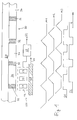
- the incremental wave transmitter 100 has as essential components a scanning unit 22 arranged on a first object 10 with a plurality of sensors C1, C2, C3, which is connected to an evaluation unit 60.
- the sensors C1, C2, C3 of the scanning unit 22 are used for scanning a graduation track 30, which is arranged on a second object 20.
- the graduation track 30 consists essentially of periodically alternately arranged first regions 32 and second regions 34. These each have different physical properties, whereby the scanning of the sensors C1, C2, C3 is possible.
- the first regions 32 may be electrically conductive metallic tabs and, accordingly, the second regions 34 may be holes or recesses in a sheet.
- the sensors C1, C2, C3 are then expedient inductive sensors, such as inductive proximity switches.
- Fig. 1 In the case of lateral relative movement of the first object 10 with respect to the second object 20 in the direction arranged by an arrow 24, the time profiles of the measurement signals M1, M2, M3 and the switching signals S1, S2 derived therefrom in the evaluation unit 60 are obtained Fig. 1 are shown schematically.
- the signal M1 belongs to the sensor C1, the signal M2 to the sensor C2 and the signal M3 to the sensor C3.
- the measurement signal is maximum, if the corresponding sensor, immediately before a conductive first region 32, the damping of the proximity switch, that is maximum.
- the measurement signals M1, M2, M3 have a phase offset of 120 ° over the period of the graduation track 30 due to the arrangement of the sensors C1, C2, C3.
- switching signals S1 and S2 are obtained in the evaluation unit 60 by a logical evaluation, which switches the signal S1 to HIGH, when the maximum measurement signal is supplied either from the sensor C1 or C2 and is otherwise switched to LOW. Furthermore, the signal S2 is switched to HIGH when the maximum signal is supplied from one of the sensors C2 or C3, but otherwise switched to LOW. Accordingly, in this embodiment, the sensor C2 is part of both the first and second subset of sensors.
- the relative velocity in one direction can be used to determine the speed of this displacement and, if a suitable start signal is present, also the absolute value of the displacement.
- information about the direction can be seen from the relative phase angle of the signals S1 and S2, can be obtained from the chronological sequence of these switching signals.
- the evaluation unit 60 delivers a displacement signal x (t) for further use, for example in a process control.
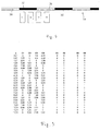
- FIG Fig. 2 A second exemplary embodiment of an incremental displacement sensor according to the invention is shown in FIG Fig. 2 shown.
- Equivalent components in all figures are given the same reference numerals as in FIG Fig. 1 Mistake.
- Fig. Are in the variant in Fig. 2 a total of four sensors C1, C2, C3 and C4 arranged along an extension direction 36 of the division track 30 over a period.
- the lateral extent, that is to say the extent in the extension direction 36, of the first regions 32 is here 1/4 of the period length p.
- the lateral extent of the second regions 34 is 3/4 of the period length p.
- the sensors C1, C2, C3 and C4 are as out Fig. 2 immediately apparent, arranged at a distance of 1/4 of the period length.
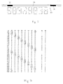
- the courses of the measuring signals of the sensors C1, C2, C3 and C4 and the switching signals S1 and S2 derived therefrom are tabulated in FIG Fig. 3 against a displacement x of the first object 10 relative to the second object 20. These courses correspond to those in Fig. 1 graphically represented signal curves.
- the logical switching condition here is that the switching signal S1 is switched to 1, if either the first sensor C1 or the second sensor C2 provides the maximum signal, but is otherwise set to 0.
- the switching signal S2 is set to 1 when the maximum signal is supplied from one of the sensors C2 or C3 and is otherwise 0.
- the values for the displacement x are in the table in FIG Fig. 3 just chosen so that the switching points are clarified.
- the switching conditions mentioned provide two switching signals S1 and S2 with a phase offset of 90 °.
- the further evaluation with regard to the location signal x (t) is then simple and it is possible to resort to known evaluation algorithms.
- FIGS. 4 and 5 A third embodiment of the incremental Weggebers invention is in connection with the FIGS. 4 and 5 described.
- Fig. 4 schematically shows the arrangement of a total of four sensors C1, C2, C3 and C4 along a division track 30.
- This embodiment corresponds essentially to the variant Fig. 3 , The only difference is that the lateral extent of the first regions 32 and the lateral extent of the second regions 34 of the graduation track 30 are each half of the period length p of the graduation track.
- This embodiment of the graduation track 30 makes it possible, in comparison to the evaluation according to the invention, to produce an alternative method of generating the switching signals necessary for position determination.
- the switching signals S3 and S4 are obtained by an alternative method, for which the sensors C1 and C3 are combined to a first sensor unit and the sensors C2 and C4 to a second sensor unit.
- the switching signal S3 is set to 1, when the sensor C1 compared to the sensor C3 delivers the larger measurement signal.
- FIGS. 6 and 7 A fourth exemplary embodiment of an incremental displacement sensor according to the invention is described in connection with FIGS FIGS. 6 and 7 explained.
- a total of eight sensors C1,..., C8 are arranged at intervals of 1/8 of the period length p over a period p of a graduation track.
- the division track is, as in the preceding examples, arranged on a second object, which is not shown separately here for reasons of clarity.
- the sensors are also, as in the preceding embodiments, part of a scanning unit which is arranged on a first object, which is likewise not shown here.
- the switching signal S2 is switched to 1 when the maximum measuring signal is supplied from one of the sensors C2, C3, C6 or C7. Accordingly, S2 is otherwise 0.
- the graduation track 30 can basically have any desired division ratio and that, independently of this, switching signals with a phase offset of 90 ° and in each case a duty ratio of 1: 1 are generated can be. This enables particularly diverse applications in the industrial sector.
- the present invention provides a novel incremental path sensor in which signal formation takes place by comparing sensor values, for example four individual sensors, which are arranged at a spacing of 1/4 of the period of a code rail or graduation track.
- the web-hole grid of the code rail need not be arranged in a 1: 1 ratio, but may also have other values, in particular 1: 4 or 1: 8. Evaluated in the invention described here, which sensors provide the maximum signal.
- the evaluation described here is as far as possible independent of distance, since it does not depend on the absolute measured values of the individual sensors.
- this method can be applied to any number of sensors per period.
- the accuracy of the displacement determination can be increased. For example, with eight sensors, as in the example of the FIGS. 6 and 7 represented, two pulses per period of the division track 30 are generated.
Landscapes
- Physics & Mathematics (AREA)
- General Physics & Mathematics (AREA)
- Transmission And Conversion Of Sensor Element Output (AREA)
- Length Measuring Devices By Optical Means (AREA)
Applications Claiming Priority (1)
| Application Number | Priority Date | Filing Date | Title |
|---|---|---|---|
| DE102007022942A DE102007022942A1 (de) | 2007-05-16 | 2007-05-16 | Inkrementalweggeber und Verfahren zum Bestimmen einer Verschiebung eines ersten Objekts relativ zu einem zweiten Objekt |
Publications (3)
| Publication Number | Publication Date |
|---|---|
| EP1992914A2 true EP1992914A2 (fr) | 2008-11-19 |
| EP1992914A3 EP1992914A3 (fr) | 2011-06-29 |
| EP1992914B1 EP1992914B1 (fr) | 2012-05-09 |
Family
ID=39666182
Family Applications (1)
| Application Number | Title | Priority Date | Filing Date |
|---|---|---|---|
| EP08009021A Active EP1992914B1 (fr) | 2007-05-16 | 2008-05-15 | Dispositif de déplacement incrémentiel et procédé de détermination d'un déplacement d'un premier objet par rapport à un second objet |
Country Status (3)
| Country | Link |
|---|---|
| US (1) | US7535216B2 (fr) |
| EP (1) | EP1992914B1 (fr) |
| DE (1) | DE102007022942A1 (fr) |
Cited By (1)
| Publication number | Priority date | Publication date | Assignee | Title |
|---|---|---|---|---|
| EP2072960A3 (fr) * | 2007-12-21 | 2012-05-02 | Pepperl + Fuchs GmbH | Dispositif de mesure incrémental de déplacement et procédé de détermination d'un déplacement d'un premier objet par rapport à un second objet |
Families Citing this family (3)
| Publication number | Priority date | Publication date | Assignee | Title |
|---|---|---|---|---|
| DE102016002487B3 (de) * | 2016-03-03 | 2017-08-03 | Tdk-Micronas Gmbh | Positionsbestimmungssensoreinheit |
| DE102016005826B4 (de) | 2016-05-17 | 2020-07-16 | Pepperl+Fuchs Ag | Positionsmesseinheit und Positionsmessverfahren |
| DE102022117186A1 (de) * | 2022-07-11 | 2024-01-11 | Ewellix AB | Positionsgeber, Linearaktuator und Verfahren zur Positionsbestimmung |
Citations (9)
| Publication number | Priority date | Publication date | Assignee | Title |
|---|---|---|---|---|
| DE3100486A1 (de) | 1980-01-10 | 1982-02-18 | Centro Ricerche Fiat S.p.A., 10043 Orbassano, Torino | Vorrichtung zur bestimmung der position eines schweissgeraetes zum selbsttaetigen lichtbogenschweissen |
| US4893078A (en) | 1987-05-28 | 1990-01-09 | Auchterlonie Richard C | Absolute position sensing using sets of windings of different pitches providing respective indications of phase proportional to displacement |
| US5003260A (en) | 1987-05-28 | 1991-03-26 | Auchterlonie Richard C | Inductive position sensor having plural phase windings on a support and a displaceable phase sensing element returning a phase indicating signal by electromagnetic induction to eliminate wire connections |
| EP0473808A1 (fr) | 1990-09-03 | 1992-03-11 | Hottinger Baldwin Messtechnik Gmbh | Dispositif de mesure pour la détermination d'un trajet ou d'une position |
| EP0446969B1 (fr) | 1984-02-10 | 1996-12-11 | Kabushiki Kaisha Sg | Dispositif de détection de la position linéaire |
| DE19701319A1 (de) | 1997-01-16 | 1998-07-23 | Heidenhain Gmbh Dr Johannes | Positionsmeßeinrichtung |
| EP0795738B1 (fr) | 1996-03-16 | 2001-10-24 | Atsutoshi Goto | Dispositif de détection de la position linéaire du type à induction |
| US6552666B1 (en) | 1996-03-16 | 2003-04-22 | Atsutoshi Goto | Phase difference detection device and method for a position detector |
| EP1071927B1 (fr) | 1998-04-16 | 2003-09-24 | Jean-Pierre Bazenet | Dispositif de mesure incrementale de position |
Family Cites Families (4)
| Publication number | Priority date | Publication date | Assignee | Title |
|---|---|---|---|---|
| DE4318386C2 (de) * | 1993-06-01 | 2002-09-19 | Rohm Co Ltd | Optische Encodervorrichtung zum Erfassen der Bewegung eines beweglichen Elements |
| DE19637855A1 (de) * | 1996-09-17 | 1998-03-19 | Teves Gmbh Alfred | Anordnung zur Erkennung einer Bewegungsrichtung, insbesondere einer Drehrichtung |
| DE19717364C1 (de) * | 1997-04-24 | 1998-08-27 | Siemens Ag | Verfahren zur Erkennung der Drehrichtung eines Rades mittels Hall-Sonden |
| DE19963809C2 (de) * | 1999-12-30 | 2002-01-17 | Osram Opto Semiconductors Gmbh | Optischer Encoder mit dreifacher Photodiode |
-
2007
- 2007-05-16 DE DE102007022942A patent/DE102007022942A1/de not_active Ceased
-
2008
- 2008-05-15 EP EP08009021A patent/EP1992914B1/fr active Active
- 2008-05-15 US US12/120,772 patent/US7535216B2/en active Active
Patent Citations (10)
| Publication number | Priority date | Publication date | Assignee | Title |
|---|---|---|---|---|
| DE3100486A1 (de) | 1980-01-10 | 1982-02-18 | Centro Ricerche Fiat S.p.A., 10043 Orbassano, Torino | Vorrichtung zur bestimmung der position eines schweissgeraetes zum selbsttaetigen lichtbogenschweissen |
| EP0446969B1 (fr) | 1984-02-10 | 1996-12-11 | Kabushiki Kaisha Sg | Dispositif de détection de la position linéaire |
| US4893078A (en) | 1987-05-28 | 1990-01-09 | Auchterlonie Richard C | Absolute position sensing using sets of windings of different pitches providing respective indications of phase proportional to displacement |
| US5003260A (en) | 1987-05-28 | 1991-03-26 | Auchterlonie Richard C | Inductive position sensor having plural phase windings on a support and a displaceable phase sensing element returning a phase indicating signal by electromagnetic induction to eliminate wire connections |
| EP0473808A1 (fr) | 1990-09-03 | 1992-03-11 | Hottinger Baldwin Messtechnik Gmbh | Dispositif de mesure pour la détermination d'un trajet ou d'une position |
| EP0795738B1 (fr) | 1996-03-16 | 2001-10-24 | Atsutoshi Goto | Dispositif de détection de la position linéaire du type à induction |
| US6552666B1 (en) | 1996-03-16 | 2003-04-22 | Atsutoshi Goto | Phase difference detection device and method for a position detector |
| US6885310B2 (en) | 1996-03-16 | 2005-04-26 | Atsutoshi Goto | Phase difference detection device and method for a position detector |
| DE19701319A1 (de) | 1997-01-16 | 1998-07-23 | Heidenhain Gmbh Dr Johannes | Positionsmeßeinrichtung |
| EP1071927B1 (fr) | 1998-04-16 | 2003-09-24 | Jean-Pierre Bazenet | Dispositif de mesure incrementale de position |
Cited By (1)
| Publication number | Priority date | Publication date | Assignee | Title |
|---|---|---|---|---|
| EP2072960A3 (fr) * | 2007-12-21 | 2012-05-02 | Pepperl + Fuchs GmbH | Dispositif de mesure incrémental de déplacement et procédé de détermination d'un déplacement d'un premier objet par rapport à un second objet |
Also Published As
| Publication number | Publication date |
|---|---|
| EP1992914A3 (fr) | 2011-06-29 |
| US7535216B2 (en) | 2009-05-19 |
| DE102007022942A1 (de) | 2008-11-20 |
| EP1992914B1 (fr) | 2012-05-09 |
| US20080284417A1 (en) | 2008-11-20 |
Similar Documents
| Publication | Publication Date | Title |
|---|---|---|
| EP2502030B1 (fr) | Dispositif de mesure inductif pour l'acquisition de longueur et d'angle | |
| EP2183550B2 (fr) | Capteur de parcours inductif, dispositif de codage, et procédé de détermination d'une position d'un premier objet par rapport à un second objet | |
| EP1649250B2 (fr) | Dispositif et procede pour mesurer la trajectoire d'un objet cible | |
| EP3040688B1 (fr) | Encodeur linéaire capacitif | |
| EP2126517B1 (fr) | Capteur de déplacement incrémentiel inductif et procédé de détermination du décalage d'un premier objet par rapport à un deuxième objet | |
| EP0461300B1 (fr) | Méthode pour mesurer une longueur et pied à coulisse électronique | |
| EP1992914B1 (fr) | Dispositif de déplacement incrémentiel et procédé de détermination d'un déplacement d'un premier objet par rapport à un second objet | |
| EP1995566A2 (fr) | Echelle pour un dispositif de mesure de position et dispositif de mesure de position | |
| DE112010003273T5 (de) | Eine Vorrichtung und ein Verfahren für kapazitive lineare Verlagerungsmessung | |
| EP2869031B1 (fr) | Dispositif de mesure de position | |
| DE10162849B4 (de) | Längenmesssystem, bei dem ein Massstab relativ zur Position von beabstandeten Längensensoren bewegt wird | |
| EP1770373A1 (fr) | Dispositif de mesure de la position absolue | |
| EP2072960B1 (fr) | Dispositif de mesure incrémental de déplacement et procédé de détermination d'un déplacement d'un premier objet par rapport à un second objet | |
| EP4279874B1 (fr) | Dispositif inductif de mesure de position | |
| EP2116814A1 (fr) | Dispositif de mesure destiné à la détermination d'une position et/ou d'une vitesse | |
| DE10124761A1 (de) | Verfahren zur kontaktlosen, linearen Positionsmessung | |
| DE10158942B4 (de) | Vorrichtung und Verfahren zur Detektion der Position eines Messobjekts | |
| DE102013226200A1 (de) | Absolute Positionsmessvorrichtung | |
| DE102011008880A1 (de) | Anordnung und Verfahren zur Erfassung von Absolutpositionen eines Messkopfs mit einer Reihe magnetischer Sensoren | |
| DE102023209159A1 (de) | Induktives positionsbestimmungssystem mit variierender spulengeometrie und entsprechendes verfahren zur positionsbestimmung | |
| CH710404A1 (de) | Magnetisches Drehwinkel- oder Wegmesssystem mit Referenzimpuls. | |
| EP1783462A1 (fr) | Dispositif de mesure d'angle |
Legal Events
| Date | Code | Title | Description |
|---|---|---|---|
| PUAI | Public reference made under article 153(3) epc to a published international application that has entered the european phase |
Free format text: ORIGINAL CODE: 0009012 |
|
| AK | Designated contracting states |
Kind code of ref document: A2 Designated state(s): AT BE BG CH CY CZ DE DK EE ES FI FR GB GR HR HU IE IS IT LI LT LU LV MC MT NL NO PL PT RO SE SI SK TR |
|
| AX | Request for extension of the european patent |
Extension state: AL BA MK RS |
|
| PUAL | Search report despatched |
Free format text: ORIGINAL CODE: 0009013 |
|
| AK | Designated contracting states |
Kind code of ref document: A3 Designated state(s): AT BE BG CH CY CZ DE DK EE ES FI FR GB GR HR HU IE IS IT LI LT LU LV MC MT NL NO PL PT RO SE SI SK TR |
|
| AX | Request for extension of the european patent |
Extension state: AL BA MK RS |
|
| 17P | Request for examination filed |
Effective date: 20110629 |
|
| GRAP | Despatch of communication of intention to grant a patent |
Free format text: ORIGINAL CODE: EPIDOSNIGR1 |
|
| RAP1 | Party data changed (applicant data changed or rights of an application transferred) |
Owner name: PEPPERL + FUCHS GMBH |
|
| AKX | Designation fees paid |
Designated state(s): CH DE FR GB LI |
|
| GRAS | Grant fee paid |
Free format text: ORIGINAL CODE: EPIDOSNIGR3 |
|
| GRAA | (expected) grant |
Free format text: ORIGINAL CODE: 0009210 |
|
| AK | Designated contracting states |
Kind code of ref document: B1 Designated state(s): CH DE FR GB LI |
|
| REG | Reference to a national code |
Ref country code: GB Ref legal event code: FG4D Free format text: NOT ENGLISH |
|
| REG | Reference to a national code |
Ref country code: CH Ref legal event code: NV Representative=s name: BOGENSBERGER PATENT- & MARKENBUERO DR. BURKHARD BO Ref country code: CH Ref legal event code: EP |
|
| REG | Reference to a national code |
Ref country code: DE Ref legal event code: R096 Ref document number: 502008007162 Country of ref document: DE Effective date: 20120705 |
|
| PLBE | No opposition filed within time limit |
Free format text: ORIGINAL CODE: 0009261 |
|
| STAA | Information on the status of an ep patent application or granted ep patent |
Free format text: STATUS: NO OPPOSITION FILED WITHIN TIME LIMIT |
|
| 26N | No opposition filed |
Effective date: 20130212 |
|
| REG | Reference to a national code |
Ref country code: CH Ref legal event code: PCAR Free format text: NEW ADDRESS: FALLSGASSE 7, 9492 ESCHEN (LI) |
|
| REG | Reference to a national code |
Ref country code: DE Ref legal event code: R097 Ref document number: 502008007162 Country of ref document: DE Effective date: 20130212 |
|
| REG | Reference to a national code |
Ref country code: FR Ref legal event code: PLFP Year of fee payment: 9 |
|
| PGFP | Annual fee paid to national office [announced via postgrant information from national office to epo] |
Ref country code: GB Payment date: 20160407 Year of fee payment: 9 |
|
| REG | Reference to a national code |
Ref country code: FR Ref legal event code: PLFP Year of fee payment: 10 |
|
| GBPC | Gb: european patent ceased through non-payment of renewal fee |
Effective date: 20170515 |
|
| PG25 | Lapsed in a contracting state [announced via postgrant information from national office to epo] |
Ref country code: GB Free format text: LAPSE BECAUSE OF NON-PAYMENT OF DUE FEES Effective date: 20170515 |
|
| REG | Reference to a national code |
Ref country code: FR Ref legal event code: PLFP Year of fee payment: 11 |
|
| REG | Reference to a national code |
Ref country code: DE Ref legal event code: R082 Ref document number: 502008007162 Country of ref document: DE Representative=s name: SCHIFFER, AXEL, DIPL.-PHYS.UNIV. DR.RER.NAT., DE |
|
| PGFP | Annual fee paid to national office [announced via postgrant information from national office to epo] |
Ref country code: CH Payment date: 20180523 Year of fee payment: 11 |
|
| PGFP | Annual fee paid to national office [announced via postgrant information from national office to epo] |
Ref country code: FR Payment date: 20180522 Year of fee payment: 11 |
|
| REG | Reference to a national code |
Ref country code: CH Ref legal event code: PL |
|
| PG25 | Lapsed in a contracting state [announced via postgrant information from national office to epo] |
Ref country code: CH Free format text: LAPSE BECAUSE OF NON-PAYMENT OF DUE FEES Effective date: 20190531 Ref country code: LI Free format text: LAPSE BECAUSE OF NON-PAYMENT OF DUE FEES Effective date: 20190531 |
|
| PG25 | Lapsed in a contracting state [announced via postgrant information from national office to epo] |
Ref country code: FR Free format text: LAPSE BECAUSE OF NON-PAYMENT OF DUE FEES Effective date: 20190531 |
|
| PGFP | Annual fee paid to national office [announced via postgrant information from national office to epo] |
Ref country code: DE Payment date: 20250519 Year of fee payment: 18 |