EP1992923B1 - Système indicateur de niveau de radar avec contrôle de puissance de transmission adaptatif - Google Patents
Système indicateur de niveau de radar avec contrôle de puissance de transmission adaptatif Download PDFInfo
- Publication number
- EP1992923B1 EP1992923B1 EP20080156278 EP08156278A EP1992923B1 EP 1992923 B1 EP1992923 B1 EP 1992923B1 EP 20080156278 EP20080156278 EP 20080156278 EP 08156278 A EP08156278 A EP 08156278A EP 1992923 B1 EP1992923 B1 EP 1992923B1
- Authority
- EP
- European Patent Office
- Prior art keywords
- electromagnetic signals
- power level
- gauge system
- transmitted
- level gauge
- Prior art date
- Legal status (The legal status is an assumption and is not a legal conclusion. Google has not performed a legal analysis and makes no representation as to the accuracy of the status listed.)
- Not-in-force
Links
- 230000005540 biological transmission Effects 0.000 title claims description 19
- 230000003044 adaptive effect Effects 0.000 title 1
- 238000012545 processing Methods 0.000 claims description 8
- 238000000034 method Methods 0.000 claims description 7
- 230000002123 temporal effect Effects 0.000 claims description 4
- 230000007613 environmental effect Effects 0.000 claims description 3
- 238000002156 mixing Methods 0.000 claims description 2
- 238000005259 measurement Methods 0.000 description 15
- 230000033228 biological regulation Effects 0.000 description 9
- 238000009434 installation Methods 0.000 description 3
- 230000003466 anti-cipated effect Effects 0.000 description 2
- 239000003990 capacitor Substances 0.000 description 2
- 238000010586 diagram Methods 0.000 description 2
- 230000000694 effects Effects 0.000 description 2
- 238000013507 mapping Methods 0.000 description 2
- 230000001902 propagating effect Effects 0.000 description 2
- 230000003321 amplification Effects 0.000 description 1
- 230000002238 attenuated effect Effects 0.000 description 1
- 238000004891 communication Methods 0.000 description 1
- 230000001276 controlling effect Effects 0.000 description 1
- 230000002349 favourable effect Effects 0.000 description 1
- 230000005669 field effect Effects 0.000 description 1
- 238000001914 filtration Methods 0.000 description 1
- 238000012544 monitoring process Methods 0.000 description 1
- 238000003199 nucleic acid amplification method Methods 0.000 description 1
- 230000000644 propagated effect Effects 0.000 description 1
- 230000001105 regulatory effect Effects 0.000 description 1
- 230000006641 stabilisation Effects 0.000 description 1
- 238000011105 stabilization Methods 0.000 description 1
Images


Classifications
-
- G—PHYSICS
- G01—MEASURING; TESTING
- G01F—MEASURING VOLUME, VOLUME FLOW, MASS FLOW OR LIQUID LEVEL; METERING BY VOLUME
- G01F23/00—Indicating or measuring liquid level or level of fluent solid material, e.g. indicating in terms of volume or indicating by means of an alarm
- G01F23/22—Indicating or measuring liquid level or level of fluent solid material, e.g. indicating in terms of volume or indicating by means of an alarm by measuring physical variables, other than linear dimensions, pressure or weight, dependent on the level to be measured, e.g. by difference of heat transfer of steam or water
- G01F23/28—Indicating or measuring liquid level or level of fluent solid material, e.g. indicating in terms of volume or indicating by means of an alarm by measuring physical variables, other than linear dimensions, pressure or weight, dependent on the level to be measured, e.g. by difference of heat transfer of steam or water by measuring the variations of parameters of electromagnetic or acoustic waves applied directly to the liquid or fluent solid material
- G01F23/284—Electromagnetic waves
Definitions
- the present invention relates to a radar level gauge system, for determining a filling level of a product.
- Radar level gauge systems are today in use in a variety of fields of application for accurate level determination, as well as for determination of other product parameters, such as temperature, flow etc.
- electromagnetic signals are transmitted and propagated, usually by means of an antenna, towards a surface of the product, where signals are reflected.
- the reflected signals are received by the radar level gauge system, and the distance between a reference position and the surface of the product is determined by comparing the transmitted signals with the reflected signals. Based on this distance, the filling level can be determined.
- a radar level gauge system Especially in open or semi-open applications, such as open tanks, floating-roof tanks, reservoirs, or even rivers or lakes, the operation of a radar level gauge system is typically subject to government regulations in respect of such parameters as the frequency and power of the transmitted signals.
- the transmission power should be limited to a certain level.
- the average emitted power, over time or for a given number of sources of emission may be limited to a certain level.
- a higher peak power may be permitted so long as the spatial and/or temporal average is below the stipulated value.
- the quality-of-measurement such as the accuracy with respect to distance, of the radar level gauge system should not be sacrificed to obtain this transmission power level.
- Conventional radar level gauge systems are generally not well adapted to fulfilling transmission power related regulations while at the same time achieving a high quality-of-measurement level.
- US20070101810 discloses a pulsed radar level gauge, comprising means for varying the output power of the transmitter during transmission of a pulse train, in order to adjust an amplitude of an analogue reflection signal to match the dynamics of the A/D converter of the radar level gauge.
- a general object of the present invention is to provide an improved radar level gauge system, and in particular a radar level gauge system capable of combining a sufficiently low transmission power to comply with various regulations with a high quality-of-measurement, including measurement accuracy.
- the propagation device should, in the context of the present application, be understood a device capable of propagating electromagnetic signals.
- the propagation device may be an antenna, such as a horn antenna, a rod antenna, a patch antenna, an array antenna etc.
- the antenna is often referred to as mode converter or mode generator.
- the tank may be any container or vessel capable of containing a product, and may be metallic, or partly or completely non-metallic, open, semi-open, or closed.
- the transmitter branch and the receiver branch may be physically separated, or may coincide.
- the transmitter and receiver branches may, for example, be implemented utilizing a so-called "leaky mixer".
- the present invention is based upon the realization that the fulfillment of various regulations in respect of power transmitted by a radar level gauge system can be achieved, while maintaining a high quality-of-measurement, by distributing the transmitted power, in time and/or between individual radar level gauge systems comprised in an installation including a plurality of radar level gauge systems, which may, for example, be arranged to determine the filling level in different tanks, in such a way that the transmitted power "budget" is used where it is most useful. Furthermore, the present inventor has realized that such a distribution of power combined with a high quality-of-measurement is enabled by determining the relevant received power level received by the radar level gauge system, and then adjusting the transmitted power level such that the received power level does not exceed a level at which a sufficiently high quality measurement can be performed.
- the total power transmitted by the above-mentioned multi-radar level gauge system installation can be channeled from, for example, radar level gauge systems that have very favorable measurement conditions to radar level gauge systems that need to transmit more power to produce a high quality measurement.
- the transmitted power level of a single radar level gauge system may vary over time depending on measurement conditions etc, so that the temporal average power transmitted by that particular radar level gauge system is kept below a certain, regulated value.
- a further effect achieved through the present invention is that the power consumption of the radar level gauge system can be minimized, given a certain desired quality-of-measurement.
- a radar level gauge system will typically, in addition to the electromagnetic signals reflected at the surface to be gauged, receive signals that have been reflected at various other locations, for example by fixed structures in the tank or other environment.
- the power sensing circuitry comprised in the radar level gauge system according to the present invention may therefore advantageously be configured to discriminate the reflected electromagnetic signals originating from reflection at the surface of the product to be gauged. In this way, the transmission power level can be adjusted based on the correct reflected signals.
- the power level adjusting circuitry comprised in the radar level gauge system according to the present invention may comprise controllable amplifier circuitry and/or controllable attenuator circuitry provided on the transmitter branch of the transceiver.
- controllable amplifier and/or attenuator circuitry includes various types of commercially available amplifiers and attenuators, as well as custom made amplifier/attenuator circuitry such as can be realized using one or several suitable transistors and passive components.
- the circuitry may advantageously be designed in such a way that the equivalent waveguide length thereof is substantially independent of the environmental conditions, such as temperature, and/or operating point, in respect of amplification and/or attenuation setting, of the power adjusting circuitry.
- the power level adjusting circuitry may advantageously be designed in such a way that an equivalent length of a transmission path of the electromagnetic signals therethrough is considerably shorter than the wavelength of the electromagnetic signals, such as shorter than half the wavelength of the electromagnetic signals. Consequently, the extension of the power level adjusting circuitry can be permitted to be larger for a larger wavelength of the electromagnetic signals.
- This minimum physical extension can, for example, be realized by not implementing various stub lines etc that are typically used for microwave circuits, and thereby trading optimum performance for a reduced variability of the equivalent waveguide length.
- the “equivalent waveguide length” or equivalent length of transmission path which is sometimes also referred to as “inner length” is a property that indicates how circuitry influences electromagnetic signals passing therethrough with respect to transmission parameters, such as reflection due to discontinuities in impedance along the route of the electromagnetic signals through the circuitry.
- the effect of the various reflections can be expressed as an equivalent length of a transmission path, or, in other words, an equivalent waveguide length, which is equivalent to a group delay of the electromagnetic signals. It should be noted that this does not necessarily mean that the circuitry in question is a waveguide or even includes a waveguide, but that it can be represented by a waveguide having a certain length when describing its impact on signals passing therethrough.
- this "stabilization" of the equivalent waveguide length or equivalent length of transmission path may be achieved through the provision of a controllable attenuator for controllably attenuating the transmitted power level; a controllable amplifier for controllably amplifying the transmitted power level; and compensating circuitry configured to compensate for differences in the equivalent waveguide length of the power level adjusting circuitry.
- the above-mentioned and other objects are achieved through a method for adaptively controlling a transmitted power of a radar level gauge system according to claim 13.
- embodiments of the present invention are mainly described with reference to a radar level gauge system having a horn antenna and being mounted on an open tank containing a product. It should be noted that this by no means limits the scope of the invention, which is equally applicable to radar level gauge systems implemented in other applications, open, semi-open as well as closed, such as for level determination in open tanks, floating roof tanks, reservoirs, rivers and other watercourses, etc.
- the radar level gauge system according to the present invention may be equipped with any other type of antenna, such as a patch antenna, a rod antenna or an array antenna.
- a radar level gauge system 1 according to an embodiment of the present invention is schematically shown mounted on an open tank 2.
- the radar level gauge system 1 has a propagating device, here in the form of a horn antenna 3, and a control unit 4 including (although not shown in fig 1 ) a transceiver, power sensing circuitry, processing circuitry, and typically an interface for enabling communication with an external control station and/or other sensing devices, such as temperature and/or pressure sensing devices.
- the distance D between a reference position Do and the surface 5 of the product 6 in the tank 2 is measured. This is done by transmitting electromagnetic signals which are allowed to propagate towards the surface 5 of the product 6, where a fraction of the power of the transmitted signals is reflected as reflected electromagnetic signals. These reflected electromagnetic signals are received by the antenna 3 and passed on to the transceiver.
- the distance D is then determined by the processing circuitry in the control unit 4 by comparing the received reflected electromagnetic signals with the transmitted electromagnetic signals. This is typically done by mixing the reflected electromagnetic signals with signals indicative of the transmitted electromagnetic signals and analyzing the resulting interference signal.
- the frequency and the transmitted power level P trans of the transmitted electromagnetic signals should comply with government regulations and relevant available and anticipated standards.
- Fig 2 schematically shows an exemplary transceiver 10 comprised in a radar level gauge according to an embodiment of the present invention.
- the transceiver 10 is shown, having a signal generator 11 connected to power dividing circuitry, here in the form of a Wilkinson Power Divider (WPD) 12.
- WPD Wilkinson Power Divider
- the line is divided into a transmitter branch 13 and a receiver branch 14.
- the transmitter branch 13 and the receiver branch 14 are connected to a transceiver input/output terminal 16 via a second WPD 19.
- reflected electromagnetic signals picked up by the antenna 3 these signals are divided by the second WPD 19, and the fraction of the reflected signals going into the receiver branch are mixed with signals from the signal generator 11 in the mixer 18.
- the distance D to the surface 6 can then be determined based on the output from the mixer 18.
- the transceiver further has power level adjusting circuitry 20 connected on the transmitter branch 13.
- This power level adjusting circuitry 20 will be described further below with reference to fig 3 .
- the power level adjusting circuitry 20 comprise a controllable amplifier 21, such as, for example, the component HMC463LH250 from Hittite Microwave Corporation, a controllable attenuator 22, such as, for example, HMC424LH5 and/or HMC346LP3/346LP3E, both from Hittite Microwave Corporation, and compensating circuitry 23 configured to compensate for differences in the equivalent waveguide length of the power level adjusting circuitry 20.
- a controllable amplifier 21 such as, for example, the component HMC463LH250 from Hittite Microwave Corporation
- a controllable attenuator 22 such as, for example, HMC424LH5 and/or HMC346LP3/346LP3E, both from Hittite Microwave Corporation
- compensating circuitry 23 configured to compensate for differences in the equivalent waveguide length of the power level adjusting circuitry 20.
- the circuitry in a radar level gauge system between a reference position x 0 and the antenna 3 can, from a signal propagation point of view, be seen as a waveguide having an equivalent waveguide length L eq .
- This equivalent waveguide length, or equivalent length of transmission path can also be seen as a kind of accumulated voltage standing wave ratio VSWR of the system.
- simple power level adjusting circuitry here in the form of a one-stage amplifier 50, which is designed to keep variations in the equivalent waveguide length thereof small, will now be described.
- the one-stage amplifier 50 in fig 5 comprises an FET-transistor 51 having two source terminals 52a-b, which are connected to ground, a gate terminal 53 and a drain terminal 54.
- the transistor 51 is biased by applying desired voltages to the gate and drain terminals, 53, 54, respectively.
- signals S trans to be transmitted are fed to the one-stage amplifier 50 from left in fig 5 .
- the signals then first encounter a capacitor 55 for filtering out any DC-signals and are subsequently passed through a resistor 56 to the gate terminal 53 of the transistor 51.
- adjusted signals (amplified or attenuated) will be present at the drain terminal 54 of the transistor 51.
- These adjusted signals for transmission are then passed through an optional capacitor 57 (which is typically not included in the amplifier 50 when the antenna is directly connected on the right hand side thereof in fig 5 ).
- the amplifier 50 shown therein is very compact along the signal propagation path, and does not have any stub lines or similar.
- the radar level gauge system may advantageously be configured to compensate for variations in equivalent waveguide length through hardware, software, or a combination thereof.
- such a compensation can be achieved by mapping the dependence of the equivalent waveguide length of the power level adjusting (or amplifying) circuitry on the operating temperature thereof.
- This dependence can, for example, be stored in a look-up table which can be used by the radar level gauge system to compensate for variations in equivalent waveguide length due to variations in temperature.
- Such a mapping can, of course, be made in respect of other relevant parameters as well, including for example the signal frequency and/or bandwidth.
- the compensation may take place in software as a "final" adjustment, and/or the operating parameters of the power level adjusting circuitry can be adjusted in order to keep the equivalent waveguide length thereof substantially constant.
- the power level adjusting circuitry is implemented as a transistor based amplifier, the equivalent waveguide length thereof may, for example, be altered by adjusting the bias, such as the drain-source voltage and gate-source voltage (in case field effect transistors are used).
- the impact of a variation in the equivalent waveguide length can be mitigated through the provision of an intentional discontinuity near the end of the "transmission chain" leading to the antenna 3.
- a reference echo signal can be obtained, which can be used for calibration of the system.
- Such an intentional reference discontinuity is especially useful for pulsed systems.
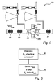
- a received power level P rec of the reflected electromagnetic signals is determined.
- the received power level P rec is typically determined in slightly different ways.
- FMCW frequency modulated continuous wave
- A/D analog-to-digital
- FFT fast fourier transform
- the relevant received signals are discriminated from the rest of the received signals.
- Such discrimination is typically made in software using various more or less elaborate selection criteria. For example, the strongest received echo signal, and/or the first received echo signal may be evaluated. Typically, the entire tank is scanned at an initial stage, and, based on the result of the scan, the correct echo signals (the electromagnetic signals that have been reflected at the surface 5 of the product 6) can be selected. In subsequent measurements, the correct echo signals can be focused on, and not further scan is necessary.
- the correct echo signals the electromagnetic signals that have been reflected at the surface 5 of the product 6
- the transmitted power level Ptrans is controlled to keep the received power level P rec determined in step 51 below a predetermined threshold level P rec,th .
- the transceiver may include more than one signal generator, such as one transmitter oscillator for the transmitter branch, and one receiver oscillator for the receiver branch.
Landscapes
- Physics & Mathematics (AREA)
- Electromagnetism (AREA)
- Thermal Sciences (AREA)
- Fluid Mechanics (AREA)
- General Physics & Mathematics (AREA)
- Measurement Of Levels Of Liquids Or Fluent Solid Materials (AREA)
Claims (15)
- Système indicateur de niveau de radar (1) pour déterminer un niveau de remplissage d'un produit (6) contenu dans un réservoir (2), ledit système indicateur de niveau de remplissage (1) comprenant :un émetteur-récepteur (10) incluant :un générateur de signaux (11) pour générer des signaux électromagnétiques à des fins de transmission ;une branche d'émetteur (13) pour émettre lesdits signaux électromagnétiques ; etune branche de récepteur (14) pour recevoir des signaux électromagnétiques ;ledit système indicateur de niveau de radar (1) comprenant en outre un dispositif de propagation (3) pour permettre aux signaux électromagnétiques transmis de se propager vers une surface (5) dudit produit à l'intérieur du réservoir, où les signaux sont réfléchis, et pour renvoyer les signaux électromagnétiques réfléchis à partir de ladite surface du produit ;des circuits de traitement connectés audit émetteur-récepteur (10) et configurés pour déterminer ledit niveau de remplissage sur la base desdits signaux électromagnétiques réfléchis ;des circuits de détection de puissance connectés audit émetteur-récepteur et configurés pour déterminer un niveau de puissance reçu desdits signaux électromagnétiques reçus ; etdes circuits d'ajustement de niveau de puissance (20) prévus sur ladite branche d'émetteur de l'émetteur-récepteur, connectés auxdits circuits de détermination de puissance, et configurés pour ajuster un niveau de puissance transmis desdits signaux électromagnétiques émis en réponse audit niveau de puissance reçu déterminé des signaux électromagnétiques réfléchis,caractérisé en ce que lesdits circuits d'ajustement de niveau de puissance (20) sont configurés pour ajuster ledit niveau de puissance transmis d'une manière telle que ledit niveau de puissance reçu soit gardé en dessous d'une valeur seuil prédéterminée,ladite valeur seuil prédéterminée étant sélectionnée afin de garder une puissance moyenne temporelle émise par le système indicateur de niveau de radar en dessous d'un niveau de puissance prédéterminé.
- Système indicateur de niveau de radar (1) selon la revendication 1, dans lequel lesdits circuits de détection de puissance sont en outre configurés pour distinguer lesdits signaux électromagnétiques réfléchis, ayant été réfléchis au niveau de ladite surface du produit, et déterminer un niveau de puissance reçu correspondant.
- Système indicateur de niveau de radar (1) selon la revendication 1 ou 2, dans lequel ladite valeur seuil prédéterminée est -60 dBm.
- Système indicateur de niveau de radar (1) selon une quelconque des revendications 1 à 3, dans lequel lesdits circuits d'ajustement de niveau de puissance (20) sont adaptés pour garder un retard de groupe des signaux électromagnétiques passant à travers ceux-ci substantiellement indépendant des conditions environnementales et/ou du point de fonctionnement desdits circuits d'ajustement de niveau de puissance.
- Système indicateur de niveau de radar (1) selon la revendication 4, dans lequel lesdits circuits d'ajustement de niveau de puissance (20) comprennent :un atténuateur réglable (22) pour émettre de manière réglable ledit niveau de puissance émis ;un amplificateur réglable (21) pour amplifier de manière réglable ledit niveau de puissance émis ; etdes circuits de compensation (23) configurés pour compenser les différences dans ledit retard de groupe des signaux électromagnétiques passant à travers lesdits circuits d'ajustement de niveau de puissance.
- Système indicateur de niveau de radar (1) selon la revendication 4 ou 5, dans lequel lesdits circuits d'ajustement de niveau de puissance (20) sont configurés de telle sorte qu'ils aient une petite extension physique telle qu'un retard de groupe desdits signaux électromagnétiques quand ils passent à travers lesdits niveaux d'ajustement de niveau de puissance corresponde à une distance qui est plus courte que ladite longueur d'onde des signaux électromagnétiques.
- Système indicateur de niveau de radar (1) selon une quelconque des revendications 1 à 6, comprenant en outre des circuits de détection de température pour indiquer une température de fonctionnement desdits circuits d'ajustement de niveau de puissance.
- Système indicateur de niveau de radar (1) selon la revendication 7, dans lequel ledit système indicateur de niveau de radar est adapté pour commander les conditions de fonctionnement desdits circuits d'ajustement de niveau de puissance en réponse à ladite température de fonctionnement indiquée, afin de garder un retard de groupe des signaux électromagnétiques passant à travers ceux-ci substantiellement indépendant de la température de fonctionnement.
- Système indicateur de niveau de radar (1) selon une quelconque des revendications 1 à 8, dans lequel lesdits circuits de traitement sont configurés pour ajuster ledit niveau de remplissage déterminé sur la base des paramètres desdits circuits d'ajustement de niveau de puissance et/ou des conditions environnementales, pour compenser les différences de retard de groupe des signaux électromagnétiques passant à travers lesdits circuits d'ajustement de niveau de puissance.
- Système indicateur de niveau de radar (1) selon une quelconque des revendications 1 à 9, comprenant en outre un mélangeur (18) pour mélanger lesdits signaux électromagnétiques reçus avec les signaux indicatifs desdits signaux électromagnétiques émis, pour permettre ainsi une détermination dudit niveau de remplissage sur la base d'une différence entre lesdits signaux électromagnétiques émis et reçus.
- Système indicateur de niveau de radar (1) selon une quelconque des revendications 1 à 10, dans lequel une puissance totale desdits signaux émis, à la suite d'un ajustement de niveau de puissance, est en dessous de -41.3 dBm.
- Système indicateur de niveau multi-radar comprenant une pluralité de systèmes indicateurs de niveau de radar (1) pour déterminer un niveau de remplissage d'un produit contenu dans un réservoir, chaque système indicateur de niveau de radar comprenant :un émetteur-récepteur (10) incluant :un générateur de signaux (11) pour générer des signaux électromagnétiques à des fins de transmission ;une branche d'émetteur (13) pour émettre lesdits signaux électromagnétiques ; etune branche de récepteur (14) pour recevoir des signaux électromagnétiques ;ledit système indicateur de niveau de radar (1) comprenant en outre un dispositif de propagation pour permettre aux signaux électromagnétiques transmis de se propager vers une surface dudit produit à l'intérieur du réservoir, où les signaux sont réfléchis, et pour renvoyer les signaux électromagnétiques réfléchis à partir de ladite surface du produit ;des circuits de traitement connectés audit émetteur-récepteur (10) et configurés pour déterminer ledit niveau de remplissage sur la base desdits signaux électromagnétiques réfléchis ;des circuits de détection de puissance connectés audit émetteur-récepteur et configurés pour déterminer un niveau de puissance reçu desdits signaux électromagnétiques reçus ; etdes circuits d'ajustement de niveau de puissance (20) fournis sur ladite branche d'émetteur de l'émetteur-récepteur, connectés auxdits circuits de détermination de puissance, et configurés pour ajuster un niveau de puissance transmis desdits signaux électromagnétiques émis en réponse audit niveau de puissance reçu déterminé des signaux électromagnétiques réfléchis,caractérisé en ce que lesdits circuits d'ajustement de niveau de puissance (20) sont configurés pour ajuster ledit niveau de puissance transmis d'une manière telle que ledit niveau de puissance reçu soit gardé en dessous d'une valeur seuil prédéterminée,ladite valeur seuil prédéterminée étant sélectionnée afin de garder une puissance moyenne temporelle émise par le système indicateur de niveau de radar en dessous d'un niveau de puissance prédéterminé.
- Procédé de contrôle adaptatif d'une puissance de transmission d'un système indicateur de niveau de radar comprenant :un émetteur-récepteur incluant :un générateur de signaux pour générer des signaux électromagnétiques à des fins de transmission ;une branche d'émetteur pour émettre lesdits signaux électromagnétiques ; etune branche de récepteur pour recevoir des signaux électromagnétiques ;un dispositif de propagation pour permettre aux signaux électromagnétiques émis de se propager vers ne surface dudit produit à l'intérieur du réservoir, où les signaux sont réfléchis, et pour renvoyer les signaux électromagnétiques réfléchis depuis ladite surface du produit ;des circuits de traitement connectés audit émetteur-récepteur et configurés pour déterminer ledit niveau de remplissage sur la base desdits signaux électromagnétiques réfléchis,ledit procédé comprenant les étapes consistant à :déterminer (61) un niveau de puissance reçu desdits signaux électromagnétiques réfléchis ; etcommander (62) un niveau de puissance transmise desdits signaux électromagnétiques émis,caractérisé en ce que ledit niveau de puissance émis des signaux électromagnétiques émis est régulé de telle sorte que ledit niveau de puissance reçu soit gardé en dessous d'une valeur seuil prédéterminée,ladite valeur seuil prédéterminée étant sélectionnée afin de garder une puissance moyenne temporelle émise par le système indicateur de niveau de radar en dessous d'un niveau de puissance prédéterminé.
- Procédé selon la revendication 13, comprenant en outre l'étape consistant à :distinguer lesdits signaux électromagnétiques renvoyés, ayant été réfléchis au niveau de ladite surface du produit.
- Procédé selon la revendication 13 ou 14, comprenant en outre l'étape consistant à :ajuster des propriétés de propagation de signal dudit système indicateur de niveau de radar afin de garder un retard de groupe des signaux électromagnétiques passant à travers ladite branche d'émetteur essentiellement constant.
Applications Claiming Priority (2)
| Application Number | Priority Date | Filing Date | Title |
|---|---|---|---|
| SE0701228 | 2007-05-16 | ||
| US11/807,984 US7895889B2 (en) | 2007-05-16 | 2007-05-31 | Radar level gauge system with adaptive transmission power control |
Publications (3)
| Publication Number | Publication Date |
|---|---|
| EP1992923A2 EP1992923A2 (fr) | 2008-11-19 |
| EP1992923A3 EP1992923A3 (fr) | 2009-07-22 |
| EP1992923B1 true EP1992923B1 (fr) | 2012-07-11 |
Family
ID=39488241
Family Applications (1)
| Application Number | Title | Priority Date | Filing Date |
|---|---|---|---|
| EP20080156278 Not-in-force EP1992923B1 (fr) | 2007-05-16 | 2008-05-15 | Système indicateur de niveau de radar avec contrôle de puissance de transmission adaptatif |
Country Status (2)
| Country | Link |
|---|---|
| EP (1) | EP1992923B1 (fr) |
| WO (1) | WO2008140412A1 (fr) |
Cited By (1)
| Publication number | Priority date | Publication date | Assignee | Title |
|---|---|---|---|---|
| US11231492B2 (en) * | 2017-07-25 | 2022-01-25 | Vega Grieshaber Kg | Radar fill level measurement device and method for operating a radar fill level measurement device |
Families Citing this family (4)
| Publication number | Priority date | Publication date | Assignee | Title |
|---|---|---|---|---|
| EP2161551A1 (fr) | 2008-09-04 | 2010-03-10 | VEGA Grieshaber KG | Puissance d'émission variable pour la mesure du niveau de remplissage |
| US11029187B2 (en) | 2017-06-21 | 2021-06-08 | Vega Grieshaber Kg | Fill level reflectometer having a variable measurement sequence |
| HUE060367T2 (hu) * | 2017-06-21 | 2023-02-28 | Grieshaber Vega Kg | Szintradar eszköz vezérelt adóteljesítménnyel |
| EP4462150A1 (fr) * | 2023-05-12 | 2024-11-13 | Nxp B.V. | Procédé de fonctionnement d'un système radar |
Family Cites Families (4)
| Publication number | Priority date | Publication date | Assignee | Title |
|---|---|---|---|---|
| DE10039943A1 (de) * | 2000-08-16 | 2002-02-28 | Adc Automotive Dist Control | Verfahren zum Betreiben eines Radarsystems |
| EP1785699B1 (fr) * | 2005-11-09 | 2012-06-27 | Siemens Aktiengesellschaft | Système de détection de niveau de liquide par echos d'impulsions |
| US7363812B2 (en) * | 2005-11-09 | 2008-04-29 | Rosemount Tank Radar Ab | Radar level gauge with variable transmission power |
| DE102005057094B4 (de) * | 2005-11-30 | 2013-02-14 | Vega Grieshaber Kg | Füllstandradar mit variabler Sendeleistung |
-
2008
- 2008-05-15 EP EP20080156278 patent/EP1992923B1/fr not_active Not-in-force
- 2008-05-15 WO PCT/SE2008/050573 patent/WO2008140412A1/fr not_active Ceased
Cited By (1)
| Publication number | Priority date | Publication date | Assignee | Title |
|---|---|---|---|---|
| US11231492B2 (en) * | 2017-07-25 | 2022-01-25 | Vega Grieshaber Kg | Radar fill level measurement device and method for operating a radar fill level measurement device |
Also Published As
| Publication number | Publication date |
|---|---|
| EP1992923A3 (fr) | 2009-07-22 |
| EP1992923A2 (fr) | 2008-11-19 |
| WO2008140412A1 (fr) | 2008-11-20 |
Similar Documents
| Publication | Publication Date | Title |
|---|---|---|
| US7895889B2 (en) | Radar level gauge system with adaptive transmission power control | |
| US7482971B2 (en) | Time-of-flight-ranging system and method for calibrating such a system | |
| US10613198B2 (en) | System and method for testing integrated radar systems | |
| US8915133B2 (en) | Arrangement and method for testing a level gauge system | |
| US9329073B2 (en) | Adaptive radar system with mutliple waveforms | |
| EP3077777B1 (fr) | Radar à impulsion multimode fournissant une commande de signal d'impulsion à transmission automatique | |
| US9612147B2 (en) | Radar level gauge system with multiple receiver branches | |
| EP1992923B1 (fr) | Système indicateur de niveau de radar avec contrôle de puissance de transmission adaptatif | |
| US20080024145A1 (en) | Independent Reference Pulse Generation | |
| CN109579946B (zh) | 用于确定过程变量的方法和雷达料位计 | |
| US20070249314A1 (en) | Adjusting parameters associated with transmitter leakage | |
| US20090033543A1 (en) | Radar level gauge with variable pulse parameters | |
| US7542866B1 (en) | Threshold setting for a radar level transmitter | |
| US10801873B2 (en) | System and method for determining level and density distribution | |
| US8069721B2 (en) | Radar level gauge system having limited transmission power | |
| US6677891B2 (en) | Method and device for transmitting and receiving electromagnetic waves | |
| US20060000275A1 (en) | Radar level gauge system with intermittent amplification | |
| US7098843B2 (en) | Automatic sensitivity control for radar level gauges | |
| US7639176B2 (en) | Reference pulse generation | |
| EP1992922B1 (fr) | Système indicateur de niveau de radar doté d'une puissance de transmission limitée | |
| WO2002025227A1 (fr) | Reglage de seuil ameliore pour emetteur de niveau radar | |
| US10209118B2 (en) | Radar level gauge system and method with signal propagation path modeling | |
| CN117724095A (zh) | 一种星载Ka频段自适应水汽补偿成像方法 | |
| CN120275910A (zh) | 一种干扰信号消除方法、设备及装置 | |
| JPH04203992A (ja) | 能動型マイクロ波後方散乱装置 |
Legal Events
| Date | Code | Title | Description |
|---|---|---|---|
| PUAI | Public reference made under article 153(3) epc to a published international application that has entered the european phase |
Free format text: ORIGINAL CODE: 0009012 |
|
| AK | Designated contracting states |
Kind code of ref document: A2 Designated state(s): AT BE BG CH CY CZ DE DK EE ES FI FR GB GR HR HU IE IS IT LI LT LU LV MC MT NL NO PL PT RO SE SI SK TR |
|
| AX | Request for extension of the european patent |
Extension state: AL BA MK RS |
|
| PUAL | Search report despatched |
Free format text: ORIGINAL CODE: 0009013 |
|
| AK | Designated contracting states |
Kind code of ref document: A3 Designated state(s): AT BE BG CH CY CZ DE DK EE ES FI FR GB GR HR HU IE IS IT LI LT LU LV MC MT NL NO PL PT RO SE SI SK TR |
|
| AX | Request for extension of the european patent |
Extension state: AL BA MK RS |
|
| 17P | Request for examination filed |
Effective date: 20100111 |
|
| 17Q | First examination report despatched |
Effective date: 20100301 |
|
| AKX | Designation fees paid |
Designated state(s): AT BE BG CH CY CZ DE DK EE ES FI FR GB GR HR HU IE IS IT LI LT LU LV MC MT NL NO PL PT RO SE SI SK TR |
|
| RIC1 | Information provided on ipc code assigned before grant |
Ipc: G01F 23/284 20060101AFI20110708BHEP |
|
| GRAP | Despatch of communication of intention to grant a patent |
Free format text: ORIGINAL CODE: EPIDOSNIGR1 |
|
| GRAC | Information related to communication of intention to grant a patent modified |
Free format text: ORIGINAL CODE: EPIDOSCIGR1 |
|
| GRAS | Grant fee paid |
Free format text: ORIGINAL CODE: EPIDOSNIGR3 |
|
| GRAA | (expected) grant |
Free format text: ORIGINAL CODE: 0009210 |
|
| AK | Designated contracting states |
Kind code of ref document: B1 Designated state(s): AT BE BG CH CY CZ DE DK EE ES FI FR GB GR HR HU IE IS IT LI LT LU LV MC MT NL NO PL PT RO SE SI SK TR |
|
| REG | Reference to a national code |
Ref country code: GB Ref legal event code: FG4D |
|
| REG | Reference to a national code |
Ref country code: CH Ref legal event code: EP |
|
| REG | Reference to a national code |
Ref country code: AT Ref legal event code: REF Ref document number: 566366 Country of ref document: AT Kind code of ref document: T Effective date: 20120715 |
|
| REG | Reference to a national code |
Ref country code: IE Ref legal event code: FG4D |
|
| REG | Reference to a national code |
Ref country code: DE Ref legal event code: R096 Ref document number: 602008017063 Country of ref document: DE Effective date: 20120906 |
|
| REG | Reference to a national code |
Ref country code: NL Ref legal event code: T3 |
|
| REG | Reference to a national code |
Ref country code: AT Ref legal event code: MK05 Ref document number: 566366 Country of ref document: AT Kind code of ref document: T Effective date: 20120711 |
|
| REG | Reference to a national code |
Ref country code: LT Ref legal event code: MG4D Effective date: 20120711 |
|
| PG25 | Lapsed in a contracting state [announced via postgrant information from national office to epo] |
Ref country code: NO Free format text: LAPSE BECAUSE OF FAILURE TO SUBMIT A TRANSLATION OF THE DESCRIPTION OR TO PAY THE FEE WITHIN THE PRESCRIBED TIME-LIMIT Effective date: 20121011 Ref country code: BE Free format text: LAPSE BECAUSE OF FAILURE TO SUBMIT A TRANSLATION OF THE DESCRIPTION OR TO PAY THE FEE WITHIN THE PRESCRIBED TIME-LIMIT Effective date: 20120711 Ref country code: HR Free format text: LAPSE BECAUSE OF FAILURE TO SUBMIT A TRANSLATION OF THE DESCRIPTION OR TO PAY THE FEE WITHIN THE PRESCRIBED TIME-LIMIT Effective date: 20120711 Ref country code: AT Free format text: LAPSE BECAUSE OF FAILURE TO SUBMIT A TRANSLATION OF THE DESCRIPTION OR TO PAY THE FEE WITHIN THE PRESCRIBED TIME-LIMIT Effective date: 20120711 Ref country code: IS Free format text: LAPSE BECAUSE OF FAILURE TO SUBMIT A TRANSLATION OF THE DESCRIPTION OR TO PAY THE FEE WITHIN THE PRESCRIBED TIME-LIMIT Effective date: 20121111 Ref country code: LT Free format text: LAPSE BECAUSE OF FAILURE TO SUBMIT A TRANSLATION OF THE DESCRIPTION OR TO PAY THE FEE WITHIN THE PRESCRIBED TIME-LIMIT Effective date: 20120711 Ref country code: FI Free format text: LAPSE BECAUSE OF FAILURE TO SUBMIT A TRANSLATION OF THE DESCRIPTION OR TO PAY THE FEE WITHIN THE PRESCRIBED TIME-LIMIT Effective date: 20120711 Ref country code: CY Free format text: LAPSE BECAUSE OF FAILURE TO SUBMIT A TRANSLATION OF THE DESCRIPTION OR TO PAY THE FEE WITHIN THE PRESCRIBED TIME-LIMIT Effective date: 20120711 |
|
| PG25 | Lapsed in a contracting state [announced via postgrant information from national office to epo] |
Ref country code: LV Free format text: LAPSE BECAUSE OF FAILURE TO SUBMIT A TRANSLATION OF THE DESCRIPTION OR TO PAY THE FEE WITHIN THE PRESCRIBED TIME-LIMIT Effective date: 20120711 Ref country code: PT Free format text: LAPSE BECAUSE OF FAILURE TO SUBMIT A TRANSLATION OF THE DESCRIPTION OR TO PAY THE FEE WITHIN THE PRESCRIBED TIME-LIMIT Effective date: 20121112 Ref country code: SI Free format text: LAPSE BECAUSE OF FAILURE TO SUBMIT A TRANSLATION OF THE DESCRIPTION OR TO PAY THE FEE WITHIN THE PRESCRIBED TIME-LIMIT Effective date: 20120711 Ref country code: PL Free format text: LAPSE BECAUSE OF FAILURE TO SUBMIT A TRANSLATION OF THE DESCRIPTION OR TO PAY THE FEE WITHIN THE PRESCRIBED TIME-LIMIT Effective date: 20120711 Ref country code: SE Free format text: LAPSE BECAUSE OF FAILURE TO SUBMIT A TRANSLATION OF THE DESCRIPTION OR TO PAY THE FEE WITHIN THE PRESCRIBED TIME-LIMIT Effective date: 20120711 Ref country code: GR Free format text: LAPSE BECAUSE OF FAILURE TO SUBMIT A TRANSLATION OF THE DESCRIPTION OR TO PAY THE FEE WITHIN THE PRESCRIBED TIME-LIMIT Effective date: 20121012 |
|
| PG25 | Lapsed in a contracting state [announced via postgrant information from national office to epo] |
Ref country code: RO Free format text: LAPSE BECAUSE OF FAILURE TO SUBMIT A TRANSLATION OF THE DESCRIPTION OR TO PAY THE FEE WITHIN THE PRESCRIBED TIME-LIMIT Effective date: 20120711 Ref country code: CZ Free format text: LAPSE BECAUSE OF FAILURE TO SUBMIT A TRANSLATION OF THE DESCRIPTION OR TO PAY THE FEE WITHIN THE PRESCRIBED TIME-LIMIT Effective date: 20120711 Ref country code: ES Free format text: LAPSE BECAUSE OF FAILURE TO SUBMIT A TRANSLATION OF THE DESCRIPTION OR TO PAY THE FEE WITHIN THE PRESCRIBED TIME-LIMIT Effective date: 20121022 Ref country code: DK Free format text: LAPSE BECAUSE OF FAILURE TO SUBMIT A TRANSLATION OF THE DESCRIPTION OR TO PAY THE FEE WITHIN THE PRESCRIBED TIME-LIMIT Effective date: 20120711 Ref country code: EE Free format text: LAPSE BECAUSE OF FAILURE TO SUBMIT A TRANSLATION OF THE DESCRIPTION OR TO PAY THE FEE WITHIN THE PRESCRIBED TIME-LIMIT Effective date: 20120711 |
|
| PLBE | No opposition filed within time limit |
Free format text: ORIGINAL CODE: 0009261 |
|
| STAA | Information on the status of an ep patent application or granted ep patent |
Free format text: STATUS: NO OPPOSITION FILED WITHIN TIME LIMIT |
|
| PG25 | Lapsed in a contracting state [announced via postgrant information from national office to epo] |
Ref country code: IT Free format text: LAPSE BECAUSE OF FAILURE TO SUBMIT A TRANSLATION OF THE DESCRIPTION OR TO PAY THE FEE WITHIN THE PRESCRIBED TIME-LIMIT Effective date: 20120711 Ref country code: SK Free format text: LAPSE BECAUSE OF FAILURE TO SUBMIT A TRANSLATION OF THE DESCRIPTION OR TO PAY THE FEE WITHIN THE PRESCRIBED TIME-LIMIT Effective date: 20120711 |
|
| 26N | No opposition filed |
Effective date: 20130412 |
|
| PG25 | Lapsed in a contracting state [announced via postgrant information from national office to epo] |
Ref country code: BG Free format text: LAPSE BECAUSE OF FAILURE TO SUBMIT A TRANSLATION OF THE DESCRIPTION OR TO PAY THE FEE WITHIN THE PRESCRIBED TIME-LIMIT Effective date: 20121011 |
|
| REG | Reference to a national code |
Ref country code: DE Ref legal event code: R097 Ref document number: 602008017063 Country of ref document: DE Effective date: 20130412 |
|
| PG25 | Lapsed in a contracting state [announced via postgrant information from national office to epo] |
Ref country code: MC Free format text: LAPSE BECAUSE OF FAILURE TO SUBMIT A TRANSLATION OF THE DESCRIPTION OR TO PAY THE FEE WITHIN THE PRESCRIBED TIME-LIMIT Effective date: 20120711 |
|
| REG | Reference to a national code |
Ref country code: CH Ref legal event code: PL |
|
| GBPC | Gb: european patent ceased through non-payment of renewal fee |
Effective date: 20130515 |
|
| PG25 | Lapsed in a contracting state [announced via postgrant information from national office to epo] |
Ref country code: CH Free format text: LAPSE BECAUSE OF NON-PAYMENT OF DUE FEES Effective date: 20130531 Ref country code: LI Free format text: LAPSE BECAUSE OF NON-PAYMENT OF DUE FEES Effective date: 20130531 |
|
| REG | Reference to a national code |
Ref country code: IE Ref legal event code: MM4A |
|
| PG25 | Lapsed in a contracting state [announced via postgrant information from national office to epo] |
Ref country code: IE Free format text: LAPSE BECAUSE OF NON-PAYMENT OF DUE FEES Effective date: 20130515 Ref country code: GB Free format text: LAPSE BECAUSE OF NON-PAYMENT OF DUE FEES Effective date: 20130515 |
|
| PG25 | Lapsed in a contracting state [announced via postgrant information from national office to epo] |
Ref country code: MT Free format text: LAPSE BECAUSE OF FAILURE TO SUBMIT A TRANSLATION OF THE DESCRIPTION OR TO PAY THE FEE WITHIN THE PRESCRIBED TIME-LIMIT Effective date: 20120711 |
|
| PG25 | Lapsed in a contracting state [announced via postgrant information from national office to epo] |
Ref country code: TR Free format text: LAPSE BECAUSE OF FAILURE TO SUBMIT A TRANSLATION OF THE DESCRIPTION OR TO PAY THE FEE WITHIN THE PRESCRIBED TIME-LIMIT Effective date: 20120711 |
|
| PG25 | Lapsed in a contracting state [announced via postgrant information from national office to epo] |
Ref country code: LU Free format text: LAPSE BECAUSE OF NON-PAYMENT OF DUE FEES Effective date: 20130515 Ref country code: HU Free format text: LAPSE BECAUSE OF FAILURE TO SUBMIT A TRANSLATION OF THE DESCRIPTION OR TO PAY THE FEE WITHIN THE PRESCRIBED TIME-LIMIT; INVALID AB INITIO Effective date: 20080515 |
|
| REG | Reference to a national code |
Ref country code: FR Ref legal event code: PLFP Year of fee payment: 9 |
|
| REG | Reference to a national code |
Ref country code: FR Ref legal event code: PLFP Year of fee payment: 10 |
|
| REG | Reference to a national code |
Ref country code: FR Ref legal event code: PLFP Year of fee payment: 11 |
|
| PGFP | Annual fee paid to national office [announced via postgrant information from national office to epo] |
Ref country code: NL Payment date: 20220420 Year of fee payment: 15 |
|
| PGFP | Annual fee paid to national office [announced via postgrant information from national office to epo] |
Ref country code: FR Payment date: 20220421 Year of fee payment: 15 Ref country code: DE Payment date: 20220420 Year of fee payment: 15 |
|
| REG | Reference to a national code |
Ref country code: DE Ref legal event code: R119 Ref document number: 602008017063 Country of ref document: DE |
|
| REG | Reference to a national code |
Ref country code: NL Ref legal event code: MM Effective date: 20230601 |
|
| PG25 | Lapsed in a contracting state [announced via postgrant information from national office to epo] |
Ref country code: NL Free format text: LAPSE BECAUSE OF NON-PAYMENT OF DUE FEES Effective date: 20230601 |
|
| PG25 | Lapsed in a contracting state [announced via postgrant information from national office to epo] |
Ref country code: DE Free format text: LAPSE BECAUSE OF NON-PAYMENT OF DUE FEES Effective date: 20231201 |
|
| PG25 | Lapsed in a contracting state [announced via postgrant information from national office to epo] |
Ref country code: FR Free format text: LAPSE BECAUSE OF NON-PAYMENT OF DUE FEES Effective date: 20230531 |