EP1992964B1 - Procédé pour la réduction d'erreurs dans une télémétrie bidirectionnelle entre deux émetteurs-récepteurs dus à un décalage de la fréquence de l'horloge - Google Patents
Procédé pour la réduction d'erreurs dans une télémétrie bidirectionnelle entre deux émetteurs-récepteurs dus à un décalage de la fréquence de l'horloge Download PDFInfo
- Publication number
- EP1992964B1 EP1992964B1 EP08251001A EP08251001A EP1992964B1 EP 1992964 B1 EP1992964 B1 EP 1992964B1 EP 08251001 A EP08251001 A EP 08251001A EP 08251001 A EP08251001 A EP 08251001A EP 1992964 B1 EP1992964 B1 EP 1992964B1
- Authority
- EP
- European Patent Office
- Prior art keywords
- frame
- transceiver
- time
- reply
- request
- Prior art date
- Legal status (The legal status is an assumption and is not a legal conclusion. Google has not performed a legal analysis and makes no representation as to the accuracy of the status listed.)
- Active
Links
Images



Classifications
-
- G—PHYSICS
- G01—MEASURING; TESTING
- G01S—RADIO DIRECTION-FINDING; RADIO NAVIGATION; DETERMINING DISTANCE OR VELOCITY BY USE OF RADIO WAVES; LOCATING OR PRESENCE-DETECTING BY USE OF THE REFLECTION OR RERADIATION OF RADIO WAVES; ANALOGOUS ARRANGEMENTS USING OTHER WAVES
- G01S13/00—Systems using the reflection or reradiation of radio waves, e.g. radar systems; Analogous systems using reflection or reradiation of waves whose nature or wavelength is irrelevant or unspecified
- G01S13/74—Systems using reradiation of radio waves, e.g. secondary radar systems; Analogous systems
- G01S13/82—Systems using reradiation of radio waves, e.g. secondary radar systems; Analogous systems wherein continuous-type signals are transmitted
- G01S13/825—Systems using reradiation of radio waves, e.g. secondary radar systems; Analogous systems wherein continuous-type signals are transmitted with exchange of information between interrogator and responder
-
- G—PHYSICS
- G01—MEASURING; TESTING
- G01S—RADIO DIRECTION-FINDING; RADIO NAVIGATION; DETERMINING DISTANCE OR VELOCITY BY USE OF RADIO WAVES; LOCATING OR PRESENCE-DETECTING BY USE OF THE REFLECTION OR RERADIATION OF RADIO WAVES; ANALOGOUS ARRANGEMENTS USING OTHER WAVES
- G01S13/00—Systems using the reflection or reradiation of radio waves, e.g. radar systems; Analogous systems using reflection or reradiation of waves whose nature or wavelength is irrelevant or unspecified
- G01S13/74—Systems using reradiation of radio waves, e.g. secondary radar systems; Analogous systems
-
- G—PHYSICS
- G01—MEASURING; TESTING
- G01S—RADIO DIRECTION-FINDING; RADIO NAVIGATION; DETERMINING DISTANCE OR VELOCITY BY USE OF RADIO WAVES; LOCATING OR PRESENCE-DETECTING BY USE OF THE REFLECTION OR RERADIATION OF RADIO WAVES; ANALOGOUS ARRANGEMENTS USING OTHER WAVES
- G01S7/00—Details of systems according to groups G01S13/00, G01S15/00, G01S17/00
- G01S7/02—Details of systems according to groups G01S13/00, G01S15/00, G01S17/00 of systems according to group G01S13/00
- G01S7/40—Means for monitoring or calibrating
Definitions
- the present invention relates generally to radio communication systems, and more particularly to determining distances between transceivers using two-way ranging, which is known as radio ranging.
- a conventional communication frame 100 for a wireless network includes as fields: a preamble 110, a start of frame delimiter (SFD) 120, a physical layer header (PHY) 130, and a physical layer sevice data unit (PSDU) 140.
- SFD start of frame delimiter
- PHY physical layer header
- PSDU physical layer sevice data unit
- the PSDU typically includes a payload, see IEEE 802.15.4a-D7 standard, November 2006.
- the preamble 110 can be used for acquisition and ranging.
- the SFD 120 is used for frame synchronization.
- the detection of the SFD indicates the beginning of the PHY 130 and the PSDU 140.
- the frame 100 has a time duration of T1 160, and a time duration of the PHY and PSDU is T2 150.
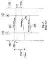
- Figure 2 shows a conventional ranging method.
- the first transceiver A 210 transmits 201 a request frame to the second transceiver B 220.
- Figure 2 also shows a time axis 240 for the transceiver A and a time axis 250 for the transceiver B 220.
- the transceiver A 210 records a time t 1 that the request frame was transmitted according to a clock of the transceiver A 210.
- the transceiver B 220 Upon receiving the request frame, the transceiver B 220 transmits 202 a reply frame to the transceiver A 210.
- the transceiver A 210 measures the time of arrival (TOA) t 2 of the reply frame according to its clock.
- TOA time of arrival
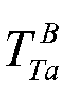
- a delay at the transceiver B 220 between receiving the request frame and transmitting the reply frame is T ta B 250.
- the transceiver B 220 transmits 205 the delay 250 to the transceiver A 210 in a timestamp report.
- An estimate of the distance D between the transceiver A 210 and the transceiver B 220 is the time for the round trip T round A 270 minus the delay at the transceiver B 220 divided by two and multiplied by the speed of light.
- the conventional method as specified in method in the IEEE 802.15.4a Standard Draft 7 does not address errors due to a frequency offset between the clocks of the transceivers. Indeed, in practical applications, the measurements of T round A and T ta B are different from their true value due to the frequency offset.
- the clock tolerance of the transceiver A 210 is e A
- the clock tolerance of the transceiver B 220 as e B .
- T ⁇ 1 T round A ⁇ 1 + e A - T ta B ⁇ 1 + e B 2 .
- Equation (4) approximates to e tw ⁇ T ta B ⁇ e A + e B .
- US 6,107,959 discloses a system and method for determining the position of a user terminal in a low-Earth orbit satellite communications system.
- the invention provides a method for reducing ranging errors due to a clock frequency offset in two-way ranging between radio transceivers, which minimizes impacts of clock frequency offsets on range estimation between two devices using two-way time of arrival measurements.
- a first transceiver measures a time CA1 between transmitting a request frame and receiving a reply frame, and a time CA2 between receiving a first information bit of the reply frame and receiving a last information bit of the reply frame.
- a second transceiver measures a time C B 2 between receiving the request frame and transmitting the last information bit of the reply frame, and a time C B 1 between receiving a first information bit of the request frame and a last information bit of the request frame.
- the embodiments of my invention provide two-way ranging methods for estimating a distance between a first transceiver A and a second transceiver B in a wireless communications network.
- the method reduces errors due to frequency offsets in clocks of the transceivers.
- a request frame 300 includes as fields: a preamble 301, a start of frame delimiter (SFD) 302, a physical layer header (PHY) 303, and request physical layer service data unit (PSDU request ) 304.
- the PHY 303 and PSDU request 304 can carry data or information bits of the request frame 300.
- a time duration of the data or information bit fields 303 and 304 is denoted by T frame1 350.
- a reply frame 400 includes the preamble 301, the start of frame delimiter (SFD) 302, a physical layer header (PHY) 403 and a reply physical layer service data unit (PSDU reply ) 404.
- SFD start of frame delimiter
- PHY physical layer header
- PSDU reply reply physical layer service data unit
- a time duration of the data or information bit fields 403 and 404 of the reply frame is T frame2 450.
- T frame1 350 and T frame2 450 for the information bits can be different. However, for simplicity of this description, the duration for both T frame1 350 and T frame2 450 can be generally denoted by T frame .
- FIG 5 shows a timing diagram of a ranging method according to an embodiment of the invention.
- the block diagram of the method is shown in Figure 6 .
- Figure 7 shows the method steps.
- the transceiver A 510 includes a transmit clock 511
- the transceiver B 520 includes a receive clock B 512.
- An ideal clock period (cycle) is T i .
- the clock period is determined by a frequency of a crystal of the clock.
- the ideal clock frequency is specified by the manufacturer. In real systems, however, the clock frequency can be offset from the ideal frequency due to, e.g., manufacturing inconsistencies or environmental conditions. Therefore, the actual clock period of the transceiver A 510 is T a , and the actual clock period of the transceiver B 520 is T b . It is desired to minimize errors due to this frequency offset.
- a transceiver A 510 transmits the request frame, see inset 300 for start and end of frame fields, to a transceiver B 520.
- Transceiver A 510 starts 740 a first transmit counter A 1 when the SFD 302 of the request frame 300 is emitted by an antenna 700 of the first transceiver.
- the request frame is received in the second transceiver B 520.
- Transceiver B 520 starts 770 first and second receive counters B 1 and B 2 when detecting the end of the SFD 302 of the request frame 300 at the antenna 720 of the second transceiver B 520.
- Transceiver B 520 stops 730 its first receive counter B, when receiving a last information bit of the request frame 300, which is at the end of the request PSDU 304.
- Transceiver B 520 determines a difference between the start and stop values of the first receive counter B 1 .
- the transceiver B 520 prepares the reply frame 400 and transmits the reply frame to transceiver A 510.
- Transceiver B 520 stops 760 the second receive counter B 2 when the end of the SFD 302 of the reply frame 400 is emitted by its antenna 720.
- transceiver A 510 stops its first transmit counter A 1 and starts a second transmit counter A 2 when it detects the end of the SFD 302 of the received reply frame 400.
- Transceiver A 510 stops 780 the second transmit counter A 2 when it receives the last bit of the PSDU reply 404 of the received reply frame 400 at the antenna 700.
- Transceiver B 520 transmits the counter values C B 1 703 and C B 2 704 to transceiver A 510 in a timestamp report 500.
- Transceiver A 510 divides C B 2 704 by the correction factor ⁇ c 705 to obtain an estimate ⁇ B 2 707.
- T i 706 is known to both transceivers, e.g., it is the time specified by the manufacturer.
- a ranging system has the following example values:
- the embodiments of the invention provide a method for reducing ranging errors due to the effect of clock frequency offsets between clocks of two transceivers.
- a transceiver clock frequency can differ from its ideal clock frequency as specified by the manufacturer due to any of a number of conditions, including but not limited to uncontrollable fabrication processes and environmental conditions. If two transceivers 510 and 520 are performing ranging, the transceivers can have different clock periods or frequencies.
- a one nanosecond timing error causes a 30 cm range error. Therefore, an accurate measurement of time is important for precision ranging in the order of centimeters.
- each transceiver uses two counters or two instants of a single counter to measure various time periods as described below and shown in the Figures.
- the first transceiver 510 measures the number of clock cycles or periods, that is, timing information C A 1 701, between the transmission of the request frame 300 and the reception of the reply frame 400.
- the first transceiver 510 also measures the number of clock cycles between the reception of the first data or information bit of the reply frame, i.e., the beginning of PHY header, and the last information bit of the reply frame, i.e., at the end of data payload of the PSDU reply .
- This counter value is denoted as C A 2 702.
- the responding second transceiver 520 measures the number of clock cycles between the reception of the request frame and the completion of transmission of the reply frame. This counter value is denoted as C B 2 704.
- the second transceiver 520 also measures the number of cycles between the reception of the first information bit of the request frame, i.e., the beginning of PHY header, and the last information bit of the request frame, i.e., the end of the data payload of the PSDU request .
- This counter value is denoted as C B 1 703.
- the second transceiver 520 transmits C B 1 and C B 2 to the first transceiver 510.
- This time of flight corresponds to the range or distance between the two transceivers.
- the first transceiver could transmit its timing information to the second receiver, in which the second transceiver can perform the ranging.
Landscapes
- Engineering & Computer Science (AREA)
- Radar, Positioning & Navigation (AREA)
- Remote Sensing (AREA)
- Computer Networks & Wireless Communication (AREA)
- Physics & Mathematics (AREA)
- General Physics & Mathematics (AREA)
- Radar Systems Or Details Thereof (AREA)
- Synchronisation In Digital Transmission Systems (AREA)
Claims (12)
- Procédé de réduction d'erreurs dans une télémétrie bidirectionnelle entre deux émetteurs-récepteurs, dues à un décalage de la fréquence de l'horloge, comprenant :la mesure (740, 750, 780), dans un premier émetteur-récepteur (510) du temps CA1 entre la transmission d'une trame de demande (300) et la réception d'une trame de réponse (400), et du temps CA2 entre la réception d'un premier bit d'information de la trame de réponse et la réception d'un dernier bit d'information de la trame de réponse ;la mesure (730, 760, 770) dans un deuxième émetteur-récepteur (520) du temps CB2 entre la réception de la trame de demande et la transmission du dernier bit d'information de la trame de réponse, et du temps CB1 entre la réception d'un premier bit d'information de la trame de demande et d'un dernier bit d'information de la trame de demande ;l'application d'un facteur de correction

 la détermination d'un temps de parcours unidirectionnel conformément à
- Procédé selon la revendication 1, dans lequel la période prédéfinie ou prédéterminée Ti est connue des premier et deuxième émetteurs-récepteurs.
- Procédé selon la revendication 1 ou 2, dans lequel les horloges des premier et deuxième émetteurs-récepteurs présentent un décalage de fréquence.
- Procédé selon la revendication 1, 2 ou 3, dans lequel la trame de demande comporte un préambule (301), un délimiteur de début de trame SFD (302), un en-tête de couche physique PHY (303) et une unité de données de service de couche physique PSDUrequest (304), et dans lequel la durée de SFD et de PSDUrequest est de Tframei, et la trame de réponse comporte le préambule, le délimiteur de début de trame (SFD), l'en-tête de couche physique PHY et une unité de données de service de couche physique de réponse PSDUreply (404), et dans lequel la durée de SFD et de PSDUreply est de Tframe2.
- Procédé selon la revendication 4, dans lequel les durées Tframe1 et Tframe2 sont différentes.
- Procédé selon l'une quelconque des revendications 4 à 5, dans lequel

- Procédé selon la revendication 6, dans lequel

- Procédé selon la revendication 7, dans lequel

- Procédé selon la revendication 6, 7 ou 8, dans lequel

- Procédé selon l'une quelconque des revendications 4 à 9, dans lequel PHY et PSDU transportent des bits d'information.
- Procédé selon l'une quelconque des revendications 1 à 10, comprenant en outre :la transmission de CB1 et CB2 au premier émetteur-récepteur dans un rapport d'horodatage.
- Programme informatique, comprenant un moyen de code de programme qui, lorsqu'il est exécuté sur un système informatique, ordonne au système d'informatique d'exécuter le procédé selon l'une quelconque des revendications précédentes.
Applications Claiming Priority (1)
| Application Number | Priority Date | Filing Date | Title |
|---|---|---|---|
| US11/749,517 US7463194B1 (en) | 2007-05-16 | 2007-05-16 | Method for reducing radio ranging errors due to clock frequency offsets |
Publications (3)
| Publication Number | Publication Date |
|---|---|
| EP1992964A2 EP1992964A2 (fr) | 2008-11-19 |
| EP1992964A3 EP1992964A3 (fr) | 2011-02-09 |
| EP1992964B1 true EP1992964B1 (fr) | 2012-06-20 |
Family
ID=39720622
Family Applications (1)
| Application Number | Title | Priority Date | Filing Date |
|---|---|---|---|
| EP08251001A Active EP1992964B1 (fr) | 2007-05-16 | 2008-03-20 | Procédé pour la réduction d'erreurs dans une télémétrie bidirectionnelle entre deux émetteurs-récepteurs dus à un décalage de la fréquence de l'horloge |
Country Status (3)
| Country | Link |
|---|---|
| US (1) | US7463194B1 (fr) |
| EP (1) | EP1992964B1 (fr) |
| JP (1) | JP2008286782A (fr) |
Families Citing this family (20)
| Publication number | Priority date | Publication date | Assignee | Title |
|---|---|---|---|---|
| US7969963B2 (en) * | 2007-12-19 | 2011-06-28 | Mitsubishi Electric Research Laboratories, Inc. | Method for estimating relative clock frequency offsets to improve radio ranging errors |
| US8184038B2 (en) * | 2008-08-20 | 2012-05-22 | Qualcomm Incorporated | Two-way ranging with inter-pulse transmission and reception |
| US20100135178A1 (en) | 2008-11-21 | 2010-06-03 | Qualcomm Incorporated | Wireless position determination using adjusted round trip time measurements |
| US8892127B2 (en) | 2008-11-21 | 2014-11-18 | Qualcomm Incorporated | Wireless-based positioning adjustments using a motion sensor |
| US9645225B2 (en) | 2008-11-21 | 2017-05-09 | Qualcomm Incorporated | Network-centric determination of node processing delay |
| US9125153B2 (en) | 2008-11-25 | 2015-09-01 | Qualcomm Incorporated | Method and apparatus for two-way ranging |
| US8768344B2 (en) | 2008-12-22 | 2014-07-01 | Qualcomm Incorporated | Post-deployment calibration for wireless position determination |
| US8750267B2 (en) | 2009-01-05 | 2014-06-10 | Qualcomm Incorporated | Detection of falsified wireless access points |
| US8811199B2 (en) * | 2009-11-06 | 2014-08-19 | Rosemount Inc. | Location detection in a wireless network |
| US8781492B2 (en) | 2010-04-30 | 2014-07-15 | Qualcomm Incorporated | Device for round trip time measurements |
| JP6526379B2 (ja) * | 2012-12-04 | 2019-06-05 | 株式会社日立国際電気 | 無線通信システム |
| KR101826213B1 (ko) * | 2013-03-06 | 2018-02-06 | 인텔 코포레이션 | 전파 시간 범위 결정을 위한 채널 정보 교환 시스템 및 방법 |
| US11102746B2 (en) | 2014-03-03 | 2021-08-24 | Rosemount Inc. | Positioning system |
| US10942250B2 (en) | 2014-03-03 | 2021-03-09 | Rosemount Inc. | Positioning system |
| DE102014111589A1 (de) * | 2014-08-13 | 2016-02-18 | Sick Ag | Verfahren zur simultanen datenübertragung und abstandsmessung |
| US10488509B2 (en) * | 2015-05-12 | 2019-11-26 | DecaWave, Ltd. | Asymmetric double-sided two-way ranging in an ultrawideband communication system |
| CN105911543B (zh) * | 2016-04-15 | 2018-07-27 | 北京永安信通科技股份有限公司 | 对运动终端进行无线电测距的方法、装置和系统 |
| BR112018072990A2 (pt) * | 2016-05-12 | 2019-02-26 | Rosemount Inc. | sistema de posicionamento, e, método de determinação de uma posição de uma etiqueta ativa. |
| WO2020061016A1 (fr) | 2018-09-17 | 2020-03-26 | Rosemount Inc. | Système avec perception de localisation |
| JP7265896B2 (ja) * | 2019-03-12 | 2023-04-27 | 株式会社東海理化電機製作所 | 位置検出システム及び位置検出方法 |
Family Cites Families (10)
| Publication number | Priority date | Publication date | Assignee | Title |
|---|---|---|---|---|
| US6107959A (en) * | 1996-09-30 | 2000-08-22 | Qualcomm Incorporated | Positioning determination using one low-Earth orbit satellite |
| US6988236B2 (en) * | 2000-04-07 | 2006-01-17 | Broadcom Corporation | Method for selecting frame encoding parameters in a frame-based communications network |
| GB0227503D0 (en) * | 2002-11-26 | 2002-12-31 | Koninkl Philips Electronics Nv | Devices,systems and methods for obtaining timing information and ranging |
| JP2006013894A (ja) * | 2004-06-25 | 2006-01-12 | Advanced Telecommunication Research Institute International | 通信システム |
| JP2006145222A (ja) * | 2004-11-16 | 2006-06-08 | Matsushita Electric Works Ltd | 測距システム、及び測距方法 |
| GB0426446D0 (en) * | 2004-12-02 | 2005-01-05 | Koninkl Philips Electronics Nv | Measuring the distance between devices |
| JP2006174381A (ja) * | 2004-12-20 | 2006-06-29 | Sony Corp | 無線通信システム,測距装置 |
| GB0500460D0 (en) * | 2005-01-11 | 2005-02-16 | Koninkl Philips Electronics Nv | Time of flight |
| JP2006317213A (ja) * | 2005-05-11 | 2006-11-24 | Fujitsu Ltd | 距離測定装置 |
| JP4937805B2 (ja) * | 2007-03-20 | 2012-05-23 | 三菱電機株式会社 | 無線通信装置および無線通信装置における距離測定方法 |
-
2007
- 2007-05-16 US US11/749,517 patent/US7463194B1/en active Active
-
2008
- 2008-02-15 JP JP2008034788A patent/JP2008286782A/ja active Pending
- 2008-03-20 EP EP08251001A patent/EP1992964B1/fr active Active
Also Published As
| Publication number | Publication date |
|---|---|
| US7463194B1 (en) | 2008-12-09 |
| US20080284639A1 (en) | 2008-11-20 |
| EP1992964A2 (fr) | 2008-11-19 |
| JP2008286782A (ja) | 2008-11-27 |
| EP1992964A3 (fr) | 2011-02-09 |
Similar Documents
| Publication | Publication Date | Title |
|---|---|---|
| EP1992964B1 (fr) | Procédé pour la réduction d'erreurs dans une télémétrie bidirectionnelle entre deux émetteurs-récepteurs dus à un décalage de la fréquence de l'horloge | |
| US8335173B2 (en) | Inserting time of departure information in frames to support multi-channel location techniques | |
| US7191354B2 (en) | Method for synchronizing a first clock to a second clock, processing unit and synchronization system | |
| CN110167135B (zh) | 一种免时钟同步的tdoa无线定位方法及系统 | |
| CN107682053B (zh) | 一种卫星通信多普勒频移补偿方法、装置及卫星通信系统 | |
| KR101040705B1 (ko) | 무선 측위 시스템 및 측위 방법 | |
| US6658025B2 (en) | Synchronization in packet-switched telecommunications system | |
| CN100461721C (zh) | 一种测试远程帧时延的系统及方法及装置 | |
| CN112600637B (zh) | 无线广播授时校准方法、设备及计算机可读存储介质 | |
| EP1994425B1 (fr) | Système et procédé de localisation par différence entre les temps d'arrivée sans recours à une base temporelle commune ou à un étalonnage d'horloge | |
| US9877149B2 (en) | Assisted passive geo-location of a wireless local area network device | |
| US10698074B2 (en) | System and method for locating an object | |
| US20130241774A1 (en) | Wireless positioning server using clock offset calibration and wireless positioning method using the same | |
| US20190018145A1 (en) | Communications system | |
| EP4286881A1 (fr) | Procédé et système de positionnement pour la compensation de délais de propagation interne | |
| US20250012916A1 (en) | Phase difference correction method and ultra-wideband system | |
| US20220342063A1 (en) | Method of determining a distance between a first device and a second device | |
| CN109039417A (zh) | 一种飞行器天基测控时延参数测量方法 | |
| US11627548B1 (en) | Determining a passive geolocation of a wireless device by merging circular error probability ellipses | |
| US7327314B2 (en) | Two-way ranging between radio transceivers | |
| KR20180044061A (ko) | 전술데이터링크에서의 기기 간 망동기 방법 | |
| CN110109155B (zh) | 一种星上无应用软件中断的双向校时方法 | |
| EP3928532B1 (fr) | Procédés, appareil et supports lisibles par un dispositif permettant la détection de changements de distance entre des dispositifs sans fil | |
| CN109525352B (zh) | 一种地下管网设备时间同步方法 | |
| US20160277880A1 (en) | Geo-location of a wlan device |
Legal Events
| Date | Code | Title | Description |
|---|---|---|---|
| PUAI | Public reference made under article 153(3) epc to a published international application that has entered the european phase |
Free format text: ORIGINAL CODE: 0009012 |
|
| AK | Designated contracting states |
Kind code of ref document: A2 Designated state(s): AT BE BG CH CY CZ DE DK EE ES FI FR GB GR HR HU IE IS IT LI LT LU LV MC MT NL NO PL PT RO SE SI SK TR |
|
| AX | Request for extension of the european patent |
Extension state: AL BA MK RS |
|
| PUAL | Search report despatched |
Free format text: ORIGINAL CODE: 0009013 |
|
| AK | Designated contracting states |
Kind code of ref document: A3 Designated state(s): AT BE BG CH CY CZ DE DK EE ES FI FR GB GR HR HU IE IS IT LI LT LU LV MC MT NL NO PL PT RO SE SI SK TR |
|
| AX | Request for extension of the european patent |
Extension state: AL BA MK RS |
|
| 17P | Request for examination filed |
Effective date: 20110614 |
|
| AKX | Designation fees paid |
Designated state(s): GB |
|
| REG | Reference to a national code |
Ref country code: DE Ref legal event code: R108 Effective date: 20111012 |
|
| GRAP | Despatch of communication of intention to grant a patent |
Free format text: ORIGINAL CODE: EPIDOSNIGR1 |
|
| GRAS | Grant fee paid |
Free format text: ORIGINAL CODE: EPIDOSNIGR3 |
|
| GRAA | (expected) grant |
Free format text: ORIGINAL CODE: 0009210 |
|
| AK | Designated contracting states |
Kind code of ref document: B1 Designated state(s): GB |
|
| REG | Reference to a national code |
Ref country code: GB Ref legal event code: FG4D |
|
| PLBE | No opposition filed within time limit |
Free format text: ORIGINAL CODE: 0009261 |
|
| STAA | Information on the status of an ep patent application or granted ep patent |
Free format text: STATUS: NO OPPOSITION FILED WITHIN TIME LIMIT |
|
| 26N | No opposition filed |
Effective date: 20130321 |
|
| REG | Reference to a national code |
Ref country code: GB Ref legal event code: 746 Effective date: 20160519 |
|
| PGFP | Annual fee paid to national office [announced via postgrant information from national office to epo] |
Ref country code: GB Payment date: 20260202 Year of fee payment: 19 |