EP1992997A1 - Rouleau electro-conducteur et appareil de formation d'image l'utilisant - Google Patents
Rouleau electro-conducteur et appareil de formation d'image l'utilisant Download PDFInfo
- Publication number
- EP1992997A1 EP1992997A1 EP07737983A EP07737983A EP1992997A1 EP 1992997 A1 EP1992997 A1 EP 1992997A1 EP 07737983 A EP07737983 A EP 07737983A EP 07737983 A EP07737983 A EP 07737983A EP 1992997 A1 EP1992997 A1 EP 1992997A1
- Authority
- EP
- European Patent Office
- Prior art keywords
- layer
- raw material
- monomer
- elastic
- material mixture
- Prior art date
- Legal status (The legal status is an assumption and is not a legal conclusion. Google has not performed a legal analysis and makes no representation as to the accuracy of the status listed.)
- Granted
Links
- 239000010410 layer Substances 0.000 claims abstract description 155
- 239000011247 coating layer Substances 0.000 claims abstract description 95
- 239000002994 raw material Substances 0.000 claims abstract description 72
- 239000000178 monomer Substances 0.000 claims abstract description 71
- 239000000203 mixture Substances 0.000 claims abstract description 64
- 229920005989 resin Polymers 0.000 claims abstract description 42
- 239000011347 resin Substances 0.000 claims abstract description 42
- 125000000623 heterocyclic group Chemical group 0.000 claims abstract description 22
- 125000003178 carboxy group Chemical group [H]OC(*)=O 0.000 claims abstract description 16
- 125000002887 hydroxy group Chemical group [H]O* 0.000 claims abstract description 13
- NIXOWILDQLNWCW-UHFFFAOYSA-M Acrylate Chemical compound [O-]C(=O)C=C NIXOWILDQLNWCW-UHFFFAOYSA-M 0.000 description 26
- -1 iron Chemical class 0.000 description 21
- 239000006258 conductive agent Substances 0.000 description 18
- 239000011859 microparticle Substances 0.000 description 14
- 229910052751 metal Inorganic materials 0.000 description 10
- 239000002184 metal Substances 0.000 description 10
- 238000000576 coating method Methods 0.000 description 8
- 238000001035 drying Methods 0.000 description 8
- 239000003505 polymerization initiator Substances 0.000 description 8
- 239000011248 coating agent Substances 0.000 description 7
- 230000000052 comparative effect Effects 0.000 description 7
- NIXOWILDQLNWCW-UHFFFAOYSA-N 2-Propenoic acid Natural products OC(=O)C=C NIXOWILDQLNWCW-UHFFFAOYSA-N 0.000 description 6
- 229920002292 Nylon 6 Polymers 0.000 description 6
- XLOMVQKBTHCTTD-UHFFFAOYSA-N Zinc monoxide Chemical compound [Zn]=O XLOMVQKBTHCTTD-UHFFFAOYSA-N 0.000 description 6
- 238000000034 method Methods 0.000 description 6
- 229920001707 polybutylene terephthalate Polymers 0.000 description 6
- 229920005862 polyol Polymers 0.000 description 6
- 150000003077 polyols Chemical class 0.000 description 6
- KWVGIHKZDCUPEU-UHFFFAOYSA-N 2,2-dimethoxy-2-phenylacetophenone Chemical compound C=1C=CC=CC=1C(OC)(OC)C(=O)C1=CC=CC=C1 KWVGIHKZDCUPEU-UHFFFAOYSA-N 0.000 description 5
- SMZOUWXMTYCWNB-UHFFFAOYSA-N 2-(2-methoxy-5-methylphenyl)ethanamine Chemical compound COC1=CC=C(C)C=C1CCN SMZOUWXMTYCWNB-UHFFFAOYSA-N 0.000 description 5
- OKTJSMMVPCPJKN-UHFFFAOYSA-N Carbon Chemical compound [C] OKTJSMMVPCPJKN-UHFFFAOYSA-N 0.000 description 5
- 238000004140 cleaning Methods 0.000 description 5
- 238000004519 manufacturing process Methods 0.000 description 5
- 239000000463 material Substances 0.000 description 5
- 239000004417 polycarbonate Substances 0.000 description 5
- 229920000515 polycarbonate Polymers 0.000 description 5
- XTEGARKTQYYJKE-UHFFFAOYSA-M Chlorate Chemical compound [O-]Cl(=O)=O XTEGARKTQYYJKE-UHFFFAOYSA-M 0.000 description 4
- RTZKZFJDLAIYFH-UHFFFAOYSA-N Diethyl ether Chemical compound CCOCC RTZKZFJDLAIYFH-UHFFFAOYSA-N 0.000 description 4
- JOYRKODLDBILNP-UHFFFAOYSA-N Ethyl urethane Chemical compound CCOC(N)=O JOYRKODLDBILNP-UHFFFAOYSA-N 0.000 description 4
- XEEYBQQBJWHFJM-UHFFFAOYSA-N Iron Chemical compound [Fe] XEEYBQQBJWHFJM-UHFFFAOYSA-N 0.000 description 4
- PXHVJJICTQNCMI-UHFFFAOYSA-N Nickel Chemical compound [Ni] PXHVJJICTQNCMI-UHFFFAOYSA-N 0.000 description 4
- VYPSYNLAJGMNEJ-UHFFFAOYSA-N Silicium dioxide Chemical compound O=[Si]=O VYPSYNLAJGMNEJ-UHFFFAOYSA-N 0.000 description 4
- 239000006229 carbon black Substances 0.000 description 4
- 235000019241 carbon black Nutrition 0.000 description 4
- 230000000694 effects Effects 0.000 description 4
- UHESRSKEBRADOO-UHFFFAOYSA-N ethyl carbamate;prop-2-enoic acid Chemical compound OC(=O)C=C.CCOC(N)=O UHESRSKEBRADOO-UHFFFAOYSA-N 0.000 description 4
- 150000002500 ions Chemical class 0.000 description 4
- 239000003273 ketjen black Substances 0.000 description 4
- 239000000843 powder Substances 0.000 description 4
- BTJPUDCSZVCXFQ-UHFFFAOYSA-N 2,4-diethylthioxanthen-9-one Chemical compound C1=CC=C2C(=O)C3=CC(CC)=CC(CC)=C3SC2=C1 BTJPUDCSZVCXFQ-UHFFFAOYSA-N 0.000 description 3
- IAYPIBMASNFSPL-UHFFFAOYSA-N Ethylene oxide Chemical group C1CO1 IAYPIBMASNFSPL-UHFFFAOYSA-N 0.000 description 3
- GWEVSGVZZGPLCZ-UHFFFAOYSA-N Titan oxide Chemical compound O=[Ti]=O GWEVSGVZZGPLCZ-UHFFFAOYSA-N 0.000 description 3
- 239000002585 base Substances 0.000 description 3
- ISAOCJYIOMOJEB-UHFFFAOYSA-N benzoin Chemical compound C=1C=CC=CC=1C(O)C(=O)C1=CC=CC=C1 ISAOCJYIOMOJEB-UHFFFAOYSA-N 0.000 description 3
- 150000001875 compounds Chemical class 0.000 description 3
- 239000003085 diluting agent Substances 0.000 description 3
- 229920001971 elastomer Polymers 0.000 description 3
- 239000003822 epoxy resin Substances 0.000 description 3
- 150000002148 esters Chemical class 0.000 description 3
- 230000000977 initiatory effect Effects 0.000 description 3
- QSHDDOUJBYECFT-UHFFFAOYSA-N mercury Chemical compound [Hg] QSHDDOUJBYECFT-UHFFFAOYSA-N 0.000 description 3
- 229920000647 polyepoxide Polymers 0.000 description 3
- 239000000126 substance Substances 0.000 description 3
- KDYFGRWQOYBRFD-UHFFFAOYSA-M succinate(1-) Chemical compound OC(=O)CCC([O-])=O KDYFGRWQOYBRFD-UHFFFAOYSA-M 0.000 description 3
- XOLBLPGZBRYERU-UHFFFAOYSA-N tin dioxide Chemical compound O=[Sn]=O XOLBLPGZBRYERU-UHFFFAOYSA-N 0.000 description 3
- 229910001887 tin oxide Inorganic materials 0.000 description 3
- OGIDPMRJRNCKJF-UHFFFAOYSA-N titanium oxide Inorganic materials [Ti]=O OGIDPMRJRNCKJF-UHFFFAOYSA-N 0.000 description 3
- 239000011787 zinc oxide Substances 0.000 description 3
- COORVRSSRBIIFJ-UHFFFAOYSA-N 2-[2-(2-hydroxyethoxy)ethoxy]-1-methoxyethanol;prop-2-enoic acid Chemical compound OC(=O)C=C.COC(O)COCCOCCO COORVRSSRBIIFJ-UHFFFAOYSA-N 0.000 description 2
- INQDDHNZXOAFFD-UHFFFAOYSA-N 2-[2-(2-prop-2-enoyloxyethoxy)ethoxy]ethyl prop-2-enoate Chemical compound C=CC(=O)OCCOCCOCCOC(=O)C=C INQDDHNZXOAFFD-UHFFFAOYSA-N 0.000 description 2
- OMIGHNLMNHATMP-UHFFFAOYSA-N 2-hydroxyethyl prop-2-enoate Chemical compound OCCOC(=O)C=C OMIGHNLMNHATMP-UHFFFAOYSA-N 0.000 description 2
- UZDMJPAQQFSMMV-UHFFFAOYSA-N 4-oxo-4-(2-prop-2-enoyloxyethoxy)butanoic acid Chemical compound OC(=O)CCC(=O)OCCOC(=O)C=C UZDMJPAQQFSMMV-UHFFFAOYSA-N 0.000 description 2
- RYGMFSIKBFXOCR-UHFFFAOYSA-N Copper Chemical compound [Cu] RYGMFSIKBFXOCR-UHFFFAOYSA-N 0.000 description 2
- 229920002943 EPDM rubber Polymers 0.000 description 2
- 239000004593 Epoxy Substances 0.000 description 2
- LYCAIKOWRPUZTN-UHFFFAOYSA-N Ethylene glycol Chemical compound OCCO LYCAIKOWRPUZTN-UHFFFAOYSA-N 0.000 description 2
- VEXZGXHMUGYJMC-UHFFFAOYSA-N Hydrochloric acid Chemical compound Cl VEXZGXHMUGYJMC-UHFFFAOYSA-N 0.000 description 2
- 229920000877 Melamine resin Polymers 0.000 description 2
- 239000004640 Melamine resin Substances 0.000 description 2
- 229920000459 Nitrile rubber Polymers 0.000 description 2
- 229930182556 Polyacetal Natural products 0.000 description 2
- 239000004721 Polyphenylene oxide Substances 0.000 description 2
- 239000004734 Polyphenylene sulfide Substances 0.000 description 2
- 229920006121 Polyxylylene adipamide Polymers 0.000 description 2
- UAKWLVYMKBWHMX-UHFFFAOYSA-N SU4312 Chemical compound C1=CC(N(C)C)=CC=C1C=C1C2=CC=CC=C2NC1=O UAKWLVYMKBWHMX-UHFFFAOYSA-N 0.000 description 2
- QAOWNCQODCNURD-UHFFFAOYSA-L Sulfate Chemical compound [O-]S([O-])(=O)=O QAOWNCQODCNURD-UHFFFAOYSA-L 0.000 description 2
- 229910052782 aluminium Inorganic materials 0.000 description 2
- XAGFODPZIPBFFR-UHFFFAOYSA-N aluminium Chemical compound [Al] XAGFODPZIPBFFR-UHFFFAOYSA-N 0.000 description 2
- 125000001797 benzyl group Chemical group [H]C1=C([H])C([H])=C(C([H])=C1[H])C([H])([H])* 0.000 description 2
- SXDBWCPKPHAZSM-UHFFFAOYSA-M bromate Inorganic materials [O-]Br(=O)=O SXDBWCPKPHAZSM-UHFFFAOYSA-M 0.000 description 2
- SXDBWCPKPHAZSM-UHFFFAOYSA-N bromic acid Chemical compound OBr(=O)=O SXDBWCPKPHAZSM-UHFFFAOYSA-N 0.000 description 2
- 229910052799 carbon Inorganic materials 0.000 description 2
- 238000006243 chemical reaction Methods 0.000 description 2
- 239000007795 chemical reaction product Substances 0.000 description 2
- 229910052802 copper Inorganic materials 0.000 description 2
- 239000010949 copper Substances 0.000 description 2
- IFDVQVHZEKPUSC-UHFFFAOYSA-N cyclohex-3-ene-1,2-dicarboxylic acid Chemical compound OC(=O)C1CCC=CC1C(O)=O IFDVQVHZEKPUSC-UHFFFAOYSA-N 0.000 description 2
- QSAWQNUELGIYBC-UHFFFAOYSA-N cyclohexane-1,2-dicarboxylic acid Chemical compound OC(=O)C1CCCCC1C(O)=O QSAWQNUELGIYBC-UHFFFAOYSA-N 0.000 description 2
- 238000007598 dipping method Methods 0.000 description 2
- 229920005558 epichlorohydrin rubber Polymers 0.000 description 2
- NIHNNTQXNPWCJQ-UHFFFAOYSA-N fluorene Chemical compound C1=CC=C2CC3=CC=CC=C3C2=C1 NIHNNTQXNPWCJQ-UHFFFAOYSA-N 0.000 description 2
- 125000003055 glycidyl group Chemical group C(C1CO1)* 0.000 description 2
- 239000003999 initiator Substances 0.000 description 2
- ICIWUVCWSCSTAQ-UHFFFAOYSA-M iodate Chemical compound [O-]I(=O)=O ICIWUVCWSCSTAQ-UHFFFAOYSA-M 0.000 description 2
- 229910052742 iron Inorganic materials 0.000 description 2
- 230000001678 irradiating effect Effects 0.000 description 2
- 239000007788 liquid Substances 0.000 description 2
- 229910044991 metal oxide Inorganic materials 0.000 description 2
- 150000004706 metal oxides Chemical class 0.000 description 2
- 150000002739 metals Chemical class 0.000 description 2
- 125000004573 morpholin-4-yl group Chemical group N1(CCOCC1)* 0.000 description 2
- 229910052759 nickel Inorganic materials 0.000 description 2
- 239000012299 nitrogen atmosphere Substances 0.000 description 2
- VLTRZXGMWDSKGL-UHFFFAOYSA-M perchlorate Inorganic materials [O-]Cl(=O)(=O)=O VLTRZXGMWDSKGL-UHFFFAOYSA-M 0.000 description 2
- VLTRZXGMWDSKGL-UHFFFAOYSA-N perchloric acid Chemical compound OCl(=O)(=O)=O VLTRZXGMWDSKGL-UHFFFAOYSA-N 0.000 description 2
- 239000005011 phenolic resin Substances 0.000 description 2
- 125000001997 phenyl group Chemical group [H]C1=C([H])C([H])=C(*)C([H])=C1[H] 0.000 description 2
- XNGIFLGASWRNHJ-UHFFFAOYSA-M phthalate(1-) Chemical compound OC(=O)C1=CC=CC=C1C([O-])=O XNGIFLGASWRNHJ-UHFFFAOYSA-M 0.000 description 2
- 229920006324 polyoxymethylene Polymers 0.000 description 2
- 229920000069 polyphenylene sulfide Polymers 0.000 description 2
- 238000002360 preparation method Methods 0.000 description 2
- 239000005060 rubber Substances 0.000 description 2
- 150000003839 salts Chemical class 0.000 description 2
- 239000000377 silicon dioxide Substances 0.000 description 2
- 229920002050 silicone resin Polymers 0.000 description 2
- 229920002379 silicone rubber Polymers 0.000 description 2
- 239000004945 silicone rubber Substances 0.000 description 2
- BAZAXWOYCMUHIX-UHFFFAOYSA-M sodium perchlorate Chemical compound [Na+].[O-]Cl(=O)(=O)=O BAZAXWOYCMUHIX-UHFFFAOYSA-M 0.000 description 2
- 229910001488 sodium perchlorate Inorganic materials 0.000 description 2
- 238000005507 spraying Methods 0.000 description 2
- BDHFUVZGWQCTTF-UHFFFAOYSA-M sulfonate Chemical compound [O-]S(=O)=O BDHFUVZGWQCTTF-UHFFFAOYSA-M 0.000 description 2
- YRHRIQCWCFGUEQ-UHFFFAOYSA-N thioxanthen-9-one Chemical compound C1=CC=C2C(=O)C3=CC=CC=C3SC2=C1 YRHRIQCWCFGUEQ-UHFFFAOYSA-N 0.000 description 2
- JNELGWHKGNBSMD-UHFFFAOYSA-N xanthone Chemical compound C1=CC=C2C(=O)C3=CC=CC=C3OC2=C1 JNELGWHKGNBSMD-UHFFFAOYSA-N 0.000 description 2
- HHQAGBQXOWLTLL-UHFFFAOYSA-N (2-hydroxy-3-phenoxypropyl) prop-2-enoate Chemical compound C=CC(=O)OCC(O)COC1=CC=CC=C1 HHQAGBQXOWLTLL-UHFFFAOYSA-N 0.000 description 1
- OZDCBKYPNBVRSA-UHFFFAOYSA-N (4,4-dimethoxycyclohexa-1,5-dien-1-yl)-phenylmethanone Chemical compound C1=CC(OC)(OC)CC=C1C(=O)C1=CC=CC=C1 OZDCBKYPNBVRSA-UHFFFAOYSA-N 0.000 description 1
- KFJJYOKMAAQFHC-UHFFFAOYSA-N (4-methoxy-5,5-dimethylcyclohexa-1,3-dien-1-yl)-phenylmethanone Chemical compound C1C(C)(C)C(OC)=CC=C1C(=O)C1=CC=CC=C1 KFJJYOKMAAQFHC-UHFFFAOYSA-N 0.000 description 1
- BWZAUXRKSMJLMH-UHFFFAOYSA-N 1,1-diethoxyethylbenzene Chemical compound CCOC(C)(OCC)C1=CC=CC=C1 BWZAUXRKSMJLMH-UHFFFAOYSA-N 0.000 description 1
- MSAHTMIQULFMRG-UHFFFAOYSA-N 1,2-diphenyl-2-propan-2-yloxyethanone Chemical compound C=1C=CC=CC=1C(OC(C)C)C(=O)C1=CC=CC=C1 MSAHTMIQULFMRG-UHFFFAOYSA-N 0.000 description 1
- DKEGCUDAFWNSSO-UHFFFAOYSA-N 1,8-dibromooctane Chemical compound BrCCCCCCCCBr DKEGCUDAFWNSSO-UHFFFAOYSA-N 0.000 description 1
- JWYVGKFDLWWQJX-UHFFFAOYSA-N 1-ethenylazepan-2-one Chemical compound C=CN1CCCCCC1=O JWYVGKFDLWWQJX-UHFFFAOYSA-N 0.000 description 1
- 239000012956 1-hydroxycyclohexylphenyl-ketone Substances 0.000 description 1
- XLPJNCYCZORXHG-UHFFFAOYSA-N 1-morpholin-4-ylprop-2-en-1-one Chemical compound C=CC(=O)N1CCOCC1 XLPJNCYCZORXHG-UHFFFAOYSA-N 0.000 description 1
- GTELLNMUWNJXMQ-UHFFFAOYSA-N 2-ethyl-2-(hydroxymethyl)propane-1,3-diol;prop-2-enoic acid Chemical class OC(=O)C=C.OC(=O)C=C.OC(=O)C=C.CCC(CO)(CO)CO GTELLNMUWNJXMQ-UHFFFAOYSA-N 0.000 description 1
- XMLYCEVDHLAQEL-UHFFFAOYSA-N 2-hydroxy-2-methyl-1-phenylpropan-1-one Chemical compound CC(C)(O)C(=O)C1=CC=CC=C1 XMLYCEVDHLAQEL-UHFFFAOYSA-N 0.000 description 1
- IEVADDDOVGMCSI-UHFFFAOYSA-N 2-hydroxybutyl 2-methylprop-2-enoate Chemical compound CCC(O)COC(=O)C(C)=C IEVADDDOVGMCSI-UHFFFAOYSA-N 0.000 description 1
- NJRHMGPRPPEGQL-UHFFFAOYSA-N 2-hydroxybutyl prop-2-enoate Chemical compound CCC(O)COC(=O)C=C NJRHMGPRPPEGQL-UHFFFAOYSA-N 0.000 description 1
- VHSHLMUCYSAUQU-UHFFFAOYSA-N 2-hydroxypropyl methacrylate Chemical compound CC(O)COC(=O)C(C)=C VHSHLMUCYSAUQU-UHFFFAOYSA-N 0.000 description 1
- GWZMWHWAWHPNHN-UHFFFAOYSA-N 2-hydroxypropyl prop-2-enoate Chemical compound CC(O)COC(=O)C=C GWZMWHWAWHPNHN-UHFFFAOYSA-N 0.000 description 1
- AKVUWTYSNLGBJY-UHFFFAOYSA-N 2-methyl-1-morpholin-4-ylprop-2-en-1-one Chemical compound CC(=C)C(=O)N1CCOCC1 AKVUWTYSNLGBJY-UHFFFAOYSA-N 0.000 description 1
- CFVWNXQPGQOHRJ-UHFFFAOYSA-N 2-methylpropyl prop-2-enoate Chemical compound CC(C)COC(=O)C=C CFVWNXQPGQOHRJ-UHFFFAOYSA-N 0.000 description 1
- ZVYGIPWYVVJFRW-UHFFFAOYSA-N 3-methylbutyl prop-2-enoate Chemical compound CC(C)CCOC(=O)C=C ZVYGIPWYVVJFRW-UHFFFAOYSA-N 0.000 description 1
- YDIYEOMDOWUDTJ-UHFFFAOYSA-N 4-(dimethylamino)benzoic acid Chemical compound CN(C)C1=CC=C(C(O)=O)C=C1 YDIYEOMDOWUDTJ-UHFFFAOYSA-N 0.000 description 1
- JTHZUSWLNCPZLX-UHFFFAOYSA-N 6-fluoro-3-methyl-2h-indazole Chemical compound FC1=CC=C2C(C)=NNC2=C1 JTHZUSWLNCPZLX-UHFFFAOYSA-N 0.000 description 1
- 229930185605 Bisphenol Natural products 0.000 description 1
- OYPRJOBELJOOCE-UHFFFAOYSA-N Calcium Chemical compound [Ca] OYPRJOBELJOOCE-UHFFFAOYSA-N 0.000 description 1
- 229920000049 Carbon (fiber) Polymers 0.000 description 1
- JIGUQPWFLRLWPJ-UHFFFAOYSA-N Ethyl acrylate Chemical compound CCOC(=O)C=C JIGUQPWFLRLWPJ-UHFFFAOYSA-N 0.000 description 1
- KIWBPDUYBMNFTB-UHFFFAOYSA-N Ethyl hydrogen sulfate Chemical compound CCOS(O)(=O)=O KIWBPDUYBMNFTB-UHFFFAOYSA-N 0.000 description 1
- YCKRFDGAMUMZLT-UHFFFAOYSA-N Fluorine atom Chemical compound [F] YCKRFDGAMUMZLT-UHFFFAOYSA-N 0.000 description 1
- WOBHKFSMXKNTIM-UHFFFAOYSA-N Hydroxyethyl methacrylate Chemical compound CC(=C)C(=O)OCCO WOBHKFSMXKNTIM-UHFFFAOYSA-N 0.000 description 1
- DGAQECJNVWCQMB-PUAWFVPOSA-M Ilexoside XXIX Chemical compound C[C@@H]1CC[C@@]2(CC[C@@]3(C(=CC[C@H]4[C@]3(CC[C@@H]5[C@@]4(CC[C@@H](C5(C)C)OS(=O)(=O)[O-])C)C)[C@@H]2[C@]1(C)O)C)C(=O)O[C@H]6[C@@H]([C@H]([C@@H]([C@H](O6)CO)O)O)O.[Na+] DGAQECJNVWCQMB-PUAWFVPOSA-M 0.000 description 1
- 239000006237 Intermediate SAF Substances 0.000 description 1
- 229920000106 Liquid crystal polymer Polymers 0.000 description 1
- 239000004977 Liquid-crystal polymers (LCPs) Substances 0.000 description 1
- WHXSMMKQMYFTQS-UHFFFAOYSA-N Lithium Chemical compound [Li] WHXSMMKQMYFTQS-UHFFFAOYSA-N 0.000 description 1
- FYYHWMGAXLPEAU-UHFFFAOYSA-N Magnesium Chemical compound [Mg] FYYHWMGAXLPEAU-UHFFFAOYSA-N 0.000 description 1
- WHNWPMSKXPGLAX-UHFFFAOYSA-N N-Vinyl-2-pyrrolidone Chemical compound C=CN1CCCC1=O WHNWPMSKXPGLAX-UHFFFAOYSA-N 0.000 description 1
- 229920000571 Nylon 11 Polymers 0.000 description 1
- 229920000299 Nylon 12 Polymers 0.000 description 1
- 229920001007 Nylon 4 Polymers 0.000 description 1
- OFSAUHSCHWRZKM-UHFFFAOYSA-N Padimate A Chemical compound CC(C)CCOC(=O)C1=CC=C(N(C)C)C=C1 OFSAUHSCHWRZKM-UHFFFAOYSA-N 0.000 description 1
- 241000282320 Panthera leo Species 0.000 description 1
- FQYUMYWMJTYZTK-UHFFFAOYSA-N Phenyl glycidyl ether Chemical compound C1OC1COC1=CC=CC=C1 FQYUMYWMJTYZTK-UHFFFAOYSA-N 0.000 description 1
- 239000004696 Poly ether ether ketone Substances 0.000 description 1
- 239000004962 Polyamide-imide Substances 0.000 description 1
- 239000004695 Polyether sulfone Substances 0.000 description 1
- 239000004697 Polyetherimide Substances 0.000 description 1
- 239000004698 Polyethylene Substances 0.000 description 1
- 239000002202 Polyethylene glycol Substances 0.000 description 1
- 239000004642 Polyimide Substances 0.000 description 1
- 239000004743 Polypropylene Substances 0.000 description 1
- 239000004793 Polystyrene Substances 0.000 description 1
- ZLMJMSJWJFRBEC-UHFFFAOYSA-N Potassium Chemical compound [K] ZLMJMSJWJFRBEC-UHFFFAOYSA-N 0.000 description 1
- BQCADISMDOOEFD-UHFFFAOYSA-N Silver Chemical compound [Ag] BQCADISMDOOEFD-UHFFFAOYSA-N 0.000 description 1
- 244000028419 Styrax benzoin Species 0.000 description 1
- 235000000126 Styrax benzoin Nutrition 0.000 description 1
- 235000008411 Sumatra benzointree Nutrition 0.000 description 1
- 239000007983 Tris buffer Substances 0.000 description 1
- LFOXEOLGJPJZAA-UHFFFAOYSA-N [(2,6-dimethoxybenzoyl)-(2,4,4-trimethylpentyl)phosphoryl]-(2,6-dimethoxyphenyl)methanone Chemical compound COC1=CC=CC(OC)=C1C(=O)P(=O)(CC(C)CC(C)(C)C)C(=O)C1=C(OC)C=CC=C1OC LFOXEOLGJPJZAA-UHFFFAOYSA-N 0.000 description 1
- HVVWZTWDBSEWIH-UHFFFAOYSA-N [2-(hydroxymethyl)-3-prop-2-enoyloxy-2-(prop-2-enoyloxymethyl)propyl] prop-2-enoate Chemical compound C=CC(=O)OCC(CO)(COC(=O)C=C)COC(=O)C=C HVVWZTWDBSEWIH-UHFFFAOYSA-N 0.000 description 1
- GUCYFKSBFREPBC-UHFFFAOYSA-N [phenyl-(2,4,6-trimethylbenzoyl)phosphoryl]-(2,4,6-trimethylphenyl)methanone Chemical compound CC1=CC(C)=CC(C)=C1C(=O)P(=O)(C=1C=CC=CC=1)C(=O)C1=C(C)C=C(C)C=C1C GUCYFKSBFREPBC-UHFFFAOYSA-N 0.000 description 1
- 239000006230 acetylene black Substances 0.000 description 1
- 229920000122 acrylonitrile butadiene styrene Polymers 0.000 description 1
- 229910052783 alkali metal Inorganic materials 0.000 description 1
- 150000001340 alkali metals Chemical class 0.000 description 1
- 229910052784 alkaline earth metal Inorganic materials 0.000 description 1
- HSFWRNGVRCDJHI-UHFFFAOYSA-N alpha-acetylene Natural products C#C HSFWRNGVRCDJHI-UHFFFAOYSA-N 0.000 description 1
- 150000003863 ammonium salts Chemical class 0.000 description 1
- 229910021383 artificial graphite Inorganic materials 0.000 description 1
- JRPBQTZRNDNNOP-UHFFFAOYSA-N barium titanate Chemical compound [Ba+2].[Ba+2].[O-][Ti]([O-])([O-])[O-] JRPBQTZRNDNNOP-UHFFFAOYSA-N 0.000 description 1
- 229910002113 barium titanate Inorganic materials 0.000 description 1
- 229960002130 benzoin Drugs 0.000 description 1
- RWCCWEUUXYIKHB-UHFFFAOYSA-N benzophenone Chemical compound C=1C=CC=CC=1C(=O)C1=CC=CC=C1 RWCCWEUUXYIKHB-UHFFFAOYSA-N 0.000 description 1
- 239000012965 benzophenone Substances 0.000 description 1
- 150000008366 benzophenones Chemical class 0.000 description 1
- YOUGRGFIHBUKRS-UHFFFAOYSA-N benzyl(trimethyl)azanium Chemical compound C[N+](C)(C)CC1=CC=CC=C1 YOUGRGFIHBUKRS-UHFFFAOYSA-N 0.000 description 1
- 230000001588 bifunctional effect Effects 0.000 description 1
- ZLSMCQSGRWNEGX-UHFFFAOYSA-N bis(4-aminophenyl)methanone Chemical compound C1=CC(N)=CC=C1C(=O)C1=CC=C(N)C=C1 ZLSMCQSGRWNEGX-UHFFFAOYSA-N 0.000 description 1
- MQDJYUACMFCOFT-UHFFFAOYSA-N bis[2-(1-hydroxycyclohexyl)phenyl]methanone Chemical compound C=1C=CC=C(C(=O)C=2C(=CC=CC=2)C2(O)CCCCC2)C=1C1(O)CCCCC1 MQDJYUACMFCOFT-UHFFFAOYSA-N 0.000 description 1
- IISBACLAFKSPIT-UHFFFAOYSA-N bisphenol A Chemical compound C=1C=C(O)C=CC=1C(C)(C)C1=CC=C(O)C=C1 IISBACLAFKSPIT-UHFFFAOYSA-N 0.000 description 1
- CQEYYJKEWSMYFG-UHFFFAOYSA-N butyl acrylate Chemical compound CCCCOC(=O)C=C CQEYYJKEWSMYFG-UHFFFAOYSA-N 0.000 description 1
- 229910052791 calcium Inorganic materials 0.000 description 1
- 239000011575 calcium Substances 0.000 description 1
- 239000004917 carbon fiber Substances 0.000 description 1
- 150000007942 carboxylates Chemical class 0.000 description 1
- RLGQACBPNDBWTB-UHFFFAOYSA-N cetyltrimethylammonium ion Chemical compound CCCCCCCCCCCCCCCC[N+](C)(C)C RLGQACBPNDBWTB-UHFFFAOYSA-N 0.000 description 1
- 239000003086 colorant Substances 0.000 description 1
- 239000002131 composite material Substances 0.000 description 1
- 238000013329 compounding Methods 0.000 description 1
- 229920001940 conductive polymer Polymers 0.000 description 1
- 125000004122 cyclic group Chemical group 0.000 description 1
- 230000003247 decreasing effect Effects 0.000 description 1
- 238000007607 die coating method Methods 0.000 description 1
- VFHVQBAGLAREND-UHFFFAOYSA-N diphenylphosphoryl-(2,4,6-trimethylphenyl)methanone Chemical compound CC1=CC(C)=CC(C)=C1C(=O)P(=O)(C=1C=CC=CC=1)C1=CC=CC=C1 VFHVQBAGLAREND-UHFFFAOYSA-N 0.000 description 1
- NJLLQSBAHIKGKF-UHFFFAOYSA-N dipotassium dioxido(oxo)titanium Chemical compound [K+].[K+].[O-][Ti]([O-])=O NJLLQSBAHIKGKF-UHFFFAOYSA-N 0.000 description 1
- 238000009826 distribution Methods 0.000 description 1
- VICYBMUVWHJEFT-UHFFFAOYSA-N dodecyltrimethylammonium ion Chemical compound CCCCCCCCCCCC[N+](C)(C)C VICYBMUVWHJEFT-UHFFFAOYSA-N 0.000 description 1
- 239000000806 elastomer Substances 0.000 description 1
- 229920006351 engineering plastic Polymers 0.000 description 1
- 239000000194 fatty acid Substances 0.000 description 1
- 239000011737 fluorine Substances 0.000 description 1
- 229910052731 fluorine Inorganic materials 0.000 description 1
- NBVXSUQYWXRMNV-UHFFFAOYSA-N fluoromethane Chemical compound FC NBVXSUQYWXRMNV-UHFFFAOYSA-N 0.000 description 1
- 238000009472 formulation Methods 0.000 description 1
- 229910052732 germanium Inorganic materials 0.000 description 1
- GNPVGFCGXDBREM-UHFFFAOYSA-N germanium atom Chemical compound [Ge] GNPVGFCGXDBREM-UHFFFAOYSA-N 0.000 description 1
- 239000011521 glass Substances 0.000 description 1
- 229910021397 glassy carbon Inorganic materials 0.000 description 1
- 229910002804 graphite Inorganic materials 0.000 description 1
- 239000010439 graphite Substances 0.000 description 1
- 235000019382 gum benzoic Nutrition 0.000 description 1
- 238000010438 heat treatment Methods 0.000 description 1
- PZDUWXKXFAIFOR-UHFFFAOYSA-N hexadecyl prop-2-enoate Chemical compound CCCCCCCCCCCCCCCCOC(=O)C=C PZDUWXKXFAIFOR-UHFFFAOYSA-N 0.000 description 1
- WGCNASOHLSPBMP-UHFFFAOYSA-N hydroxyacetaldehyde Natural products OCC=O WGCNASOHLSPBMP-UHFFFAOYSA-N 0.000 description 1
- 239000012948 isocyanate Substances 0.000 description 1
- 150000002576 ketones Chemical class 0.000 description 1
- PBOSTUDLECTMNL-UHFFFAOYSA-N lauryl acrylate Chemical compound CCCCCCCCCCCCOC(=O)C=C PBOSTUDLECTMNL-UHFFFAOYSA-N 0.000 description 1
- 229910052744 lithium Inorganic materials 0.000 description 1
- 229910052749 magnesium Inorganic materials 0.000 description 1
- 239000011777 magnesium Substances 0.000 description 1
- 229910001507 metal halide Inorganic materials 0.000 description 1
- 150000005309 metal halides Chemical class 0.000 description 1
- VNWKTOKETHGBQD-UHFFFAOYSA-N methane Chemical compound C VNWKTOKETHGBQD-UHFFFAOYSA-N 0.000 description 1
- QKQSRIKBWKJGHW-UHFFFAOYSA-N morpholine;prop-2-enoic acid Chemical compound OC(=O)C=C.C1COCCN1 QKQSRIKBWKJGHW-UHFFFAOYSA-N 0.000 description 1
- DAZXVJBJRMWXJP-UHFFFAOYSA-N n,n-dimethylethylamine Chemical compound CCN(C)C DAZXVJBJRMWXJP-UHFFFAOYSA-N 0.000 description 1
- 125000001624 naphthyl group Chemical group 0.000 description 1
- 229910021382 natural graphite Inorganic materials 0.000 description 1
- 230000003647 oxidation Effects 0.000 description 1
- 238000007254 oxidation reaction Methods 0.000 description 1
- PNJWIWWMYCMZRO-UHFFFAOYSA-N pent‐4‐en‐2‐one Natural products CC(=O)CC=C PNJWIWWMYCMZRO-UHFFFAOYSA-N 0.000 description 1
- ISWSIDIOOBJBQZ-UHFFFAOYSA-N phenol group Chemical group C1(=CC=CC=C1)O ISWSIDIOOBJBQZ-UHFFFAOYSA-N 0.000 description 1
- 229920002492 poly(sulfone) Polymers 0.000 description 1
- 229920001197 polyacetylene Polymers 0.000 description 1
- 229920002312 polyamide-imide Polymers 0.000 description 1
- 229920000767 polyaniline Polymers 0.000 description 1
- 229920001230 polyarylate Polymers 0.000 description 1
- 229920005906 polyester polyol Polymers 0.000 description 1
- 229920000570 polyether Polymers 0.000 description 1
- 229920006393 polyether sulfone Polymers 0.000 description 1
- 229920002530 polyetherether ketone Polymers 0.000 description 1
- 229920001601 polyetherimide Polymers 0.000 description 1
- 229920000573 polyethylene Polymers 0.000 description 1
- 229920001223 polyethylene glycol Polymers 0.000 description 1
- 229920000139 polyethylene terephthalate Polymers 0.000 description 1
- 239000005020 polyethylene terephthalate Substances 0.000 description 1
- 229920001721 polyimide Polymers 0.000 description 1
- 229920001228 polyisocyanate Polymers 0.000 description 1
- 239000005056 polyisocyanate Substances 0.000 description 1
- 238000006116 polymerization reaction Methods 0.000 description 1
- 229920005672 polyolefin resin Polymers 0.000 description 1
- 229920001955 polyphenylene ether Polymers 0.000 description 1
- 229920006380 polyphenylene oxide Polymers 0.000 description 1
- 229920001155 polypropylene Polymers 0.000 description 1
- 229920000128 polypyrrole Polymers 0.000 description 1
- 229920001296 polysiloxane Polymers 0.000 description 1
- 229920002223 polystyrene Polymers 0.000 description 1
- 229920005990 polystyrene resin Polymers 0.000 description 1
- 229920001343 polytetrafluoroethylene Polymers 0.000 description 1
- 239000004810 polytetrafluoroethylene Substances 0.000 description 1
- 229920000909 polytetrahydrofuran Polymers 0.000 description 1
- 229920002635 polyurethane Polymers 0.000 description 1
- 239000004814 polyurethane Substances 0.000 description 1
- 229910052700 potassium Inorganic materials 0.000 description 1
- 239000011591 potassium Substances 0.000 description 1
- 125000004929 pyrrolidonyl group Chemical group N1(C(CCC1)=O)* 0.000 description 1
- 229920006395 saturated elastomer Polymers 0.000 description 1
- 229910052709 silver Inorganic materials 0.000 description 1
- 239000004332 silver Substances 0.000 description 1
- 229910052708 sodium Inorganic materials 0.000 description 1
- 239000011734 sodium Substances 0.000 description 1
- 239000007787 solid Substances 0.000 description 1
- 239000002904 solvent Substances 0.000 description 1
- 125000003003 spiro group Chemical group 0.000 description 1
- 229910001220 stainless steel Inorganic materials 0.000 description 1
- 239000010935 stainless steel Substances 0.000 description 1
- 150000005846 sugar alcohols Polymers 0.000 description 1
- 229920003002 synthetic resin Polymers 0.000 description 1
- 239000000057 synthetic resin Substances 0.000 description 1
- DZLFLBLQUQXARW-UHFFFAOYSA-N tetrabutylammonium Chemical compound CCCC[N+](CCCC)(CCCC)CCCC DZLFLBLQUQXARW-UHFFFAOYSA-N 0.000 description 1
- XZHNPVKXBNDGJD-UHFFFAOYSA-N tetradecyl prop-2-enoate Chemical compound CCCCCCCCCCCCCCOC(=O)C=C XZHNPVKXBNDGJD-UHFFFAOYSA-N 0.000 description 1
- CBXCPBUEXACCNR-UHFFFAOYSA-N tetraethylammonium Chemical compound CC[N+](CC)(CC)CC CBXCPBUEXACCNR-UHFFFAOYSA-N 0.000 description 1
- 229920002803 thermoplastic polyurethane Polymers 0.000 description 1
- PPPHYGCRGMTZNA-UHFFFAOYSA-M trifluoromethyl sulfate Chemical compound [O-]S(=O)(=O)OC(F)(F)F PPPHYGCRGMTZNA-UHFFFAOYSA-M 0.000 description 1
- MTPVUVINMAGMJL-UHFFFAOYSA-N trimethyl(1,1,2,2,2-pentafluoroethyl)silane Chemical compound C[Si](C)(C)C(F)(F)C(F)(F)F MTPVUVINMAGMJL-UHFFFAOYSA-N 0.000 description 1
- XLYOFNOQVPJJNP-UHFFFAOYSA-N water Substances O XLYOFNOQVPJJNP-UHFFFAOYSA-N 0.000 description 1
- 229910052724 xenon Inorganic materials 0.000 description 1
- FHNFHKCVQCLJFQ-UHFFFAOYSA-N xenon atom Chemical compound [Xe] FHNFHKCVQCLJFQ-UHFFFAOYSA-N 0.000 description 1
- PAPBSGBWRJIAAV-UHFFFAOYSA-N ε-Caprolactone Chemical compound O=C1CCCCCO1 PAPBSGBWRJIAAV-UHFFFAOYSA-N 0.000 description 1
Images
Classifications
-
- G—PHYSICS
- G03—PHOTOGRAPHY; CINEMATOGRAPHY; ANALOGOUS TECHNIQUES USING WAVES OTHER THAN OPTICAL WAVES; ELECTROGRAPHY; HOLOGRAPHY
- G03G—ELECTROGRAPHY; ELECTROPHOTOGRAPHY; MAGNETOGRAPHY
- G03G15/00—Apparatus for electrographic processes using a charge pattern
- G03G15/06—Apparatus for electrographic processes using a charge pattern for developing
- G03G15/08—Apparatus for electrographic processes using a charge pattern for developing using a solid developer, e.g. powder developer
- G03G15/0806—Apparatus for electrographic processes using a charge pattern for developing using a solid developer, e.g. powder developer on a donor element, e.g. belt, roller
- G03G15/0818—Apparatus for electrographic processes using a charge pattern for developing using a solid developer, e.g. powder developer on a donor element, e.g. belt, roller characterised by the structure of the donor member, e.g. surface properties
-
- G—PHYSICS
- G03—PHOTOGRAPHY; CINEMATOGRAPHY; ANALOGOUS TECHNIQUES USING WAVES OTHER THAN OPTICAL WAVES; ELECTROGRAPHY; HOLOGRAPHY
- G03G—ELECTROGRAPHY; ELECTROPHOTOGRAPHY; MAGNETOGRAPHY
- G03G15/00—Apparatus for electrographic processes using a charge pattern
- G03G15/02—Apparatus for electrographic processes using a charge pattern for laying down a uniform charge, e.g. for sensitising; Corona discharge devices
- G03G15/0208—Apparatus for electrographic processes using a charge pattern for laying down a uniform charge, e.g. for sensitising; Corona discharge devices by contact, friction or induction, e.g. liquid charging apparatus
- G03G15/0216—Apparatus for electrographic processes using a charge pattern for laying down a uniform charge, e.g. for sensitising; Corona discharge devices by contact, friction or induction, e.g. liquid charging apparatus by bringing a charging member into contact with the member to be charged, e.g. roller, brush chargers
- G03G15/0233—Structure, details of the charging member, e.g. chemical composition, surface properties
-
- G—PHYSICS
- G03—PHOTOGRAPHY; CINEMATOGRAPHY; ANALOGOUS TECHNIQUES USING WAVES OTHER THAN OPTICAL WAVES; ELECTROGRAPHY; HOLOGRAPHY
- G03G—ELECTROGRAPHY; ELECTROPHOTOGRAPHY; MAGNETOGRAPHY
- G03G15/00—Apparatus for electrographic processes using a charge pattern
- G03G15/14—Apparatus for electrographic processes using a charge pattern for transferring a pattern to a second base
- G03G15/16—Apparatus for electrographic processes using a charge pattern for transferring a pattern to a second base of a toner pattern, e.g. a powder pattern, e.g. magnetic transfer
- G03G15/1665—Apparatus for electrographic processes using a charge pattern for transferring a pattern to a second base of a toner pattern, e.g. a powder pattern, e.g. magnetic transfer by introducing the second base in the nip formed by the recording member and at least one transfer member, e.g. in combination with bias or heat
- G03G15/167—Apparatus for electrographic processes using a charge pattern for transferring a pattern to a second base of a toner pattern, e.g. a powder pattern, e.g. magnetic transfer by introducing the second base in the nip formed by the recording member and at least one transfer member, e.g. in combination with bias or heat at least one of the recording member or the transfer member being rotatable during the transfer
- G03G15/1685—Structure, details of the transfer member, e.g. chemical composition
Definitions
- This invention relates to a conductive roller having an elastic layer and a coating layer and an image forming apparatus comprising the conductive roller, and more particularly to a conductive roller having high adhesion property between an elastic layer and a coating layer.
- a roll-shaped conductive elastic member i.e. a conductive roller is frequently used as a developing roller, a charging roller, a toner feed roller, a transfer roller, a paper feed roller, a cleaning roller, a pressure roller for fixing or the like in an image forming apparatus of an electro-photographic system such as a copying machine, a facsimile, a laser beam printer (LBP) or the like.
- the conductive roller comprises a shaft member usually journaled at both ends in a lengthwise direction thereof and at least one elastic layer disposed on an outside of the shaft member in a radial direction.
- the conductive roller may be further provided on the surface of the elastic layer with a coating layer for the purpose of controlling the charging and adhesion property to toners, preventing the elastic layer from contaminating a photosensitive drum and so on.
- the shaft member of the conductive roller various resins such as engineering plastics and so on in addition to metals such as iron, stainless and so on.
- the elastic layer of the conductive roller elastomers such as silicone rubber, acrylonitrile-butadiene rubber (NBR), ethylene-propylene-diene rubber (EPDM), epichlorohydrin rubber (ECO), polyurethane and so on, and the elastic layer is produced by poring an elastomeric raw material into a mold having a desired cavity form, heating and curing the elastomeric raw material.
- the coating layer is formed by dipping a main body of the roller comprising the shaft member and the elastic layer into a solvent-based or a water-based resin-containing coating liquid or spraying such a coating liquid onto the main roller body, and then drying and curing by heat or hot air.
- a main body of the roller comprising the shaft member and the elastic layer
- a solvent-based or a water-based resin-containing coating liquid or spraying such a coating liquid onto the main roller body
- it is necessary to dry for a long time in order to form the coating layer so that its commercial production requires a long drying line.
- the coating layer requires subtle conductivity and surface condition depending on its application, since differences of a temperature distribution, an airflow amount and the like in the drying line have a large effect on the properties of the coating layer, there is a problem in quality.
- adhesion property between an elastic layer made of an ultraviolet-curing type resin and a coating layer made of an ultraviolet-curing type resin is usually poor because the elastic layer and the coating layer are different in a curing shrinkage factor respectively and thereby a strain is caused between the elastic layer and the coating layer and there is a problem in the durability of the roller as a result of studies on the conductive roller using the ultraviolet-curing type resin in the elastic layer and the coating layer.
- the roller having poor adhesion property between the elastic layer and the coating layer is used in the image forming apparatus, the coating layer is easily peeled out from the elastic layer during the use to easily cause a faulty image. Therefore, the elastic layer and the coating layer of the conductive elastic roller are also required to be sufficiently high in the adhesion property.
- an object of the invention to provide a conductive roller not requiring a long drying line for production, comprising a coating layer having a stable quality and further having high adhesion property between an elastic layer and a coating layer. Moreover, it is another object of the invention to provide an image forming apparatus using such a conductive roller and capable of stably forming a good image.
- a conductive roller not requiring a long drying line for production comprising a coating layer having a stable quality and further having high adhesion property between an elastic layer and a coating layer and excellent durability
- a coating layer having a stable quality and further having high adhesion property between an elastic layer and a coating layer and excellent durability
- the first conductive roller according to the invention comprises a shaft member, one or more elastic layers disposed on an outside of the shaft member in a radial direction and one or more coating layers disposed on an outside of the elastic layer in a radial direction, and is characterized in that at least an outermost layer of the elastic layers and an innermost layer of the coating layers are composed of an ultraviolet-curing type resin formed by curing an ultraviolet curable raw material mixture through ultraviolet irradiation, and the raw material mixture used in the innermost layer of the coating layers comprises a monomer having a heterocycle.
- the second conductive roller according to the invention comprises a shaft member, one or more elastic layers disposed on an outside of the shaft member in a radial direction and one or more coating layers disposed on an outside of the elastic layer in a radial direction, and is characterized in that at least an outermost layer of the elastic layers and an innermost layer of the coating layers are composed of an ultraviolet-curing type resin formed by curing an ultraviolet curable raw material mixture through ultraviolet irradiation, and the raw material mixture used in the innermost layer of the coating layers and the raw material mixture used in the outermost layer of the elastic layers comprise at least one polar group-containing monomer selected from the group consisting of a monomer having a heterocycle, a monomer having a hydroxyl group and a monomer having a carboxyl group. Moreover, in the second conductive roller according to the invention, it is particularly preferable that the raw material mixture used in the outermost layer of the elastic layers comprises the monomer having the carboxyl group.
- the image forming apparatus according to the invention is characterized by using the above-described conductive roller.
- the conductive roller not requiring a long drying line for production, comprising the coating layer having a stable quality and further having high adhesion property between the elastic layer and the coating layer by (1) forming the coating layer from the ultraviolet curable raw material composition comprising the monomer having the heterocycle, or (2) forming the coating layer and the elastic layer from the ultraviolet curable raw material composition comprising the polar group-containing monomer.
- the image forming apparatus comprising the above conductive roller and capable of stably forming a good image.
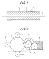
- FIG. 1 is a sectional view of an embodiment of the conductive roller according to the invention.
- FIG. 2 is a partial sectional view of an embodiment of the image forming apparatus according to the invention.
- FIG. 1 is a sectional view of an embodiment of the conductive roller according to the invention.
- the conductive roller 1 shown in the figure comprises a shaft member 2, an elastic layer 3 disposed on an outside of the shaft member 2 in a radial direction and a coating layer 4 disposed on an outside of the elastic layer 3 in a radial direction.
- the conductive roller 1 shown in FIG. 1 comprises only one elastic layer 3, the conductive roller according to the invention may comprise two or more elastic layers.
- the conductive roller 1 shown in FIG. 1 comprises only one coating layer 4, but the conductive roller according to the invention may comprise two or more coating layers.
- the first conductive roller according to the invention is characterized in that at least an innermost layer of the coating layers 4 is composed of an ultraviolet-curing type resin formed by curing an ultraviolet curable raw material mixture comprising a monomer having a heterocycle through ultraviolet irradiation.
- the monomer having the heterocycle can give tenacity and moderate elongation characteristic to the ultraviolet-curing resin. Therefore, even if the strain is caused during the curing of the coating layer, the adhesion property between the elastic layer 3 and the coating layer 4 can be sufficiently assured because the coating layer itself is tenacious and can elongate moderately.
- the second conductive roller according to the invention is characterized in that at least an innermost layer of the coating layers 4 and at least an outermost layer of the elastic layers 3 are composed of an ultraviolet-curing type resin formed by curing an ultraviolet curable raw material mixture comprising at least one polar group-containing monomer selected from the group consisting of a monomer having a heterocycle, a monomer having a hydroxyl group and a monomer having a carboxyl group.
- the innermost layer of the coating layers and the outermost layer of the elastic layers have at least one polar group selected from the group consisting of a heterocycle, a hydroxyl group and a carboxyl group, the polar group in the innermost layer of the coating layers interacts with the polar group in the outermost layer of the elastic layers and thereby the adhesion property between the elastic layer 3 and the coating layer 4 can be sufficiently assured.
- the adhesion property between the elastic layer 3 and the coating layer 4 is particularly good because the coating layer itself is tenacious and can elongate moderately and further the polar group in the innermost layer of the coating layers interacts with the carboxyl group in the outermost layer of the elastic layers.
- the monomer having the heterocycle used in the raw material mixture for the innermost layer in the coating layers of the first and second conductive rollers according to the invention as well as the raw material mixture for the outermost layer in the elastic layers of the second conductive roller according to the invention is required to have a heterocycle in its molecule and is preferable to have a (metha)acryloyloxy group to be cured with ultraviolet rays.
- the heterocycle group are mentioned morpholino group, tetrafurfuryl group, pyrrolidonyl group, caprolactonyl group and so on.
- the monomer having the heterocycle are concretely mentioned acryloyl morpholine, methacryloyl morpholine, tetrahydrofurfuryl (metha)acrylate, N-vinyl pyrrolidone, N-vinyl caprolactam and so on. These monomers having the heterocycle may be used alone or in a combination of two or more.
- the monomer having the hydroxyl group used in the raw material mixture for the innermost layer in the coating layers and the raw material mixture for the outermost layer in the elastic layers of the second conductive roller according to the invention is required to have a hydroxyl group in its molecule and is preferable to have a (metha)acryloyloxy group to be cured with ultraviolet rays.
- the monomer having the hydroxyl group are concretely mentioned 2-hydroxyethyl acrylate, 2-hydroxypropyl acrylate, 2-hydroxybutyl acrylate, pentaerythritol triacrylate, 2-hydroxyethyl methacrylate, 2-hydroxypropyl methacrylate, 2-hydroxybutyl methacrylate, an adduct of phenyl glycidyl ether with acrylic acid, 2-hydroxy-3-phenoxypropyl acrylate and so on.
- These monomers having the hydroxyl group may be used alone or in a combination of two or more.
- the monomer having the carboxyl group used in the raw material mixture for the innermost layer in the coating layers and the raw material mixture for the outermost layer in the elastic layers of the second conductive roller according to the invention is required to have a carboxyl group in its molecule and is preferable to have a (metha)acryloyloxy group to be cured with ultraviolet rays.
- the monomer having the carboxyl group are concretely mentioned ⁇ -(metha)acryloyloxyethyl hydrogen succinate, ⁇ - (metha)acryloyloxypropyl hydrogen succinate, ⁇ -(metha)acryloyloxyethyl hydrogen phthalate, ⁇ -(metha)acryloyloxypropyl hydrogen phthalate, ⁇ -(metha)acryloyloxyethyl hydrogen tetrahydrophthalate, ⁇ -(metha)acryloyloxypropyl hydrogen tetrahydrophthalate, ⁇ -(metha)acryloyloxyethyl hydrogen hexahydrophthalate, ⁇ -(metha)acryloyloxypropyl hydrogen hexahydrophthalate, ⁇ -tris(acryloyloxymethyl)ethyl hydrogen phthalate and so on.
- These monomers having the carboxyl group may be used alone or in a combination of two or more.
- the content of the monomer having the heterocycle in the raw material mixture for the innermost layer of the coating layers is preferably within a range of 20 to 70% by mass.
- the content of the monomer having the heterocycle in the raw material mixture for the innermost layer of the coating layers is less than 20% by mass, it is difficult to give tenacity and moderate elongation characteristic to the innermost layer of the coating layers, while when it exceeds 70% by mass, a hardness of the coating may be increased to cause a crack of the coating during printing.
- the content of the polar group-containing monomer in the raw material mixture for the innermost layer of the coating layers is preferably within a range of 30 to 80% by mass.
- the content of the polar group-containing monomer in the raw material mixture for the innermost layer of the coating layers is less than 30% by mass, it is difficult to give the sufficient adhesion property between the innermost layer of the coating layers and the outermost layer of the elastic layers, while when it exceeds 80% by mass, an elongation of the coating may be deteriorated to cause a breakage.
- the content of the polar group-containing monomer in the raw material mixture for the outermost layer of the elastic layers is preferably within a range of 10 to 80% by mass.
- the content of the polar group-containing monomer in the raw material mixture for the outermost layer of the elastic layers is less than 10% by mass, it is difficult to give the sufficient adhesion property between the innermost layer of the coating layers and the outermost layer of the elastic layers, while when it exceeds 80% by mass, an elongation of the coating may be deteriorated to cause a breakage.
- the ultraviolet curable raw material mixture used for forming the innermost layer of the coating layers is preferable to further comprise an acrylate oligomer, a reactive diluent, a photo-polymerization initiator, a microparticle, a conductive agent and so on.
- the ultraviolet curable raw material mixture used for forming the outermost layer of the elastic layers is preferable to further comprise an acrylate oligomer, a reactive diluent, a photo-polymerization initiator, a conductive agent and so on.
- the coating layer(s) except the innermost layer is not particularly limited and may be similar to or different from the innermost layer in the conductive roller according to the invention.
- the elastic layer(s) except the outermost layer is not particularly limited and may be similar to or different from the outermost layer in the conductive roller according to the invention.
- urethane-based acrylate oligomer As the acrylate oligomer preferably used in the ultraviolet curable raw material mixture are mentioned urethane-based acrylate oligomer, epoxy-based acrylate oligomer, ether-based acrylate oligomer, ester-based acrylate oligomer, polycarbonate-based acrylate oligomer, fluorine-based acrylate oligomer, silicone-based acrylate oligomer and so on.
- the above acrylate oligomer can be synthesized by a reaction of polyethylene glycol, polyoxyproplylene glycol, polytetramethylene ether glycol, bisphenol A-type epoxy resin, phenolic novolac-type epoxy resin, an adduct of polyalcohol and ⁇ -caprolactone or the like and an acrylic acid, or an urethanation of a polyisocyanate compound and an acrylate compound having a hydroxy group.
- the urethane-based acrylate oligomer can be obtained by an urethanation of a polyol, an isocyanate compound and an acrylate compound having a hydroxy group.
- the epoxy-based acrylate oligomer is preferable a reaction product of a compound having a glycidyl group and an acrylic acid, and more prefeable a reaction product of a compound having a cyclic structure such as a benzene ring, a naphthalene ring, a spiro ring, dicyclopentadien, tricyclodecane or the like and a glycidyl group and an acrylic acid.
- the ether-based acrylate oligomer, the ester-based acrylate oligomer and the polycarbonate-based acrylate oligomer can be obtained by a reaction of a polyol (polyether polyol, polyester polyol, and polycarbonate polyol) corresponding to each oligomer and an acrylic acid.
- the ultraviolet curable raw material mixture may comprise an acrylate monomer as a reactive diluent.
- acrylate monomer examples include ethyl acrylate, isobutyl acrylate, n-butyl acrylate, isoamyl acrylate, methoxytriethyleneglycol acrylate, lauryl acrylate, isomyristyl acrylate, stearyl acrylate, myristyl acrylate, palmityl acrylate and so on.
- These acrylate monomers may be used alone or in a combination of two or more.
- the ultraviolet curable raw material mixture preferably comprises a photo-polymerization initiator.
- the photo-polymerization initiator has an action of initiating polymerization of the above-mentioned monomer and acrylate oligomer through ultraviolet irradiation.
- photo-polymerization initiator 4-dimethylaminobenzoic acid, 4-dimethylaminobenzoic ester, 2,2-dimethoxy-2-phenylacetophenone, acetophenone diethyl ketal, alkoxyacetophenone, benzyl dimethyl ketal, benzophenone, benzophenone derivatives such as 3,3-dimethyl-4-methoxy benzophenone, 4,4-dimethoxy benzophenone, 4,4-diamino benzophenone and the like, alkyl benzoylbenzoate, bis(4-dialkylaminophenyl) ketone, benzyl, benzyl derivatives such as benzyl methyl ketal and the like, benzoin, benzoin derivatives such as benzoin isobutyl ether and the like, benzoin isopropyl ether, 2-hydroxy-2-methyl propiophenone, 1-hydroxycyclohexyl phenyl ket
- photo-polymerization initiators may be used alone or in a combination of two or more.
- the amount of the photo-polymerization initiator compounded in the ultraviolet curable raw material mixture is preferably within a range of 0.2 to 5.0 parts by mass based on 100 parts by mass of the total amount of the monomer and the acrylate oligomer.
- the amount of the photo-polymerization initiator compounded is less than 0.2 part by mass, the effect of initiating the ultraviolet curing of the raw material mixture is small, while when it exceeds 5.0 parts by mass, the effect of initiating the ultraviolet curing is saturated and the cost of the raw material mixture becomes high.
- the ultraviolet curable raw material mixture for forming the coating layer may further comprises microparticles.
- On the surface of the conductive roller can be properly formed a micro-unevenness by compounding the microparticle into the raw material mixture for the coating layer.
- the microparticle are preferable microparticles of a rubber, an urethane or a synthetic resin and inorganic microparticles such as carbon microparticles, silica-based microparticles.
- microparticles of silicone rubber, silicone resin, fluorocarbon resin, urethane resin, polyolefin resin, epoxy resin, polystyrene resin, urethane acrylate, melamine resin, phenol resin, (metha)acrylic-based resin and glassy carbon, and silica microparticles are preferable. These microparticles may be used alone or in a combination of two or more. Moreover, the content of the microparticle is preferably within a range of 0.1 to 100 parts by mass based on 100 parts by mass of the total amount of the monomer and the acrylate oligomer.
- a conductive agent in order to give an electric conductivity to the coating layer and the elastic layer
- an ion conductive agent an electron conductive agent and the like.
- ammonium salts such as perchlorate, chlorate, hydrochloride, bromate, iodate, hydroborofluoride, sulfate, ethylsulfate, carboxylate and sulfonate of tetraethyl ammonium, tetrabutyl ammonium, dodecyltrimethyl ammonium, hexadecyltrimethyl ammonium, benzyltrimethyl ammonium and modified-fatty acid dimethylethyl ammonium and the like; perchlorate, chlorate, hydrochloride, bromate, iodate, hydroborofluoride, sulfate, trifluoromethyl sulfate and sulfonate of
- conductive carbons such as Ketjen black, acetylene black and the like; carbon blacks for rubber such as SAF, ISAF, HAF, FEF, GPF, SRF, FT, MT and the like; carbon black for coloring agent treated by oxidation or the like; pyrolyzed carbon black, natural graphite, artificial graphite; metal oxides such as antimony-doped tin oxide, ITO, tin oxide, titanium oxide, zinc oxide and the like; metals such as nickel, copper, silver, germanium and the like; conductive polymers such as polyaniline, polypyrrole, polyacetylene and the like; conductive whiskers such as carbon whisker, graphite whisker, titanium carbide whisker, conductive potassium titanate whisker, conductive barium titanate whisker, conductive titanium oxide whisker, conductive zinc oxide whisker and the like.
- the amount of the conductive agent used can be properly adjusted such that the coating layer and the elastic layer have a desired electric conductivity.
- the coating layer 4 is preferable to have a thickness of 5 ⁇ m to 30 ⁇ m.
- the thickness of the coating layer is less than 5 ⁇ m, the effect developed by disposing the coating layer is small, while when it exceeds 30 ⁇ m, the surface of the conductive roller becomes hard and thereby the flexibility is deteriorated.
- the elastic layer 3 is preferable to have a thickness of 500 ⁇ m to 3 mm.
- the thickness of the elastic layer is not less than 500 ⁇ m, the conductive roller has a sufficient elasticity and the damage to toners is sufficiently small, while when it is not more than 3 mm, ultraviolet rays irradiated can sufficiently reach a deep portion of the elastic layer to surely cure the raw material mixture through ultraviolet irradiation, and the amount of the expensive ultraviolet-curing resin raw material used can be decreased.
- the hardness of the elastic layer is not particularly limited, but is preferably not higher than 90 degrees, more preferably 20 to 80 degrees in an Asker C hardness.
- Asker C hardness of the elastic layer exceeds 90 degrees, the contact area between the conductive roller and the photosensitive drum or the like becomes small and hence the development may not be well conducted, and toners may be damaged and attached to the photosensitive drum or a layer forming blade and hence a faulty image is easily caused.
- the hardness of the elastic layer is excessively low, a friction force between the roller and the photosensitive drum or the layer forming blade becomes large and thereby a faulty image such as jitter or the like may be caused.
- the shaft member of the conductive roller according to the invention is not particularly limited as far as it has a good electrical conductivity, and as the shaft member are mentioned a metal shaft made of a metallic solid body, a hollow cylindrical body made of the metal or high-stiffness resin, a composite formed by disposing a high-stiffness resin on the outer periphery of the metal shaft and the like.
- a conductive agent is added and dispersed into the high-stiffness resin to sufficiently ensure an electrical conductivity.
- the conductive agent to be dispersed into the high-stiffness resin are preferable carbon black powder, graphite powder, carbon fiber, metal powder of aluminum, copper, nickel or the like, powder of a metal oxide such as tin oxide, titanium oxide, zinc oxide or the like, and a powdery conductive agent such as conductive glass powder or the like. These conductive agents may be used alone or in a combination of two or more.
- the amount of the conductive agent compounded is not particularly limited, but is preferably within a range of 5 to 40% by mass, more preferably within a range of 5 to 20% by mass per the whole of the high-stiffness resin.
- polyacetal polyamide 6, polyamide 6 ⁇ 6, polyamide 12, polyamide 4 ⁇ 6, polyamide 6 ⁇ 10, polyamide 6 ⁇ 12, polyamide 11, polyamide MXD6, polybutylene terephthalate, polyphenylene oxide, polyphenylene sulfide, polyether sulfone, polycarbonate, polyimide, polyamide imide, polyether imide, polysulfone, polyether ether ketone, polyethylene terephthalate, polyarylate, liquid crystal polymer, polytetrafluoroethylene, polypropylene, ABS resin, polystyrene, polyethylene, melamine resin, phenol resin, silicone resin and so on.
- polyacetal, polyamide 6 ⁇ 6, polyamide MXD6, polyamide 6 ⁇ 12, polybutylene terephthalate, polyphenylene ether, polyphenylene sulfide and polycarbonate are preferable.
- These high-stiffness resins may be used alone or in a combination of two or more.
- the conductive roller 1 according to the invention can be prepared, for example, by applying the raw material mixture for the elastic layer onto the outer surface of the shaft member 2, irradiating ultraviolet rays to form the elastic layer 3, and then applying the raw material mixture for the coating layer on the outer surface of the resulting elastic layer 3 and irradiating ultraviolet rays to form the coating layer 4. Therefore, the conductive roller according to the invention does not require a long drying line for production and comprises the coating layer having a stable quality.
- a spraying method, a roll-coating method, a dipping method, a die coating method and the like are mentioned a spraying method, a roll-coating method, a dipping method, a die coating method and the like.
- a light source used for the ultraviolet irradiation are mentioned a mercury vapor lamp, a high pressure mercury vapor lamp, a super high pressure mercury vapor lamp, a metal halide lamp, a xenon lamp and the like.
- the conditions for the ultraviolet irradiation are properly selected depending on the components included in the raw material mixtures for the elastic layer and the coating layer, the composition, the amount applied and the like, i.e. the irradiation intensity, integral light quantity and so on may be adjusted properly.
- the above-mentioned conductive roller according to the invention can be used as a developing roller, a charging roller, a toner feed roller, a transfer roller, a paper feed roller, a cleaning roller, a pressure roller for fixing or the like in an image forming apparatus.
- the image forming apparatus according to the invention is characterized by comprising the above-mentioned conductive roller.
- the image forming apparatus according to the invention is not particularly limited as far as it comprises the above-described conductive roller, and can be manufactured according to the known method.
- FIG. 2 is a partial sectional view of an embodiment of the image forming apparatus according to the invention.
- the illustrated image forming apparatus comprises a photosensitive drum 5 carrying an electrostatic latent image, a charging roller 6 positioned near to the photosensitive drum 5 (upside in the figure) for charging the photosensitive drum 5, a toner feed roller 8 for supplying toners 7, a developing roller 9 disposed between the toner feed roller 8 and the photosensitive drum 5, a developing blade 10 disposed near to the developing roller 9 (upside in the figure), a transfer roller 11 positioned near to the photosensitive drum 5 (downside in the figure), and a cleaning roller 12 disposed adjacent to the photosensitive drum 5.
- the image forming apparatus according to the invention may further comprise known members (not shown) usually used for the image forming apparatus.
- the charging roller 6 is contacted with the photosensitive drum 5, and a voltage is applied between the photosensitive drum 5 and the charging roller 6 to charge the photosensitive drum 5 at a constant electric potential, and then an electrostatic latent image is formed on the photosensitive drum 5 by an exposure machine (not shown). Then, the toners 7 are supplied from the toner feed roller 8 to the photosensitive drum 5 through the developing roller 9 by rotating the photosensitive drum 5, the toner feed roller 8 and the developing roller 9 in the direction shown by arrows in the figure.
- the toners 7 on the developing roller 9 are made to be a uniform thin layer by the developing blade 10, while since the developing roller 9 and the photosensitive drum 5 are rotated in contact with each other, the toners 7 are attached from the developing roller 9 to the electrostatic latent image on the photosensitive drum 5 to visualize the latent image.
- the toners 7 attached to the latent image are transferred to a recording medium such as a paper or the like by the transfer roller 11, while the remaining toners 7 on the photosensitive drum 5 after the transferring are removed by the cleaning roller 12.
- the image forming apparatus it is possible to stably form an excellent image by using the above-mentioned conductive roller 1 having high adhesion property between the elastic layer 3 and the coating layer 4 and excellent durability, for example, as at least one of the charging roller 6, the toner feed roller 8, the developing roller 9, the transfer roller 11 and the cleaning roller 12.
- a raw material for an elastic layer comprising 70 parts by mass of UA-334PZ [an urethane acrylate oligomer, manufactured by Shin-Nakamura Chemical Co., Ltd.], 30 parts by mass of LIGHT-ACRYLATE IM-A [isomyristyl acrylate, manufactured by Kyoei-Sha Chemical Co., Ltd.], 1 part by mass of IRGACURE 651 [2,2-dimethoxy-1,2-diphenylethane-1-one, manufactured by Ciba Specialty Chemicals Co., Ltd.] as a photoinitiator, and 2 parts by mass of MP 100 [a complex salt of sodium perchlorate with a polyol, manufactured by Akishima Chemical Industry Co., Ltd.] as an ion conductive agent is applied onto a roller base material (shaft member) made of polybutylene terephthalate (PBT) resin having an outer diameter of 17.0 mm and inserted with a metal shaft having an outer diameter of 6.0 mm at a
- a raw material for a coating layer having a formulation as shown in Tables 1 and 2 is applied onto the surface of the above main roller body through a roll coater and irradiated with UV at an irradiation intensity of 700 mW/cm 2 for 5 seconds to obtain a conductive roller having a UV coating [thickness: 10 ⁇ m] on its surface.
- the adhesion property between the elastic layer and the coating layer of the resulting conductive roller is tested according to a cross cut test of JIS method (JIS K 5600-5-6:1999).
- Example 1 Example 2
- Example 3 Example 4
- Example 5 Raw material for the coating layer Oligomer UF8001 *1 parts by mass 60 60 60 60 60
- the conductive roller provided with the coating layer composed of an ultraviolet-curing type resin formed by curing a raw material mixture comprising a monomer having a heterocycle through ultraviolet irradiation is high in the adhesion property between the elastic layer and the coating layer.
- the conductive roller provided with the elastic layer composed of an ultraviolet-curing type resin formed by curing a raw material mixture comprising a monomer having a carboxyl group through ultraviolet irradiation and the coating layer composed of an ultraviolet-curing type resin formed by curing a raw material mixture comprising a monomer having a heterocycle, a monomer having a hydroxyl group or a monomer having a carboxyl group through ultraviolet irradiation is high in the adhesion property between the elastic layer and the coating layer.
- the adhesion property between the elastic layer and the coating layer is low, when the elastic layer is composed of an ultraviolet-curing type resin formed by curing a raw material mixture not comprising a polar group-containing monomer through ultraviolet irradiation, even if the coating layer is composed of an ultraviolet-curing type resin formed by curing a raw material mixture comprising a polar group-containing monomer through ultraviolet irradiation.
- the adhesion property between the elastic layer and the coating layer is low, when the coating layer is composed of an ultraviolet-curing type resin formed by curing a raw material mixture not comprising a polar group-containing monomer through ultraviolet irradiation, even if the elastic layer is composed of an ultraviolet-curing type resin formed by curing a raw material mixture comprising a polar group-containing monomer through ultraviolet irradiation.
Landscapes
- Physics & Mathematics (AREA)
- General Physics & Mathematics (AREA)
- Engineering & Computer Science (AREA)
- Plasma & Fusion (AREA)
- Rolls And Other Rotary Bodies (AREA)
- Electrophotography Configuration And Component (AREA)
- Electrostatic Charge, Transfer And Separation In Electrography (AREA)
- Dry Development In Electrophotography (AREA)
Applications Claiming Priority (3)
| Application Number | Priority Date | Filing Date | Title |
|---|---|---|---|
| JP2006061048 | 2006-03-07 | ||
| JP2007056119A JP4616297B2 (ja) | 2006-03-07 | 2007-03-06 | 導電性ローラ及びそれを備えた画像形成装置 |
| PCT/JP2007/054470 WO2007102552A1 (fr) | 2006-03-07 | 2007-03-07 | Rouleau electro-conducteur et appareil de formation d'image l'utilisant |
Publications (3)
| Publication Number | Publication Date |
|---|---|
| EP1992997A1 true EP1992997A1 (fr) | 2008-11-19 |
| EP1992997A4 EP1992997A4 (fr) | 2010-04-07 |
| EP1992997B1 EP1992997B1 (fr) | 2013-12-25 |
Family
ID=38474973
Family Applications (1)
| Application Number | Title | Priority Date | Filing Date |
|---|---|---|---|
| EP07737983.2A Ceased EP1992997B1 (fr) | 2006-03-07 | 2007-03-07 | Rouleau electro-conducteur et appareil de formation d'image l'utilisant |
Country Status (5)
| Country | Link |
|---|---|
| US (1) | US20090010690A1 (fr) |
| EP (1) | EP1992997B1 (fr) |
| JP (1) | JP4616297B2 (fr) |
| CN (1) | CN101427188B (fr) |
| WO (1) | WO2007102552A1 (fr) |
Cited By (1)
| Publication number | Priority date | Publication date | Assignee | Title |
|---|---|---|---|---|
| US20090010690A1 (en) * | 2006-03-07 | 2009-01-08 | Bridgestone Corporation | Conductive roller and image forming apparatus comprising the same |
Families Citing this family (8)
| Publication number | Priority date | Publication date | Assignee | Title |
|---|---|---|---|---|
| JPWO2005121906A1 (ja) * | 2004-06-09 | 2008-04-10 | 株式会社ブリヂストン | 現像ローラおよびそれを用いた画像形成装置 |
| JPWO2005121905A1 (ja) * | 2004-06-09 | 2008-04-10 | 株式会社ブリヂストン | 現像ローラおよびそれを用いた画像形成装置 |
| WO2011074610A1 (fr) * | 2009-12-15 | 2011-06-23 | 株式会社ブリヂストン | Rouleau électroconducteur et procédé de fabrication associé |
| US8417163B2 (en) * | 2010-02-12 | 2013-04-09 | Fuji Xerox Co., Ltd. | Resin material, endless belt for image forming apparatus, roller for image forming apparatus, image fixing device, and image forming apparatus |
| US8540900B2 (en) * | 2010-03-25 | 2013-09-24 | Xerox Corporation | Intermediate transfer belts |
| JP5236095B1 (ja) * | 2011-04-12 | 2013-07-17 | キヤノン株式会社 | 膜、膜を有する装置、電子写真感光体、プロセスカートリッジおよび電子写真装置 |
| JP6344999B2 (ja) | 2014-06-30 | 2018-06-20 | 株式会社ブリヂストン | 積層体、導電性ローラ及び積層体の製造方法 |
| CN109416519A (zh) * | 2016-06-20 | 2019-03-01 | 株式会社普利司通 | 导电性辊 |
Family Cites Families (22)
| Publication number | Priority date | Publication date | Assignee | Title |
|---|---|---|---|---|
| US4657835A (en) * | 1984-05-31 | 1987-04-14 | Canon Kabushiki Kaisha | Electrophotographic photosensitive member having an intermediate layer of conductive powder and resin or oligimer |
| JPH0199072A (ja) * | 1987-10-12 | 1989-04-17 | Tokai Rubber Ind Ltd | ロール |
| US5786091A (en) * | 1991-12-02 | 1998-07-28 | Ricoh Company, Ltd. | Charge roller for an image forming apparatus |
| CA2254838C (fr) * | 1997-12-26 | 2007-06-19 | Nitto Kogyo Co., Ltd. | Rouleau de developpement et methode de production |
| EP0928989B1 (fr) * | 1998-01-07 | 2005-10-05 | Canon Kabushiki Kaisha | Elément photosensible électrophotographique, procédé pour sa fabrication, cartouche de traitement et appareil électrophotographique comprenant cet élément |
| US6312792B1 (en) * | 1998-06-10 | 2001-11-06 | Bridgestone Corporation | Electrically conductive member and image-forming apparatus |
| EP1149870A4 (fr) * | 1998-08-20 | 2004-12-08 | Kaneka Corp | Composition pour rouleaux et rouleaux en etant faits |
| JP2000346048A (ja) * | 1999-06-09 | 2000-12-12 | Shin Etsu Polymer Co Ltd | 半導電性シリコーンゴムロール |
| EP1270674A1 (fr) * | 2000-02-07 | 2003-01-02 | Kaneka Corporation | Composition durcissable, rouleau conducteur et tambour conducteur fabriques a partir de celle-ci |
| US6512911B2 (en) * | 2000-07-28 | 2003-01-28 | Bridgestone Corporation | Toner carrier having a particular Z value, a particular creep value, or a particular universal hardness |
| JP2002310136A (ja) | 2001-04-12 | 2002-10-23 | Bridgestone Corp | 発泡体ローラの製造方法及び画像形成装置。 |
| JP2003202748A (ja) * | 2002-01-08 | 2003-07-18 | Canon Chemicals Inc | 現像ローラーの製造方法 |
| CN1275105C (zh) * | 2003-01-07 | 2006-09-13 | 广州市刘氏橡塑制品有限公司 | 一种充电辊及其制造方法 |
| US7175957B2 (en) * | 2003-03-20 | 2007-02-13 | Ricoh Company, Ltd. | Electrophotographic photoconductor, and image forming process, image forming apparatus and process cartridge for an image forming apparatus using the same |
| WO2004106051A1 (fr) * | 2003-05-27 | 2004-12-09 | Circular Technologies | Element d'electrophotographie et son procede de fabrication |
| JP4262044B2 (ja) * | 2003-10-10 | 2009-05-13 | キヤノン株式会社 | 現像ローラ、電子写真プロセスカートリッジ及び電子写真画像形成装置 |
| WO2006001171A1 (fr) | 2004-06-09 | 2006-01-05 | Bridgestone Corporation | Rouleau de developpement, rouleau electrostatique, rouleau conducteur et leur procede de fabrication |
| JP2006023725A (ja) * | 2004-06-10 | 2006-01-26 | Bridgestone Corp | 導電性ローラ及びそれを備えた画像形成装置 |
| US20070197362A1 (en) * | 2006-02-02 | 2007-08-23 | Bridgestone Corporation | Conductive elastic roller and image forming apparatus comprising the same |
| JP4616297B2 (ja) * | 2006-03-07 | 2011-01-19 | 株式会社ブリヂストン | 導電性ローラ及びそれを備えた画像形成装置 |
| EP1847881B1 (fr) * | 2006-04-17 | 2012-03-07 | Ricoh Company, Ltd. | Appareil de formation d'images, procédé de formation d'images et cartouche de procédé |
| US20080146427A1 (en) * | 2006-11-16 | 2008-06-19 | Bridgestone Corporation | Electrical conductive roller and imaging apparatus comprising the same |
-
2007
- 2007-03-06 JP JP2007056119A patent/JP4616297B2/ja active Active
- 2007-03-07 CN CN2007800138791A patent/CN101427188B/zh not_active Expired - Fee Related
- 2007-03-07 US US12/281,690 patent/US20090010690A1/en not_active Abandoned
- 2007-03-07 WO PCT/JP2007/054470 patent/WO2007102552A1/fr not_active Ceased
- 2007-03-07 EP EP07737983.2A patent/EP1992997B1/fr not_active Ceased
Cited By (1)
| Publication number | Priority date | Publication date | Assignee | Title |
|---|---|---|---|---|
| US20090010690A1 (en) * | 2006-03-07 | 2009-01-08 | Bridgestone Corporation | Conductive roller and image forming apparatus comprising the same |
Also Published As
| Publication number | Publication date |
|---|---|
| WO2007102552A1 (fr) | 2007-09-13 |
| EP1992997A4 (fr) | 2010-04-07 |
| JP4616297B2 (ja) | 2011-01-19 |
| CN101427188B (zh) | 2011-08-31 |
| JP2007272218A (ja) | 2007-10-18 |
| EP1992997B1 (fr) | 2013-12-25 |
| US20090010690A1 (en) | 2009-01-08 |
| CN101427188A (zh) | 2009-05-06 |
Similar Documents
| Publication | Publication Date | Title |
|---|---|---|
| EP1992997B1 (fr) | Rouleau electro-conducteur et appareil de formation d'image l'utilisant | |
| JP7258670B2 (ja) | 電子写真用部材、プロセスカートリッジおよび電子写真画像形成装置 | |
| CN106842848B (zh) | 电子照相用构件、显影设备和电子照相设备 | |
| EP3715959B1 (fr) | Élément électrophotographique, cartouche de traitement et appareil électrophotographique de formation d'images | |
| EP2672326B1 (fr) | Rouleau de développement | |
| JP7328114B2 (ja) | 電子写真用部材、プロセスカートリッジおよび電子写真画像形成装置 | |
| WO2011096464A1 (fr) | Bande sans fin conductrice | |
| US20040170449A1 (en) | Developing roller and image forming device | |
| JP4781381B2 (ja) | 電子写真機器用弾性材料および電子写真機器用部材 | |
| JP4996866B2 (ja) | 導電性ローラ及びそれを備えた画像形成装置 | |
| JP4881573B2 (ja) | 導電性ローラ及びそれを備えた画像形成装置 | |
| JP5219411B2 (ja) | 電子写真機器用現像ロール | |
| JP4874051B2 (ja) | 導電性ローラ及びそれを備えた画像形成装置 | |
| JP2006184787A (ja) | 導電性エンドレスベルト、その製造方法およびそれを用いた画像形成装置 | |
| JP4751767B2 (ja) | 導電性ロールおよびその製造方法 | |
| JP4925695B2 (ja) | 導電性ローラ及びそれを備えた画像形成装置 | |
| JP4871797B2 (ja) | 電子写真機器用帯電ロール | |
| JP2005037602A (ja) | 弾性部材及び画像形成装置 | |
| JP4186709B2 (ja) | 現像ローラ、その製造方法及び画像形成装置 | |
| JP5060730B2 (ja) | 導電性ローラ及びそれを備えた画像形成装置 | |
| JP5060764B2 (ja) | 導電性ローラ及びそれを備えた画像形成装置 | |
| JP6979363B2 (ja) | 導電性ローラ及び画像形成装置 | |
| JP2005274650A (ja) | 現像ローラ及びその製造方法、並びに画像形成装置 | |
| WO2019150763A1 (fr) | Rouleau électroconducteur et dispositif de formation d'image | |
| JP2004191562A (ja) | 現像ローラ、その製造方法及び画像形成装置 |
Legal Events
| Date | Code | Title | Description |
|---|---|---|---|
| PUAI | Public reference made under article 153(3) epc to a published international application that has entered the european phase |
Free format text: ORIGINAL CODE: 0009012 |
|
| 17P | Request for examination filed |
Effective date: 20080910 |
|
| AK | Designated contracting states |
Kind code of ref document: A1 Designated state(s): DE FR GB |
|
| DAX | Request for extension of the european patent (deleted) | ||
| RBV | Designated contracting states (corrected) |
Designated state(s): DE FR GB |
|
| A4 | Supplementary search report drawn up and despatched |
Effective date: 20100310 |
|
| 17Q | First examination report despatched |
Effective date: 20100629 |
|
| REG | Reference to a national code |
Ref country code: DE Ref legal event code: R079 Ref document number: 602007034439 Country of ref document: DE Free format text: PREVIOUS MAIN CLASS: G03G0015000000 Ipc: G03G0015020000 |
|
| RIC1 | Information provided on ipc code assigned before grant |
Ipc: G03G 15/02 20060101AFI20130328BHEP Ipc: G03G 15/16 20060101ALI20130328BHEP Ipc: G03G 15/08 20060101ALI20130328BHEP Ipc: F16C 13/00 20060101ALI20130328BHEP |
|
| GRAP | Despatch of communication of intention to grant a patent |
Free format text: ORIGINAL CODE: EPIDOSNIGR1 |
|
| INTG | Intention to grant announced |
Effective date: 20130611 |
|
| RIN1 | Information on inventor provided before grant (corrected) |
Inventor name: KANESUGI, HIROYUKI, BRIDGESTONE CORPORATION Inventor name: AKAMA, SHUYOU, BRIDGESTONE CORPORATION Inventor name: SAKATA, JUNJI, BRIDGESTONE CORPORATION |
|
| GRAS | Grant fee paid |
Free format text: ORIGINAL CODE: EPIDOSNIGR3 |
|
| GRAA | (expected) grant |
Free format text: ORIGINAL CODE: 0009210 |
|
| AK | Designated contracting states |
Kind code of ref document: B1 Designated state(s): DE FR GB |
|
| REG | Reference to a national code |
Ref country code: GB Ref legal event code: FG4D |
|
| REG | Reference to a national code |
Ref country code: DE Ref legal event code: R096 Ref document number: 602007034439 Country of ref document: DE Effective date: 20140213 |
|
| REG | Reference to a national code |
Ref country code: DE Ref legal event code: R097 Ref document number: 602007034439 Country of ref document: DE |
|
| PLBE | No opposition filed within time limit |
Free format text: ORIGINAL CODE: 0009261 |
|
| STAA | Information on the status of an ep patent application or granted ep patent |
Free format text: STATUS: NO OPPOSITION FILED WITHIN TIME LIMIT |
|
| 26N | No opposition filed |
Effective date: 20140926 |
|
| REG | Reference to a national code |
Ref country code: DE Ref legal event code: R097 Ref document number: 602007034439 Country of ref document: DE Effective date: 20140926 |
|
| REG | Reference to a national code |
Ref country code: FR Ref legal event code: PLFP Year of fee payment: 10 |
|
| REG | Reference to a national code |
Ref country code: FR Ref legal event code: PLFP Year of fee payment: 11 |
|
| REG | Reference to a national code |
Ref country code: FR Ref legal event code: PLFP Year of fee payment: 12 |
|
| PGFP | Annual fee paid to national office [announced via postgrant information from national office to epo] |
Ref country code: DE Payment date: 20200320 Year of fee payment: 14 Ref country code: GB Payment date: 20200323 Year of fee payment: 14 |
|
| PGFP | Annual fee paid to national office [announced via postgrant information from national office to epo] |
Ref country code: FR Payment date: 20200319 Year of fee payment: 14 |
|
| REG | Reference to a national code |
Ref country code: DE Ref legal event code: R119 Ref document number: 602007034439 Country of ref document: DE |
|
| GBPC | Gb: european patent ceased through non-payment of renewal fee |
Effective date: 20210307 |
|
| PG25 | Lapsed in a contracting state [announced via postgrant information from national office to epo] |
Ref country code: FR Free format text: LAPSE BECAUSE OF NON-PAYMENT OF DUE FEES Effective date: 20210331 Ref country code: GB Free format text: LAPSE BECAUSE OF NON-PAYMENT OF DUE FEES Effective date: 20210307 Ref country code: DE Free format text: LAPSE BECAUSE OF NON-PAYMENT OF DUE FEES Effective date: 20211001 |