EP1993001A1 - Cartouche de développement - Google Patents
Cartouche de développement Download PDFInfo
- Publication number
- EP1993001A1 EP1993001A1 EP06761578A EP06761578A EP1993001A1 EP 1993001 A1 EP1993001 A1 EP 1993001A1 EP 06761578 A EP06761578 A EP 06761578A EP 06761578 A EP06761578 A EP 06761578A EP 1993001 A1 EP1993001 A1 EP 1993001A1
- Authority
- EP
- European Patent Office
- Prior art keywords
- power
- gear
- power receptor
- developer
- receptor
- Prior art date
- Legal status (The legal status is an assumption and is not a legal conclusion. Google has not performed a legal analysis and makes no representation as to the accuracy of the status listed.)
- Withdrawn
Links
- 238000003756 stirring Methods 0.000 claims abstract description 3
- 238000004519 manufacturing process Methods 0.000 description 2
- 238000009434 installation Methods 0.000 description 1
Images


Classifications
-
- G—PHYSICS
- G03—PHOTOGRAPHY; CINEMATOGRAPHY; ANALOGOUS TECHNIQUES USING WAVES OTHER THAN OPTICAL WAVES; ELECTROGRAPHY; HOLOGRAPHY
- G03G—ELECTROGRAPHY; ELECTROPHOTOGRAPHY; MAGNETOGRAPHY
- G03G15/00—Apparatus for electrographic processes using a charge pattern
- G03G15/06—Apparatus for electrographic processes using a charge pattern for developing
- G03G15/08—Apparatus for electrographic processes using a charge pattern for developing using a solid developer, e.g. powder developer
- G03G15/0896—Arrangements or disposition of the complete developer unit or parts thereof not provided for by groups G03G15/08 - G03G15/0894
-
- G—PHYSICS
- G03—PHOTOGRAPHY; CINEMATOGRAPHY; ANALOGOUS TECHNIQUES USING WAVES OTHER THAN OPTICAL WAVES; ELECTROGRAPHY; HOLOGRAPHY
- G03G—ELECTROGRAPHY; ELECTROPHOTOGRAPHY; MAGNETOGRAPHY
- G03G21/00—Arrangements not provided for by groups G03G13/00 - G03G19/00, e.g. cleaning, elimination of residual charge
- G03G21/16—Mechanical means for facilitating the maintenance of the apparatus, e.g. modular arrangements
- G03G21/1642—Mechanical means for facilitating the maintenance of the apparatus, e.g. modular arrangements for connecting the different parts of the apparatus
- G03G21/1647—Mechanical connection means
-
- G—PHYSICS
- G03—PHOTOGRAPHY; CINEMATOGRAPHY; ANALOGOUS TECHNIQUES USING WAVES OTHER THAN OPTICAL WAVES; ELECTROGRAPHY; HOLOGRAPHY
- G03G—ELECTROGRAPHY; ELECTROPHOTOGRAPHY; MAGNETOGRAPHY
- G03G2221/00—Processes not provided for by group G03G2215/00, e.g. cleaning or residual charge elimination
- G03G2221/16—Mechanical means for facilitating the maintenance of the apparatus, e.g. modular arrangements and complete machine concepts
- G03G2221/1651—Mechanical means for facilitating the maintenance of the apparatus, e.g. modular arrangements and complete machine concepts for connecting the different parts
- G03G2221/1657—Mechanical means for facilitating the maintenance of the apparatus, e.g. modular arrangements and complete machine concepts for connecting the different parts transmitting mechanical drive power
-
- Y—GENERAL TAGGING OF NEW TECHNOLOGICAL DEVELOPMENTS; GENERAL TAGGING OF CROSS-SECTIONAL TECHNOLOGIES SPANNING OVER SEVERAL SECTIONS OF THE IPC; TECHNICAL SUBJECTS COVERED BY FORMER USPC CROSS-REFERENCE ART COLLECTIONS [XRACs] AND DIGESTS
- Y10—TECHNICAL SUBJECTS COVERED BY FORMER USPC
- Y10T—TECHNICAL SUBJECTS COVERED BY FORMER US CLASSIFICATION
- Y10T74/00—Machine element or mechanism
- Y10T74/19—Gearing
- Y10T74/19642—Directly cooperating gears
- Y10T74/19647—Parallel axes or shafts
Definitions
- the present invention relates to a developer cartridge applicable to an electronic photographic developing device.
- electrostatic latent image is formed on a surface of a photosensitive drum serving as an image carrier, and the electrostatic latent image on the photosensitive drum is then developed by a developer carried on a developing drum serving as a developer carrier of a developing device, so as to form a visible image.
- the developer image is transferred onto a material to be transferred, and then is fused for output on a transfer material by a fusing device.
- a type of image processing unit in prior art includes a photosensitive unit and a developing unit detachably combined with the photosensitive unit.
- the photosensitive unit at least includes a photosensitive drum and a transfer roller.
- the developing unit includes a toner cartridge, a stirrer, a supply roller, and a developer roller, and so on.
- the photosensitive unit and the developing unit of the image processing unit have substantially the same developing principle, internal structure, internal means, and relevant positions of the means. Because manufacturers develop different types of machines, in order to prevent the developer cartridge being installed into an incorrect machine by mistake, different developer cartridges have installation limit blocks corresponding to the type of the machine, and a driving position are located at a corresponding position on a side wall. As the developer cartridges have substantially the same basic structure, but must be separated clearly during production, marketing, and using, otherwise, they cannot be used, thus causing unnecessary social costs to some extent.
- the present invention is directed to a developer cartridge applicable to various image forming apparatus.
- the present invention provides a developer cartridge, which includes a toner cartridge, a developer stirring device located in the toner cartridge, a supply roller for supplying a developer to a developer roller, a developer roller for developing an electrostatic latent image on a photoconductor, and a power receptor for driving only one of gear sets of the means to receive a power.
- the power receptor is rotatably fixed at two or more predetermined positions.
- an initial position of the power receptor is a power receiving position
- a power receptor moving device includes a press block, a baffle block, a spring, and a. torsion spring.
- the power receptor moving device is controlled by the press block.
- the press block of the power receptor moving device is pressed downwards, the power receptor is rotated to another power receiving position due to the action of the torsion spring.
- the power receptor and a gear 2 are integrated together, and the gear 2 rotates around a shaft secured on a side plate 6.
- the gear 2 and a gear 3 are fixed oppositely by side plates 6, 7.
- the power receptor 1 receives a power to drive the gear 2 to rotate, the gear 2 is engaged with the gear 3, and the gear 3 is secured to a gear 4, such that the power is transmitted through the gear 4 in sequence, so as to drive rotation means of a developing apparatus to rotate.
- the press block 5 contacts an upper portion 81 of the baffle block 8 through a wedge-shaped surface.
- a right portion 82 of the baffle block 8 is located in a depression 10 formed on the side plate 7, such that the gear 2 and the power receptor 1 are fixed at the initial position, and at the same time, a spring 9 is in a stretched state.
- the press block 5 when it intends to place the power receptor 2 at a second driving position, the press block 5 is pressed downwards in a direction as shown by arrows, such that the press block 5 acts on the upper portion 81 of the baffle block through the wedge-shaped surface to make the spring 9 contracted, and at the same time, the baffle block 8 is moved and reacted in an arrow direction, and the right portion 82 retreats out of the depression 10.
- a torsion spring 11 is located on the side plate 6, and has one end placed in a hole of a side plate 6 and the other end leaned against an inner bottom of a baffling plate 12. When the right portion 82 of the baffle block 8 retreats out of the depression (10), an elastic force of the torsion spring 11 acts on the side plate 6, such that the power receptor (1) is rotated to a second driving position, thus completing the operation.
- an upper surface of the developer cartridge is actually a plane surface.
- the present invention provides a movable driving position by adopting the above technical scheme.
- the driving position is at a fixed position at the gear set side, and the driving position can automatically rotate to another position through a simple operation of a customer, thus being applicable to two or more types of machines having two or more different positions. That is to say, the developer cartridge is made to be universal and applicable to various machines, thus significantly saving social resource to some extent.
- the molds and production lines for producing different developer cartridges are reduced, and for marketing and customers, a series of unnecessary troubles brought by too many types of developer cartridge are avoided.
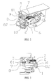
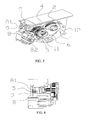
- FIGs. 1 to 6 a developer cartridge according to an embodiment of the present invention is described with reference to FIGs. 1 to 6 .
- a power receptor 1 is at an initial position, which is a power receiving position.
- the power receptor and a gear 2 are integrated together, and the gear 2 rotates around a shaft secured on a side plate 6.
- the gear 2 and a gear 3 are oppositely fixed by side plates 6, 7.
- the power receptor 1 receives a power and drives the gear 2 to rotate, the gear 2 is engaged with the gear 3, and the gear 3 is secured to a gear 4, thus the power is transmitted through the gear 4 in sequence, thereby driving the rotation means of a developing device to rotate.
- a power receptor moving device includes a press block 5, a baffle block 8, and a spring 9.
- the press block 5 contacts an upper portion 81 of the baffle block 8 through a wedge-shaped surface.
- a right portion 82 of the baffle block 8 is located in a depression 10 formed on the side plate 7, such that the gear 2 and the power receptor 1 are fixed at the initial position, and at this time, the spring 9 is in a stretched state
- the press block 5 when it intends to place the power receptor 2 at a second driving position shown in the figures, the press block 5 is pressed downwards in a direction shown by arrows, such that the press block 5 acts on the upper portion 81 of the baffle block through the wedge-shaped surface to make the spring 9 contracted.
- the baffle block 8 is moved and reacted in an arrow direction, and the right portion 82 retreats out of the depression 10.
- a torsion spring 11 is located on the side plate 6, and has one end placed in a hole of the side plate 6 and the other end leaned against an inner bottom of a baffling plate 12.
- an elastic force of the torsion spring 11 acts on the side plate 6, such that the power receptor 1 is rotated to the second driving position, thus completing the operation.
Landscapes
- Physics & Mathematics (AREA)
- General Physics & Mathematics (AREA)
- Electrophotography Configuration And Component (AREA)
- Dry Development In Electrophotography (AREA)
Priority Applications (1)
| Application Number | Priority Date | Filing Date | Title |
|---|---|---|---|
| EP16195886.3A EP3144735A1 (fr) | 2006-02-13 | 2006-07-25 | Cartouche de développement |
Applications Claiming Priority (3)
| Application Number | Priority Date | Filing Date | Title |
|---|---|---|---|
| CN2006100335405A CN101021706B (zh) | 2006-02-13 | 2006-02-13 | 显影剂盒 |
| CN2006100652354A CN101042553B (zh) | 2006-03-21 | 2006-03-21 | 一种显影盒 |
| PCT/CN2006/001848 WO2007093089A1 (fr) | 2006-02-13 | 2006-07-25 | Cartouche de développement |
Related Child Applications (1)
| Application Number | Title | Priority Date | Filing Date |
|---|---|---|---|
| EP16195886.3A Division EP3144735A1 (fr) | 2006-02-13 | 2006-07-25 | Cartouche de développement |
Publications (2)
| Publication Number | Publication Date |
|---|---|
| EP1993001A1 true EP1993001A1 (fr) | 2008-11-19 |
| EP1993001A4 EP1993001A4 (fr) | 2012-04-04 |
Family
ID=38371171
Family Applications (2)
| Application Number | Title | Priority Date | Filing Date |
|---|---|---|---|
| EP16195886.3A Withdrawn EP3144735A1 (fr) | 2006-02-13 | 2006-07-25 | Cartouche de développement |
| EP06761578A Withdrawn EP1993001A4 (fr) | 2006-02-13 | 2006-07-25 | Cartouche de développement |
Family Applications Before (1)
| Application Number | Title | Priority Date | Filing Date |
|---|---|---|---|
| EP16195886.3A Withdrawn EP3144735A1 (fr) | 2006-02-13 | 2006-07-25 | Cartouche de développement |
Country Status (7)
| Country | Link |
|---|---|
| US (1) | US8548353B2 (fr) |
| EP (2) | EP3144735A1 (fr) |
| JP (1) | JP4740345B2 (fr) |
| BR (1) | BRPI0621343A2 (fr) |
| DE (1) | DE202006021282U1 (fr) |
| RU (1) | RU2412456C2 (fr) |
| WO (1) | WO2007093089A1 (fr) |
Cited By (1)
| Publication number | Priority date | Publication date | Assignee | Title |
|---|---|---|---|---|
| CN103238118A (zh) * | 2011-07-27 | 2013-08-07 | 株式会社理光 | 显影剂容器、显影装置、处理单元和成像设备 |
Families Citing this family (2)
| Publication number | Priority date | Publication date | Assignee | Title |
|---|---|---|---|---|
| JP7039226B2 (ja) | 2017-09-21 | 2022-03-22 | キヤノン株式会社 | 現像剤補給容器及び現像剤補給システム |
| JP7047541B2 (ja) * | 2018-03-30 | 2022-04-05 | ブラザー工業株式会社 | 現像カートリッジ |
Family Cites Families (13)
| Publication number | Priority date | Publication date | Assignee | Title |
|---|---|---|---|---|
| JPS6199169A (ja) * | 1984-10-20 | 1986-05-17 | Canon Inc | カラー画像形成装置 |
| JPS6348643A (ja) * | 1986-08-14 | 1988-03-01 | Clarion Co Ltd | 駆動力分岐ギヤ機構 |
| JPS63178262A (ja) * | 1987-01-19 | 1988-07-22 | Canon Inc | 現像装置 |
| US5319418A (en) * | 1989-05-19 | 1994-06-07 | Fujitsu Limited | Image forming apparatus |
| JPH0798523A (ja) * | 1993-09-24 | 1995-04-11 | Canon Inc | プロセスカートリッジ及びプロセスカートリッジへの付加部材 |
| JP3293438B2 (ja) * | 1995-12-28 | 2002-06-17 | 松下電器産業株式会社 | 駆動伝達装置 |
| US6275672B1 (en) * | 1999-11-19 | 2001-08-14 | Nexpress Solutions Llc | Adjustment mechanism for development station elements |
| JP2003015409A (ja) * | 2001-07-05 | 2003-01-17 | Seiko Epson Corp | ロータリー現像装置 |
| CN1328630C (zh) * | 2002-02-05 | 2007-07-25 | 珠海天威飞马打印耗材有限公司 | 一种用于电摄影成像设备的通用粉盒 |
| AU2003211805A1 (en) * | 2002-02-05 | 2003-09-04 | Print-Rite . Unicorn Image Products Co., Ltd. Of Zhuhai | Developer cartridge |
| JP3997817B2 (ja) * | 2002-04-02 | 2007-10-24 | ブラザー工業株式会社 | 現像装置および画像形成装置 |
| JP3542588B2 (ja) * | 2002-09-30 | 2004-07-14 | キヤノン株式会社 | 現像カートリッジ、一端サイドカバーの取付け方法、他端サイドカバーの取付け方法、及び、電子写真画像形成装置 |
| CN2735402Y (zh) * | 2004-09-05 | 2005-10-19 | 珠海纳思达电子科技有限公司 | 一种通用激光打印机碳粉盒 |
-
2006
- 2006-07-25 EP EP16195886.3A patent/EP3144735A1/fr not_active Withdrawn
- 2006-07-25 RU RU2008134731/28A patent/RU2412456C2/ru active
- 2006-07-25 DE DE202006021282.5U patent/DE202006021282U1/de not_active Expired - Lifetime
- 2006-07-25 WO PCT/CN2006/001848 patent/WO2007093089A1/fr not_active Ceased
- 2006-07-25 BR BRPI0621343-0A patent/BRPI0621343A2/pt not_active IP Right Cessation
- 2006-07-25 JP JP2008553601A patent/JP4740345B2/ja active Active
- 2006-07-25 US US12/279,078 patent/US8548353B2/en active Active
- 2006-07-25 EP EP06761578A patent/EP1993001A4/fr not_active Withdrawn
Cited By (1)
| Publication number | Priority date | Publication date | Assignee | Title |
|---|---|---|---|---|
| CN103238118A (zh) * | 2011-07-27 | 2013-08-07 | 株式会社理光 | 显影剂容器、显影装置、处理单元和成像设备 |
Also Published As
| Publication number | Publication date |
|---|---|
| EP3144735A1 (fr) | 2017-03-22 |
| BRPI0621343A2 (pt) | 2011-12-06 |
| WO2007093089A1 (fr) | 2007-08-23 |
| JP2009526249A (ja) | 2009-07-16 |
| US8548353B2 (en) | 2013-10-01 |
| DE202006021282U1 (de) | 2014-08-22 |
| RU2008134731A (ru) | 2010-03-20 |
| RU2412456C2 (ru) | 2011-02-20 |
| JP4740345B2 (ja) | 2011-08-03 |
| US20090220269A1 (en) | 2009-09-03 |
| EP1993001A4 (fr) | 2012-04-04 |
Similar Documents
| Publication | Publication Date | Title |
|---|---|---|
| KR101284973B1 (ko) | 프로세스 카트리지, 전자 사진 화상 형성 장치 및 현상 롤러 | |
| CN103324072B (zh) | 处理盒、显影设备和成像装置 | |
| US8503906B2 (en) | Process cartridge and assembling, disassembling remanufacturing method therefor | |
| US20210109478A1 (en) | Process cartridge and image forming apparatus | |
| CN101923297B (zh) | 图像形成设备 | |
| US20150277367A1 (en) | Process cartridge and image forming apparatus | |
| EP2784598B1 (fr) | Dispositif de transmission de force d'entraînement et appareil de formation d'image comprenant celui-ci | |
| US9285765B2 (en) | Developer supply cartridge with shutter portion for opening and closing a supply opening | |
| KR20060015154A (ko) | 화상형성장치 | |
| US8467698B2 (en) | Image forming apparatus with multiple driving units for driving different components of the image forming apparatus | |
| US9696682B2 (en) | Image forming apparatus and drum unit with conveying unit for conveying toner removed from photosensitive drum | |
| US20140219689A1 (en) | Developer supply cartridge, process cartridge and image forming apparatus | |
| JP6114877B2 (ja) | 回転力伝達機構及び画像形成装置 | |
| KR100729626B1 (ko) | 롤러 이격장치 및 그것을 구비한 화상형성장치 | |
| KR100629497B1 (ko) | 롤러 이격장치 및 그것을 구비한 화상형성장치 | |
| US8548353B2 (en) | Developer cartridge | |
| US7430387B2 (en) | Developing unit and electrophotographic image forming apparatus with the same | |
| US20170293254A1 (en) | Developer cartridge | |
| CN101042553B (zh) | 一种显影盒 | |
| JPH086451A (ja) | 湿式画像形成装置のクリーニング装置 | |
| JP2007047298A (ja) | プロセスカートリッジに用いられる離間部材の位相合わせ組立方法 | |
| JP2001255777A (ja) | 画像形成装置 | |
| HK1134147B (en) | Process cartridge and image forming apparatus | |
| JP2019132992A (ja) | 現像ユニットおよび画像形成装置 |
Legal Events
| Date | Code | Title | Description |
|---|---|---|---|
| PUAI | Public reference made under article 153(3) epc to a published international application that has entered the european phase |
Free format text: ORIGINAL CODE: 0009012 |
|
| 17P | Request for examination filed |
Effective date: 20080813 |
|
| AK | Designated contracting states |
Kind code of ref document: A1 Designated state(s): AT BE BG CH CY CZ DE DK EE ES FI FR GB GR HU IE IS IT LI LT LU LV MC NL PL PT RO SE SI SK TR |
|
| RAP1 | Party data changed (applicant data changed or rights of an application transferred) |
Owner name: ZHUHAI SEINE TECHNOLOGY LIMITED |
|
| A4 | Supplementary search report drawn up and despatched |
Effective date: 20120306 |
|
| RIC1 | Information provided on ipc code assigned before grant |
Ipc: G03G 15/08 20060101AFI20120229BHEP |
|
| DAX | Request for extension of the european patent (deleted) | ||
| 17Q | First examination report despatched |
Effective date: 20150824 |
|
| RAP1 | Party data changed (applicant data changed or rights of an application transferred) |
Owner name: ZHUHAI SEINE TECHNOLOGY LIMITED |
|
| STAA | Information on the status of an ep patent application or granted ep patent |
Free format text: STATUS: EXAMINATION IS IN PROGRESS |
|
| RIN1 | Information on inventor provided before grant (corrected) |
Inventor name: WU, JUN-ZHONG Inventor name: DING, GE-MING |
|
| RAP1 | Party data changed (applicant data changed or rights of an application transferred) |
Owner name: APEX TECHNOLOGY CO., LTD. |
|
| GRAP | Despatch of communication of intention to grant a patent |
Free format text: ORIGINAL CODE: EPIDOSNIGR1 |
|
| STAA | Information on the status of an ep patent application or granted ep patent |
Free format text: STATUS: GRANT OF PATENT IS INTENDED |
|
| INTG | Intention to grant announced |
Effective date: 20170907 |
|
| RAP1 | Party data changed (applicant data changed or rights of an application transferred) |
Owner name: NINESTAR CORPORATION |
|
| STAA | Information on the status of an ep patent application or granted ep patent |
Free format text: STATUS: THE APPLICATION IS DEEMED TO BE WITHDRAWN |
|
| 18D | Application deemed to be withdrawn |
Effective date: 20180118 |